

SERVICE MANUAL
CODE: 00ZAR810//F1E
DIGITAL COPIER
AR-651
MODEL
CONTENTS
1. SPECIFICATIONS . . . . . . . . . . . . . . . . . . . . . . . . . . . . . . . . . . . . . 1-1
2. COMPONENT LAYOUT & FUNCTIONS . . . . . . . . . . . . . . . . . . . . 2-1
3. COPY PROCESS . . . . . . . . . . . . . . . . . . . . . . . . . . . . . . . . . . . . . . 3-1
4. GENERAL OPERATIONS . . . . . . . . . . . . . . . . . . . . . . . . . . . . . . . 4-1
5. CONTROL PANEL . . . . . . . . . . . . . . . . . . . . . . . . . . . . . . . . . . . . . 5-1
6. SCANNING SECTION . . . . . . . . . . . . . . . . . . . . . . . . . . . . . . . . . . 6-1
7. IMAGE PROCESSING . . . . . . . . . . . . . . . . . . . . . . . . . . . . . . . . . . 7-1
8. LASER & OPTICAL UNIT. . . . . . . . . . . . . . . . . . . . . . . . . . . . . . . . 8-1
9. PAPER FEEDING SECTION . . . . . . . . . . . . . . . . . . . . . . . . . . . . . 9-1
10. PROCESS SECTION . . . . . . . . . . . . . . . . . . . . . . . . . . . . . . . . . . 10-1
11. DRUM/CLEANER UNIT . . . . . . . . . . . . . . . . . . . . . . . . . . . . . . . . 11-1
12. DEVELOPER UNIT. . . . . . . . . . . . . . . . . . . . . . . . . . . . . . . . . . . . 12-1
13. TRANSFER/TRANSPORT UNIT . . . . . . . . . . . . . . . . . . . . . . . . . 13-1
14. FUSER UNIT . . . . . . . . . . . . . . . . . . . . . . . . . . . . . . . . . . . . . . . . 14-1
15. EXIT/REVERSING UNIT . . . . . . . . . . . . . . . . . . . . . . . . . . . . . . . 15-1
16. RADF (DOCUMENT FEEDER) . . . . . . . . . . . . . . . . . . . . . . . . . . 16-1
17. POWER SUPPLY UNIT . . . . . . . . . . . . . . . . . . . . . . . . . . . . . . . . 17-1
18. PRINTED WIRING BOARDS . . . . . . . . . . . . . . . . . . . . . . . . . . . . 18-1
19. UNPACKING AND INSTALLATION . . . . . . . . . . . . . . . . . . . . . . . 19-1
AR-810
Parts marked with “ ” are important for maintaining the safety of the set. Be sure to replace these parts with
specified ones for maintaining the safety and performance of the set.
This document has been published to be used
SHARP CORPORATION
for after sales service only.
The contents are subject to change without notice.

GENERAL PRECAUTIONS REGARDING THE INSTALLATION
AND SERVICE FOR THE COPIER AR-651/810
The installation and service should be done by a qualified service technician.
1. Transportation/Installation
• When transporting/installing the copier, move it by the casters while lifting the stoppers.
The copier is quite heavy and weighs approximately 200 kg (441 lb), therefore use caution
when handling it.
• Be sure to use a dedicated line with AC 115V or 120V/20A (220V, 230V, 240V/10A) or more for its
power source.
• The copier must be properly grounded for safety.
Never ground it to a gas pipe or a water pipe.
• Select a suitable place for installation.
Avoid excessive heat, high humidity, dust, vibration, direct sunlight and areas where the temperature may change rapidly such as in direct line with a heating or cooling duct.
• Also provide proper ventilation as the copier emits a slight amount of ozone.
• To insure adequate working space for the copying operation, keep a minimum clearance of
80 cm (32”) on the left, 80 cm (32”) on the right and 10 cm (4”) in the rear.
• The power source must be installed near the copier and should be easily accessible in proper
safety.
Do not use an extension cord to provide power.
2. Service of Machines
• Basically, be sure to turn the main switch off and unplug the power cord during service.
• Be sure not to touch high-temperature sections such as the exposure lamp, the fuser unit, the
damp heater and their periphery.
• Be sure not to touch the high-voltage sections such as the chargers, high-voltage transformer,
exposure lamp control inverter, inverter for the LCD backlight and power supply unit. These components and their PWB's should not be touched even if the power has been turned off since an
electirc charge may remain in their condensers, etc.
• Be sure not to touch rotating/operating sections such as gears, belts, pulleys, fan, etc.
• Be careful when removing the covers since there might be parts with very sharp edges underneath.
• When servicing the machines with the main switch turned on, be sure not to touch live sections
and rotating/operating sections. Avoid exposure to the laser's radiation.
• Use suitable measuring instruments and tools with the proper specifications.
• Avoid exposure to the laser's radiation during servicing.
- Avoid direct exposure to the laser beam.
- Do not insert tools, parts, etc. that are reflective into the path of the laser beam.
- Remove all watches, rings, bracelets, etc. that are reflective.

3. Main Service Parts for Safety
• The breaker's, door switch's, fuse's, thermostat's, thermofuse's, thermistor's, etc. are particularly
important for safety. Be sure to handle/install them properly. Do not allow a short circuit to occur to
maintain the safety rating of the equipment replace these parts with only genuine Sharp parts of
the same type and makers.
4. Cautionary Labels
• During servicing, be sure to check the rating plate and the cautionary labels such as “Unplug the
power cord during service”, “Hot area”, “Laser warning label” etc. to ensure they are legrable a
properly installed to the equipment.
5. Disposition of Consumable Parts, Packing Materials, Used batteries and RAM-ICs
• Regarding the recovery and disposal of the copier, supplies, consumable parts, packing materials,
used batteries and RAM-ICs including litium batteries, it is recommended to follow the relevant
local regulations or rules.
6. When parts are disassembled, reassembly is basically the reverse of disassembly unless
otherwise noted in this manual or other related documents. Be careful not to reassemble
small parts such as screws, washers, pins, E-rings, star washers in the wrong places or in the
wrong order.
7. Basically, the machine should not be operated with any parts removed or disassembled.
8. Precautions Against Static Electricity
• The PC board must be stored in an anti-electrostatic bag and handled carefully using a wristband,
because the ICs on it may become damaged due to static electricity.
Caution: Before using the wristband, pull out the power cord plug of the copier and make
sure that there are no uninsulated charged objects in the vicinity.
Caution : Dispose of used batteries and RAM-ICs including lithium batteries
according with Federal, State and local regulations.
Attention : Se débarrasser de batteries et RAM-ICs usés y compris les batteries en
lithium selon ce manuel.
Vorsicht : Entsorgung des gebrauchten Batterien und RAM-ICs (inklusive
der Lithium-Batterie) nach diesem Handbuch.

CONTENTS
1. SPECIFICATIONS
1. 1. Specifications . . . . . . . . . . . . . . . . . . 1-1
1. 2. Accessories. . . . . . . . . . . . . . . . . . . 1-13
1. 3. Options . . . . . . . . . . . . . . . . . . . . . . 1-13
1. 4. Supplies. . . . . . . . . . . . . . . . . . . . . . 1-14
1. 5. System List . . . . . . . . . . . . . . . . . . . 1-15
2. COMPONENT LAYOUT & FUNCTIONS
2. 1. Sectional View. . . . . . . . . . . . . . . . . . 2-1
2. 2. Electric Parts Layout . . . . . . . . . . . . . 2-5
2. 3. Symbols and Functions of
Various Components. . . . . . . . . . . . 2-16
2. 4. Symbols and Functions of
RADF Various Components . . . . . . 2-24
2. 5. System Block Layout. . . . . . . . . . . . 2-26
2. 6. Disassembly and Replacement
of Covers and PC Boards . . . . . . . . 2-27
3. COPY PROCESS
3. 1. General Description. . . . . . . . . . . . . . 3-1
3. 2. Details of Copy Process . . . . . . . . . . 3-2
3. 3. Comparison of Copy Process
to AR-650/800. . . . . . . . . . . . . . . . . 3-10
4. GENERAL OPERATIONS
4. 1. Overview of Operation. . . . . . . . . . . . 4-1
4. 2. Operation. . . . . . . . . . . . . . . . . . . . . . 4-1
4. 3. Abnormality Detection. . . . . . . . . . . . 4-6
4. 4. Flowchart. . . . . . . . . . . . . . . . . . . . . 4-11
5. CONTROL PANEL
5. 1. Control Panel and Display Panel. . . . 5-1
5. 2. Items Shown on Display Panel . . . . . 5-2
5. 3. Relation between Copier State
and Operator’s Action . . . . . . . . . . . . 5-7
5. 4. Operation. . . . . . . . . . . . . . . . . . . . . . 5-8
5. 5. Disassembly and Replacement. . . . 5-11
6. SCANNING SECTION
6. 1. Function. . . . . . . . . . . . . . . . . . . . . . . 6-1
6. 2. Construction . . . . . . . . . . . . . . . . . . . 6-2
6. 3. Operation. . . . . . . . . . . . . . . . . . . . . . 6-4
6. 4. Control for Exposure Lamp . . . . . . . . 6-7
6. 5. CCD Control . . . . . . . . . . . . . . . . . . 6-10
6. 6. Automatic Original Size
Detection Circuit . . . . . . . . . . . . . . . 6-11
6. 7. Disassembly and Replacement. . . . 6-15
7. IMAGE PROCESSING
7. 1. General Description . . . . . . . . . . . . . 7-1
7. 2. Image Processing Circuit . . . . . . . . . 7-2
7. 3. SLG Board (PWA-F-SLG-340) . . . . . 7-4
7. 4. PLG Board (PWA-F-PLG-340) . . . . . 7-7
7. 5. Scanning Section . . . . . . . . . . . . . . . 7-8
7. 6. Writing Section . . . . . . . . . . . . . . . . . 7-8
8. LASER & OPTICAL UNIT
8. 1. General Description . . . . . . . . . . . . . 8-1
8. 2. Structure . . . . . . . . . . . . . . . . . . . . . . 8-3
8. 3. Laser Diode . . . . . . . . . . . . . . . . . . . 8-7
8. 4. Disassembly and Replacement . . . . 8-8
9. PAPER FEEDING SECTION
9. 1. General Description . . . . . . . . . . . . . 9-1
9. 2. Functions . . . . . . . . . . . . . . . . . . . . . 9-1
9. 3. Operation . . . . . . . . . . . . . . . . . . . . . 9-4
9. 4. Drive Circuit for Tray-up Motor . . . . 9-10
9. 5. Disassembly and Replacement . . . 9-11
10. PROCESS SECTION
10. 1. Construction . . . . . . . . . . . . . . . . . . 10-1
10. 2. Functions . . . . . . . . . . . . . . . . . . . . 10-2
10. 3. Charger Wire Cleaner
Operational Circuit . . . . . . . . . . . . . 10-3
10. 4. High-voltage Transformer
Output Control Circuit . . . . . . . . . . . 10-4
10. 5. Surface Potential Sensor . . . . . . . . 10-6
10. 6. Disassembly and Replacement . . . 10-8
11. DRUM/CLEANER UNIT
11. 1. Construction . . . . . . . . . . . . . . . . . . 11-1
11. 2. Functions . . . . . . . . . . . . . . . . . . . . 11-2
11. 3. Drum Temperature Detection
Circuit . . . . . . . . . . . . . . . . . . . . . . . 11-2
11. 4. Image Quality Control . . . . . . . . . . . 11-3
11. 5. Disassembly and Replacement . . . 11-6
12. DEVELOPER UNIT
12. 1. Construction . . . . . . . . . . . . . . . . . . 12-1
12. 2. Functions . . . . . . . . . . . . . . . . . . . . 12-2
12. 3. Developer Unit Drive. . . . . . . . . . . . 12-4
12. 4. Motor Drive Circuit . . . . . . . . . . . . . 12-6
12. 5. Auto-toner Sensor Circuit . . . . . . . . 12-9
12. 6. Disassembly and Replacement . . 12-12
13. TRANSFER/TRANSPORT UNIT
13. 1. General Description . . . . . . . . . . . . 13-1
13. 2. Operation . . . . . . . . . . . . . . . . . . . . 13-1
13. 3. Functions . . . . . . . . . . . . . . . . . . . . 13-2
13. 4. Disassembly and Replacement . . . 13-4
I

14. FUSER UNIT
14. 1. General Description. . . . . . . . . . . . . 14-1
14. 2. Operation. . . . . . . . . . . . . . . . . . . . . 14-1
14. 3. Functions. . . . . . . . . . . . . . . . . . . . . 14-2
14. 4. Heater Control Circuit . . . . . . . . . . . 14-4
14. 5. Fuser Motor Drive . . . . . . . . . . . . . 14-11
14. 6. Disassembly and Replacement. . . 14-13
15. EXIT/REVERSING UNIT
15. 1. General Description. . . . . . . . . . . . . 15-1
15. 2. Operation. . . . . . . . . . . . . . . . . . . . . 15-1
15. 3. Disassembly and Replacement. . . . 15-6
16. RADF (DOCUMENT FEEDER)
16. 1. General Description. . . . . . . . . . . . . 16-1
16. 2. Construction . . . . . . . . . . . . . . . . . . 16-2
16. 3. Drive System. . . . . . . . . . . . . . . . . . 16-3
16. 4. Signal Block Diagram . . . . . . . . . . . 16-6
16. 5. Operations. . . . . . . . . . . . . . . . . . . . 16-7
16. 6. Jams . . . . . . . . . . . . . . . . . . . . . . . 16-32
16. 7. Errors. . . . . . . . . . . . . . . . . . . . . . . 16-37
16. 8. Original Size Detection . . . . . . . . . 16-38
16. 9. Flow Chart. . . . . . . . . . . . . . . . . . . 16-41
16. 10. Timing Chart . . . . . . . . . . . . . . . . . 16-57
16. 11. Circuits . . . . . . . . . . . . . . . . . . . . . 16-62
16. 12. Input/Output Signals . . . . . . . . . . . 16-68
16. 13. Disassembly and Replacement. . . 16-73
17. POWER SUPPLY UNIT
17. 1. Construction . . . . . . . . . . . . . . . . . . 17-1
17. 2. Operation of DC Output Circuits . . . 17-1
17. 3. Output Channel. . . . . . . . . . . . . . . . 17-2
17. 4. Fuse . . . . . . . . . . . . . . . . . . . . . . . . 17-5
17. 5. Configuration of Power Supply
Unit . . . . . . . . . . . . . . . . . . . . . . . . . 17-7
17. 6. Power Supply Sequence. . . . . . . . . 17-8
18. PRINTED WIRING BOARDS . . . . . . . . . . . 18-1
19. UNPACKING AND INSTALLATION . . . . . . 19-1
II
1. SPECIFICATIONS
1.1. Specifications
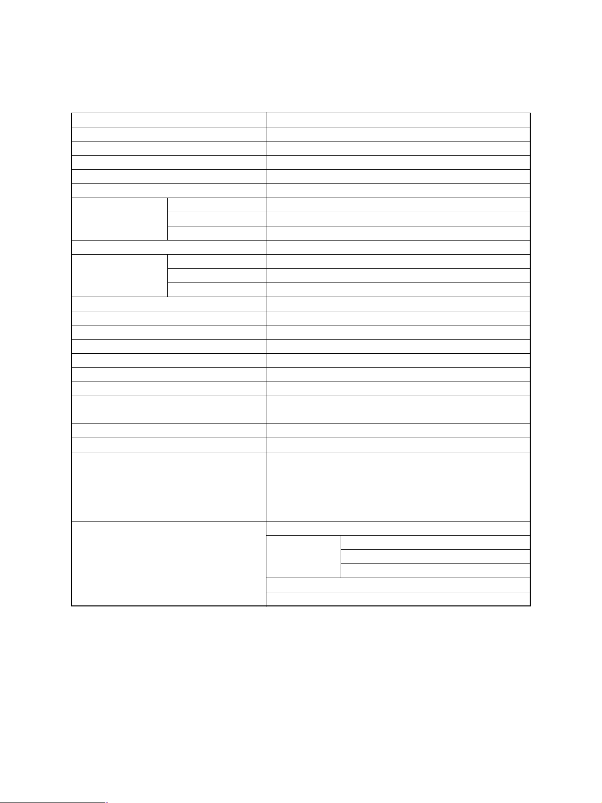
1.1.1. System
Copy system Indirect electronic photo system (Dry type)
Body type Console type
Original table type Fixed type (Left rear reference)
Original cover RADF standard provision
Frame structure Fixed frame type
Photoconductor OPC drum (φ100)
Original scan system Scan sensor CCD line sensor (7500 pixel)
Scan resolution 600 x 600 dpi
Scan light source Xenon lamp
Scan data output system 1 scan multi copy system
Exposure system Exposure light source Semiconductor laser
Exposure resolution 600 dpi
Scan system Use of Polygon mirror
Developing system 2-component magnetic brush development system
Discharging system Photo discharge by red LED
Charging system Negative corona system (Scorotron)
Transfer system Transfer belt system
Separation system Transfer belt system
Transfer belt cleaning system Fur brush system + blade system
Drum cleaning system Blade system + Fur brush system
Toner supply system Front side toner cartridge supply
Note: Toner supply inhibited during printing
Toner concentration adjustment system Magnetic auto toner system
Toner recycle Yes
Toner empty detection system Electric detection system (Auto toner sensor)
Note: When toner empty is detected, the toner supply symbol
flashes and the message is displayed.
Copying is inhibited until the toner concentration is
recovered.
Fusing system Heat roller system
Induced heating
system
Roller diameter (Upper) φ60
Roller diameter (Lower) φ60
700 to 1450 W (100V)
6000 to 1500 W (115V)
700 to 1500 W (230V)
AR-651/810 SPECIFICATIONS 1 - 1
1.1.2. Basic specifications
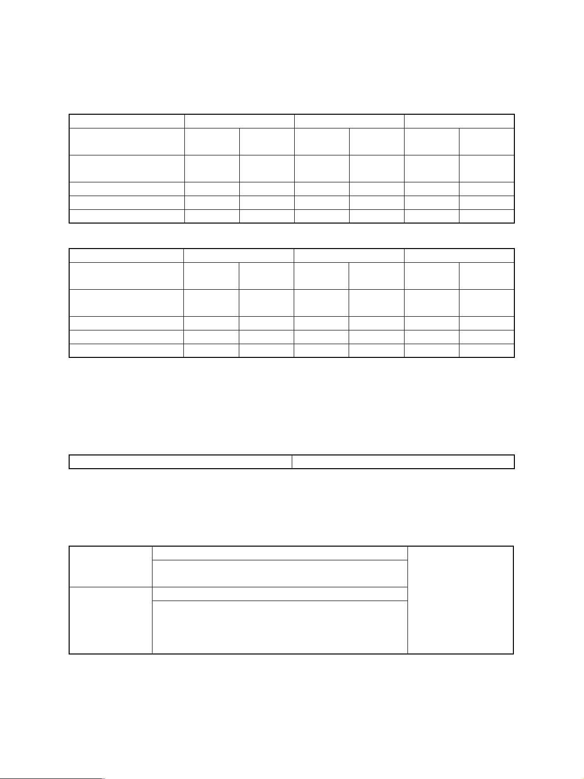
A. Copy speed
(1) Continuous copy
AR-651 (cpm)
Paper feed system Cassette LCF (Note 3) Manual feed (Note 4)
Paper size Face up
exit
A4, B5, A5-R, LT, ST-R
A4-R, B5-R, LT-R 50 48 — — 42 42
B4, FOLIO, LG, COMP 43 40 — — 37 37
A3, LD 37 34 — — 33 33
AR-810 (cpm)
Paper feed means PFP LCF (Note 3) Manual feed (Note 4)
Paper size Face up
A4, B5, A5-R, LT, ST-R
A4-R, B5-R, LT-R 61 56 — — 44 44
B4, FOLIO, LG, COMP 52 45 — — 39 39
A3, LD 43 37 — — 34 34
Note 1: Specification for manual set document, single copy, non-sort continuous copy
Note 2: State not entering the toner supply mode
Note 3: LCF is a tandem LCF (standard provision).
Note 4: Copy speed for manual feed is a speed with the size specified. If the size is not specified, the copy speed
is same as that of A3/LD.
65 65
exit
81 81
Face down
exit
Face down
exit
Face up
exit
65
(A4, LT)
Face up
exit
81
(A4, LT)
Face down
exit
65
(A4, LT)
Face down
exit
81
(A4, LT)
Face up
exit
48 48
Face up
exit
50 50
Face down
exit
Face down
exit
(2) First copy
First copy time 3.2 sec or less
Note 1: The above specification is for manual set document, normal ratio, A4/LT size, 1st stage cassette paper
feed, and face-up exit.
Note 2: When APS is not used.
B. Warm-up time
Normal About 160sec (160sec + 20% or less) Evaluation conditions
Note 1: State not entering the toner supply mode
Note 2: When there is no preceding entry
Pre-heating About 45sec
Note 1: When the heater is at 155°C in preheating (AR-651)
When the heater is at 70°C in preheating (AR-810)
Note 2: State not entering the toner supply mode
Note 3: When there is no preceding entry
AR-651/810 SPECIFICATIONS 1 - 2
1. Room temperature
20°C or above
2. Rated power
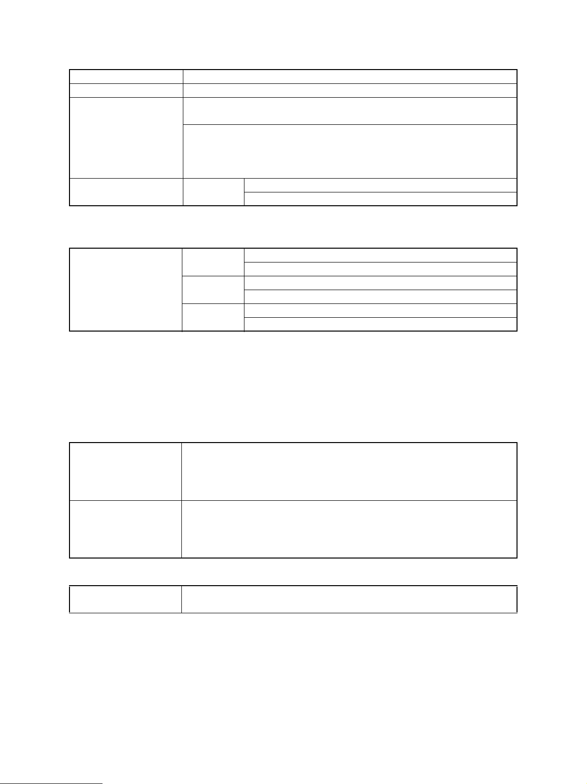
C. Original
Max. size A3 or LD
Kind Sheet, cubic material, book
Original size detection Glass surface: Yes
Note 1: Fixed detection system with the RADF open
RADF: Yes
Note 1: Document width and length are detected in RADF paper feed.
Note 2: Only the first paper is detected except when mixed sizes of sheets are
loaded.
Allowable original size for
auto detection
Fixed size AB series: A3, A4, A4-R, A5-R, B4, B5, B5-R
LT series: LD, LG, LT, LT-R, ST-R
D. Paper
(1) Size
Fixed size Cassette AB series: A3, A4, A4-R, A5-R, B4, B5, B5-R, FOLIO
LT series: LD, LG, LT, LT-R, ST-R, COM
Tandem LCF AB series: A4
LT series: LT
Manual feed AB series: A3, A4, A4-R, A5-R, B4, B5, B5-R, FOLIO
LT series: LD, LG, LT, LT-R, ST-R, COM
Note 1: Postcards can be used. (Reverse copy and duplex copy are inhibited.)
Note 2: Name cards cannot be used.
Note 3: Same surface copy cannot be used.
Note 4: Envelopes cannot be used.
Note 5: Fixed-size paper width is detected with the manual feed tray guide width.
Note 6: Manual feed of mixed-size sheets cannot be made.
(2) Kind
Cassette
Manual feed
(3) Max. weight
Cassette/Manual feed 64 to 209 g/m²
Note 1: 80 to 209 g/m² or less available in the Heavy paper mode.
• PPC paper
Note 1: Tracing paper, OHP films, label paper, postcards, and other special paper
cannot be used.
Note 2: Tab paper can be used only in the second stage cassette.
• PPC paper
• Tracing paper: Out of warranty for reliability
• OHP film: Out of warranty for reliability
• Tab paper: Out of warranty for reliability
17 lbs to 110 lbs-index
AR-651/810 SPECIFICATIONS 1 - 3
E. Paper feed
Paper feed means Cassette, 2 steps
Tandem LCF
Manual feed
Capacity Cassette: 500 sheets (Loading height: 55mm or less)
Tandem LCF: 1250 x 2 sheets (Loading height: 137mm or
less)
Manual feed: 100 sheets (Loading height: 11mm or less)
Manual feed start START key start
Priority paper feed means Yes
Note 1: Priority can be switched to the other paper feed
means by date input in the adjustment mode.
Manual feed size
specification
Paper size change The paper guide in the cassette is shifted to the fixed size
Can be specified by pressing the paper size key after loading
paper.
Note 1: Size specification allows binding margin, duplex edge
erase, and continuous paper copy.
position, and the paper size is changed by the setup code or
the setup of the special menu.
F. Continuous copy
Tandem LCF
Number of copies 1 to 9999 sheets (Max. number of copies), in increment of 1
Input system Input by 10 key
Counting system Reduction system
Note 1: "1" is displayed in auto clear or during warm-up.
Note 2: Count-down display on the print status display for every print job
Note 3: For a cop job, the status is also displayed on the copy display.
G. Density adjustment
Automatic density
adjustment
Manual density
adjustment
Priority mode Automatic density adjustment
Yes
11-step adjustment (Operated by keys on the control panel
LCD)
Factory setup: Auto
Note 1: Selection of automatic/manual is available by data
input in the adjustment mode.
H. Picture quality mode
Image process mode Standard mode/Photo mode/Text mode
Priority mode Standard mode
Note 1: Selectable by data input in the adjustment mode.
I. Magnification ratio
(1) Reduction, enlargement
Reduction, enlargement Automatic setup by selection of the document size and the paper size
Note 1: Any fixed size (including different series) can be set to Japan A5, OTHER.
AR-651/810 SPECIFICATIONS 1 - 4
(2) Selected magnification ratio
a. AB series
Paper
Document
A3 B4 FOLIO A4 B5 A5
A3 100 86 71 71 61 50
B4 115 100 82 82 71 57
FOLIO 127 110 100 90 78 63
A4 141 122 100 100 86 71
B5 163 141 115 115 100 82
A5 200 173 141 141 122 100
b. LT Series
Paper
Document
LD COMP LG LT ST
LD 100 82 78 65 50
COMP 108 100 84 78 54
LG 121 100 100 78 60
LT 129 119 100 100 65
ST 200 165 154 129 100
Note: Figures indicate the selected magnification ratios (%).
(3) Others
Zoom 25 to 400%, in increment of 1%
25 to 200%, in increment of 1% (when the RADF is used)
Copy range display No
Note 1: The center position is displayed in continuous
paper copy and book copy.
Automatic paper select(APS)/
Yes Priority on APS
Automatic magnification ratio
select (AMS)
when shipping
J. Counter display
Total counter Mechanical, 7 digits
Displayed on the control panel.
A3/LD double count mode Yes (Electronic counter) Factory setup: ON
PM counter Yes (Electronic counter) Factory setup: 460K, 500K
Resettable counter No
Document counter Yes (Electronic counter) Factory setup
Europe: Yes
Others: No
JOB counter Copy counter
Print counter
Copy scan counter
File/network scan counter
AR-651/810 SPECIFICATIONS 1 - 5
K. Charger wire cleaning
Charger wire cleaning Automatic cleaning system
Note: The charger wire is cleaned.
L. Special functions
Interruption Yes
Pre-heating Yes Key input can be
Note 1: Automatic pre-heat function can be set in the
adjustment mode.
Note 2: Time can be set in the adjustment mode.
(Setup: 15, 20, 30, 45, 60 min)
Note 3: The fusing unit temperature in pre-heating can be
changed in the adjustment mode.
Sleep Yes (when the controller is connected) Excluding the options and
Note: The power consumption in the sleep mode is max.
20W.
Auto off Yes (When the controller is not connected)
Note 1: Time up to off can be set in the adjustment mode or
on the adjustment menu. (Max. 240 min.)
Note 2: Use/Non-use can be selected by setup on the
adjustment mode.
Note 3: Selection of user setup allow/inhibit on time setup
can be set.
Auto clear Yes
Note: Setup can be changed in the adjustment mode or on
the adjustment menu. (15 to 150sec (in increment of
15 sec))
Self diag Yes
Error code history Yes
Department
management (pass
code function)
Dew prevention Yes (Option depending on the destination)
Message Yes
All clear Yes
Mode memory Yes (4 modes) Inhibited in interruption
Cover mode Yes (following 4 modes)
Yes (The number of copies and the number of prints are
managed for each department.)
Note 1: Entry of the pass code in 5 digits is required when
supplying the power or in auto clear for copying.
Note 2: Common use with the key counter is inhibited.
Note 3: Max. 150 kinds can be set.
Note 1: Graphic LCD, back-light provided
(1) White cover mode
(2) Copy cover mode
(3) White cover/white back cover mode
(4) Copy cover/white back cover mode
accepted during warm-up
or ready state.
Factory setup (Note 2):
15 min
the dump heater.
Factory setup (Note 1):
90 min
Factory setup (Note 2):
Yes
Factory setup (Note 3)
Japan, North America,
Australia: Allow
Europe: Inhibit
Factory setup: 45sec
Factory setup: OFF
Entry of OOOO is
rejected. (Note 1)
copy
AR-651/810 SPECIFICATIONS 1 - 6
Sheet insertion mode Yes (following 2 modes)
(1) White sheet insertion mode
(2) Copy paper insertion mode
Weekly timer Yes
Pre-heat start Yes
Pre-heat copy Yes
Max. 6 jobs.
Note 1: The next copy job mode setup can be made when
document scan is completed. When the START key
is pressed, preceding entry of document is started.
Note 2: In the 6th job, the machine is in the scan reservation
state. After completion of copy 1 job, scan is
automatically started.
Automatic duplex
Yes Factory setup: OFF
automatic selection
Time display Yes
Copy riser support No
Automatic sort Yes Factory setup: ON
Automatic cassette
Yes
selection
Network printer Network printer board can be connected. (Option)
DSS No
Language selection Yes (Japanese, English, German, French, Spanish, Italian:
Factory setup)
Note: Language data depends on the HDD.
FROM update Yes (following 2 methods)
Serviceman support
(1) Downloading from PC
(2) Downloading from a jig PC board.
Adjustment code
Yes (05, 08 code) Serviceman support
output
Mixed-size document
Yes (when the RADF is installed)
mode
Heavy paper mode Yes
Note 1: One of the following two modes must be selected
according to the kind of Heavy paper.
• Heavy paper mode 1: For paper of 80 g/m² to 163
g/m²
• Heavy paper mode 2: For paper of 163 g/m² - 209
g/m²
Note 2: The copy speed standard for using Heavy paper is
as shown below:
• Cassette, LCF (Tandem) paper feed, A4/LT size
Paper used for evaluation
North America: Wausau
AR-651 AR-810
Normal paper 65 81
Heavy paper mode 1 65 81
Exact/Index
Europe: Noisydra Color
Copy
Heavy paper mode 2 65 65
Note 3: The duplex function is available.
AR-651/810 SPECIFICATIONS 1 - 7
M. Edit functions
Continuous paper copy Yes
Edge erase Yes
Note: The edge erase priority mode
can be selected by the
adjustment mode.
Binding margin (Image shift) Yes
Trimming, masking Yes
2 in 1 Yes
4 in 1 Yes Normal position for document set
Factory setup: No priority
N. Tab paper
Paper feed means Supported only for manual paper feed and the second stage cassette.
Paper feed direction The tab side must be on the rear side when feeding.
Kind of tab paper A4/LT size
Tab width
Print on the tab
section
Duplex print No
Staple Yes
Punch Yes
Insert Yes
• Manual paper feed: 10 to 20 mm
• Cassette 2: 12 to 17mm
Note 1: Initial value of tab width: 13mm
Yes
Note 1: The overall input image is shifted toward the tab side (rear edge).
Note 2: The copy speed is reduced similarly to the heavy paper mode.
Note 1: Selection inhibited between Single ⇒ Duplex and Duplex ⇒ Duplex
Note 2: In duplex print with tab paper inserted, single print is made only in the tab paper.
Note: There is a limitation on the number of stapled sheets according to the heavy
paper specifications.
Note: When tab paper is inserted, tab paper is not punched. However, punching on tab
paper can be set in the setup mode.
O. Digital edit function
Independent zoom Yes
Mirror image Yes
Black-white reversion Yes
Electronic sort Yes
Magazine sort Yes
Page numbering Yes
Rotation copy Yes
Image overlay Yes
Document storage Yes
Date/time writing Yes
Image direction Yes
AR-651/810 SPECIFICATIONS 1 - 8
P. Operation panel
Operation keys Hard key
Note 1: The number of keys is 19 as follows:
ENERGY SAVER
INTERRUPT
CLEAR ALL (CA)
CLEAR
STOP
START
PRINTER/NETWORK
COPY
0 to 9 (10 keys)
JOB STATUS
HELP
Status display Displayed with the message display and LED
Note 1: There are following 9 LEDs.
ENERGY SAVER
TIMER
INTERRUPT
CLEAR ALL
PRINTER/NETWORK
DATA
ERROR
COPY
JOB STASUS
Message display Graphic LCD with touch panel (with back-light)
Note 1: Detail of LCD
Number of display dots: 320 x 240 (1/4 VGA)
Display area: 115.17mm x 86.37mm
Display mode: Blue mode
Print status key Yes
The display when the print status key is pressed is composed of the job list, the print status,
and the cassette tab.
• Job list: The print jobs are listed. The job sequence can be changed and any job can be
deleted.
• Print status: Indicates which paper feed stage is used. In case of paper empty, the paper
feed stage blinks.
• Cassette: The cassette size and the attribute (cover paper, sheet, special) can be set.
Q. Environmental conditions
Normal use 10 to 30°C, 20 to 85% RH, without dew Recommended paper
immediately after
unpacking must be used.
Special use (1) –5 to 10°C, 20 to 85% RH, without dew
(2) 30 to 35°C, 20 to 85% RH, without dew
Transit and storage with
consumable parts packed together
Transit and storage with
consumable parts packed together
Transit and storage of consumable
parts
–10 to 35°C, 85% RH or less, without dew
–40 to 50°C, 85% RH or less, without dew
–10 to 35°C, 85% RH or less, without dew
AR-651/810 SPECIFICATIONS 1 - 9
R. Noises
When ready 45dB (A) or less
When continuous copying 65dB (A) or less
S. Complying standards
Safety standards 1) Electric appliances safety regulation
2) S mark
3) UL
4) CSA (C-UL)
5) CDRH
6) TUV
7) CE mark
Interruption wave
standards
1) VCCI
2) FCC (IC)
3) CE mark
4) C-TICK (Australia)
5) Radio wave regulations
6) Domestic harmonic wave
T. Power source
Power voltage, frequency 100V-50/60Hz, 115V-50/60Hz, 220 to 240V-50/60Hz
Power consumption 2.0 kW or less
Note: Including options.
Power cord 2m
Note: Detachable for the 200 series.
U. External view
External dimensions (1) Machine: W698 x D777 x H1213 mm
Note 1: Excluding the manual paper feed tray and the paper exit tray.
(2) Machine + finisher: W1416 x D777 x H1213 mm
Note 1: Excluding the manual paper feed tray.
Weight Machine only: 214 kg (including developer and the OPC drum)
Occupying area (1) Machine only: W1401 x D777 mm
Note: Including the manual feed tray and the paper exit tray.
(2) Machine + finisher: W1742 x D777 mm
Note: Including the manual feed tray and the finisher tray.
V. Packing
External dimensions W764 x D867 x H1305 mm (including the pallet)
Weight 240 kg
Items packed together Operation Manual
OPC drum
Drum cover
Operation Manual pocket
Spacer for the document tray
Rear edge guide for tab paper
Maintenance management table (CCASZ0067FC02)
Delivery and installation report (TCADZ1510FCZZ) (Australia)
MSDS card (TCADZ) (North America, Europe)
Warranty paper for Australia (TGANE1001QCZB) (Australia)
cover-screws, 3 pcs.
AR-651/810 SPECIFICATIONS 1 - 10
W. Maintenance
(1) Periodic inspection
AR-651 AR810
Execution interval 460,000 sheets 500,000 sheets
X. Automatic document feeder
Automatic document feeder Standard provision
(1)Functions
Functions Automatic separation and feed of loaded documents
a) Automatic magnification ratio/paper selection
b) Duplex documents supported
c) SADF/ADF
Allowed documents Fixed size AB series: A3, A4, A4-R, A5-R, B4, B5, B5-R
LT series: LD, LG, LT, LT-R, ST-R
Kind: Quality paper
Max. weight Single copy documents: 50 g/m² to 127 g/m² (13 to 34 Lbs)
Duplex documents: 50 g/m² to 104 g/m² (13 to 28 Lbs)
Document capacity 100 sheets or loading height 16 mm or less
Note: All size 80 g/m² or 20lbs paper
Process speed Corresponding to 65 sheets/min
Note 1: A4/LT size, single → Single mode, normal ratio
Document process method Loading: The last document at the bottom, face up
Paper feed method: From the top, fed one by one to the copy section.
Paper exit method: From the top, face down, accumulated sequentially
Document position Center reference
Power source Supplied from the machine
Use frequency Print quantity: RADF = 5 : 1 (Single document : Duplex document = 20 : 1)
Y. Automatic duplex unit
Automatic duplex unit Standard provision
Kind Stackless, switchback duplex unit
Allowable paper Fixed size AB series: A3, A4, A4-R, A5-R, B4, B5, B5-R, FOLIO
LT series: LD, LG, LT, LT-R, ST-R, COM
Kind PPC paper
Paper weight Weight: 64 to 209 g/m² (17 lbs to 110 lbs-index)
Curl level 5 mm or less (Paper feed section)
Transport reference Center reference
AR-651/810 SPECIFICATIONS 1 - 11
Z. Tandem LCF
Standard provision
Kind Single paper feed (Right), single shift (Left) type large
capacity paper feed unit
Paper supply system Front loading type No separation of right
and left (Overall pull-out)
Max. loading capacity Loading height: 137mm or less x 2 stages
(1250 x 2 sheets, paper thickness 0.106mm, 80 g/m² /
20 lbs paper)
Allowable paper size AB series: A4
LT series: LT
Paper kind PPC paper
(OHP films, gum labels, and special paper cannot be
used.)
Paper weight 64 to 209 g/m²
17 lbs-bond to 110 lbs-index
Transport reference Center reference
Curl level 5 mm or less
1.1.3. Image, image specifications
A. Image quality
Image density 1.0 or above Original density: 1.0
Background copy 3.0% or less Difference in reflection ratio with
non-transferred paper
Resolution Normal ratio 100%: Vertical 4.0 mm or above/
Horizontal 3.6 mm or above
Enlargement 200%: Vertical 4.5mm or above/
Horizontal 4.0 mm or above
Reduction 50%: Vertical 2.0 mm or above/
Horizontal 1.7mm or above
Gradation Standard: 5 steps or more Evaluated in the gradation
Text: 4 steps or more
Photo: 6 steps or more
Distortion ±1.0%
Magnification ratio error Normal ratio: ±1.0%
Enlargement 200% / Reduction 50%: ±1.5%
Lead edge position shift Machine 0±2 mm
System 0±4.0 mm
Horizontal shift Machine 0±3.0 mm
System 0±4.0 mm
Slant Machine 1.0 mm or less
System 3.0 mm or less/200 mm
evaluation step. Measured with
the background as 1 step.
Machine: Fixed document,
single-side, normal ratio
Machine: Fixed document,
single-side, normal ratio, sort
mode
Machine: Fixed document,
single-side, normal ratio
AR-651/810 SPECIFICATIONS 1 - 12
1.2. Accessories
Operation manual
Drum
Drum cover
Operation Manual pocket
Spacer for original tray
Rear edge guide for tab paper
Maintenance management table (CCASZ0067FC02)
Delivery and installation report (TCADZ1510FCZZ) (Australia)
MSDS card (TCADZ) (North America, Europe)
Warranty paper for Australia (TGANE1001QCZB) (Australia)
cover-screws, 3 pcs.
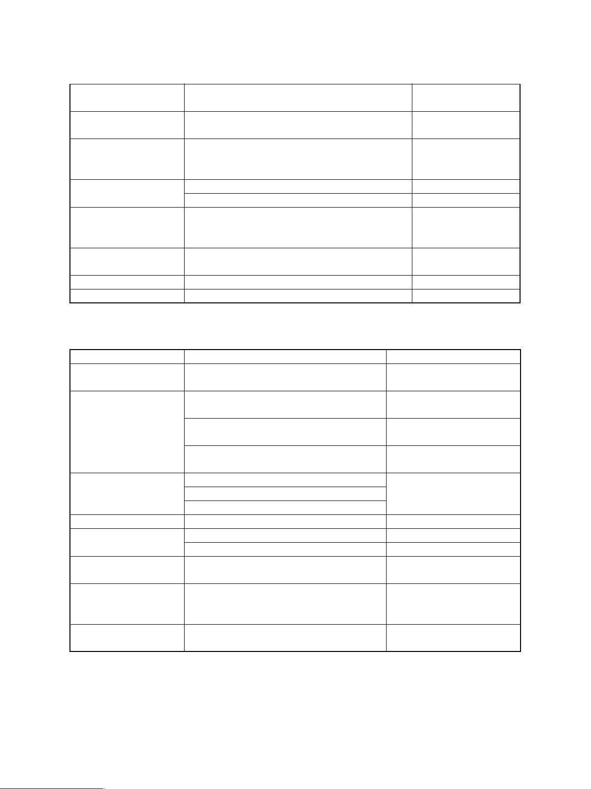
1.3. Options
ITEM MODEL NOTE
Large capacity paper feed tray AR-LC4
Finisher AR-F11
AR-F12 Saddle stitch finisher
Punch unit AR-PN3A 2 holes (φ6.5) Europe
AR-PN3B 2 holes/3 holes automatic selection(φ8.0) North America
AR-PN3C 4 holes (φ6.5) (80mm pitch) France
AR-PN3D 4 holes (φ6.5) (70, 21mm pitch) Sweden
Inserter AR-CF1
Printer kit AR-P15
AR-PK2
AR-PK3
AR-651/810 SPECIFICATIONS 1 - 13
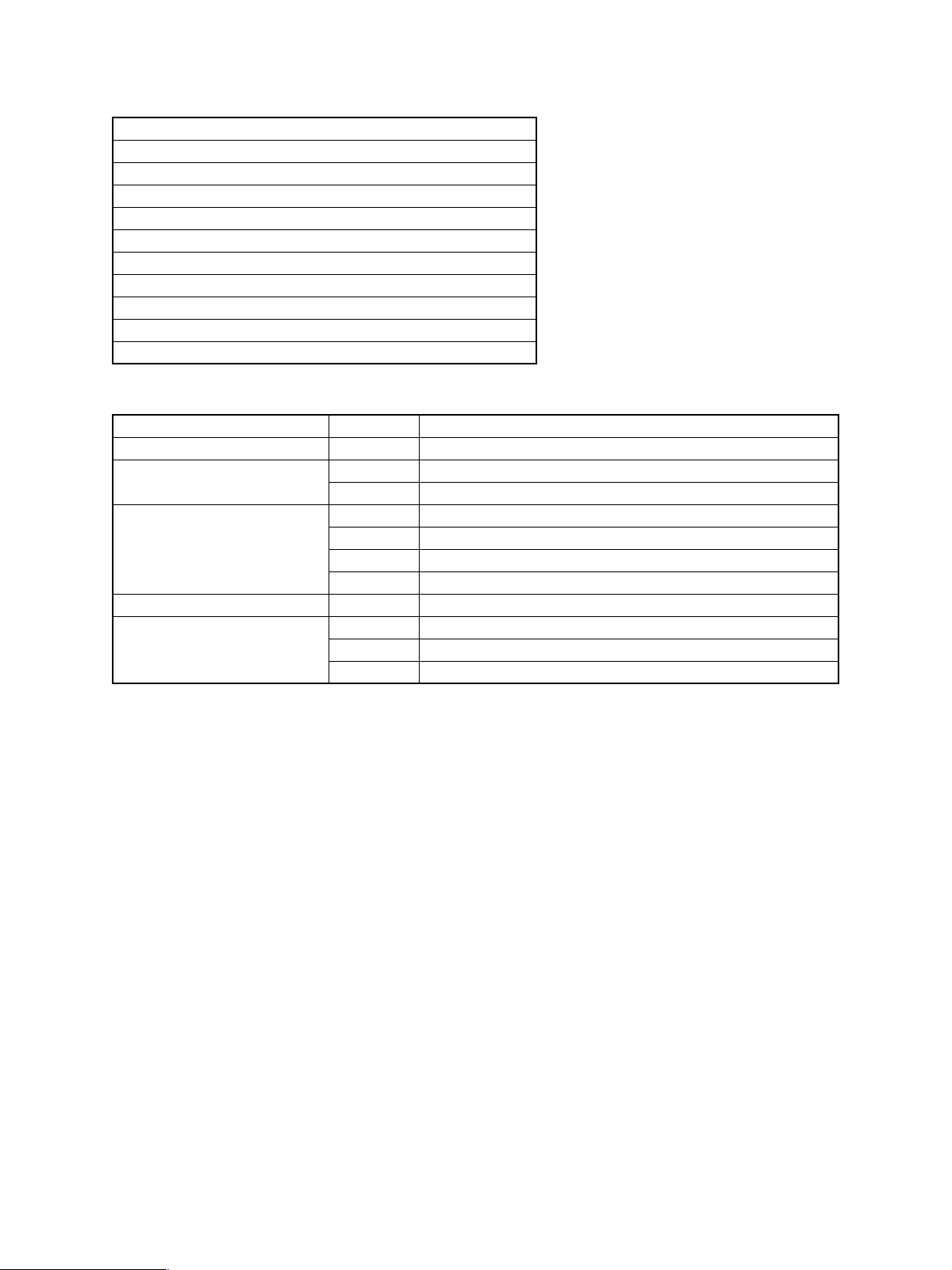
1.4. Supplies
SEC/SECL/(LAG)
No. Item Content Life Model Name
1 Toner CA (Black) Toner
(Toner; Net Weight 1350g)
2 Developer Developer
(Developer; Net Weight 1500g)
3 Drum Drum x 1 460K (AR-651)
Note 1) Master/individual cartons are printed in 2 languages (English/French).
Packaged for the machine: DR 460K/DV UN/Process UN
European Subsidiary
No. Item Content Life Model Name
1 Toner CA (Black) Toner
(Toner; Net Weight 1350g)
2 Developer Developer
(Developer; Net Weight 1500g)
3 Drum Drum x 1 460K (AR-651)
Note 1) Master/individual cartons are printed in 4 languages (English/French/Spanish/Germany).
Packaged for the machine: DR 460K/DV UN/Process UN
x 4 240k
(60K x 4)
x 1 460K (AR-651)
500K (AR-810)
500K (AR-810)
x 4 240k
(60K x 4)
x 1 460K (AR-651)
500K (AR-810)
500K (AR-810)
AR-810MT 1 * Life: A4 size at 6% AC
AR-810ND 4
AR-810DR 10
AR-810LT 1 * Life: A4 size at 6% AC
AR-810DV 4
AR-810DM 10
Packing
Unit
Packing
Unit
Remarks
MT=NT x 4
Remarks
MT=NT x 4
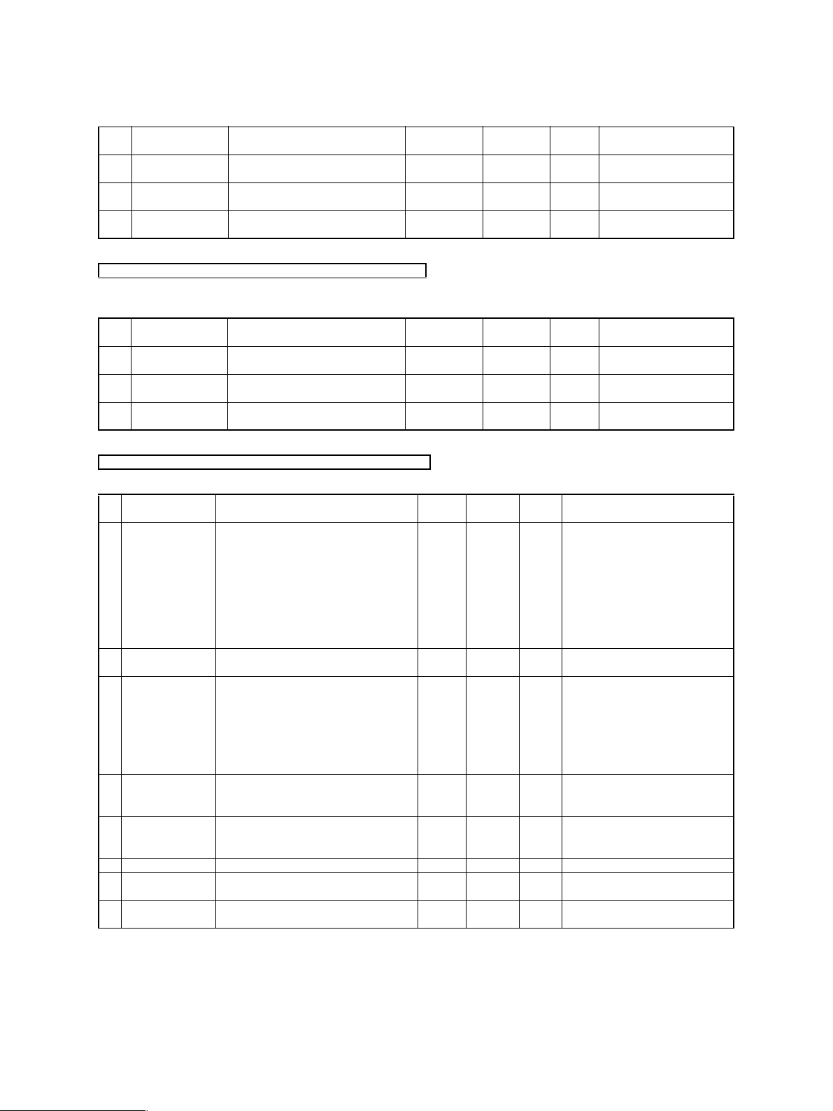
No. Item Content Life
1 Maintenance Kit 1 Drum cleaning blade x1
2 Maintenance Kit 2 Ozone filter x1 460K
3 Fusing Kit Heat roller upper x1
4 DF Kit Pick-up roller (ADF) x1
5 Roller Kit Pick-up roller (Main) x1
6 Waste toner bottle Waste toner bottle x4 AR-810HB 1 common between AR651 and AR810
7 Stapler for Finisher
5000 staples
8 Stapler for Saddle
Stitch 2000 staples
Note 1: NO.1 to 3 item --- AR651 (460K), AR810 (500K)
Note 2: Maintenance parts other than above items must be ordered through the parts department using the proper part number.
Note 3: No.1 to 6 items are UNCOMPATIBLE with existing machine
Drum separation claw x2
Drum cleaning roller x1
Charger wire (Main) x1
Charger wire cleaning pad x1
Charger grid x1
Transfer belt x1
Transfer belt brush roller x1
Transfer belt cleaning blade x1
Air filter (toner filter) x1
Hear roller lower x1
Upper separation claw x6
Cleaning web x1
Web press roller x1
Heat roller cleaning roller (Upper) x1
Heat roller cleaning roller (Lower) x1
Separation Roller (ADF) x1
Feed roller (Main) x1
Separation roller (Main) x1
Staple cartridge x3
Staple cartridge x3
460K
500K
500K
460K
500K
500K AR-810DF 1 common between AR651 and AR810Feed roller (ADF) x1
200K
350K
5000 x 3 SF-SC11 20
2000 x 3 AR-SC3 40
Model
Name
AR-810KA 1 common between AR651 and AR810
AR-810LC 1 common between AR651 and AR810
AR-810FU 1 common between AR651 and AR810
AR-810RT 1
Packing
Unit
common between AR651 and AR810
200K: Tray
350K: Tandem LCC
Common with S55,S55N,FN8/9
For AR-F12 (Saddle Stitch Finisher)
Remarks
Cartridge for AR-F11/12
Common with FN9
AR-651/810 SPECIFICATIONS 1 - 14
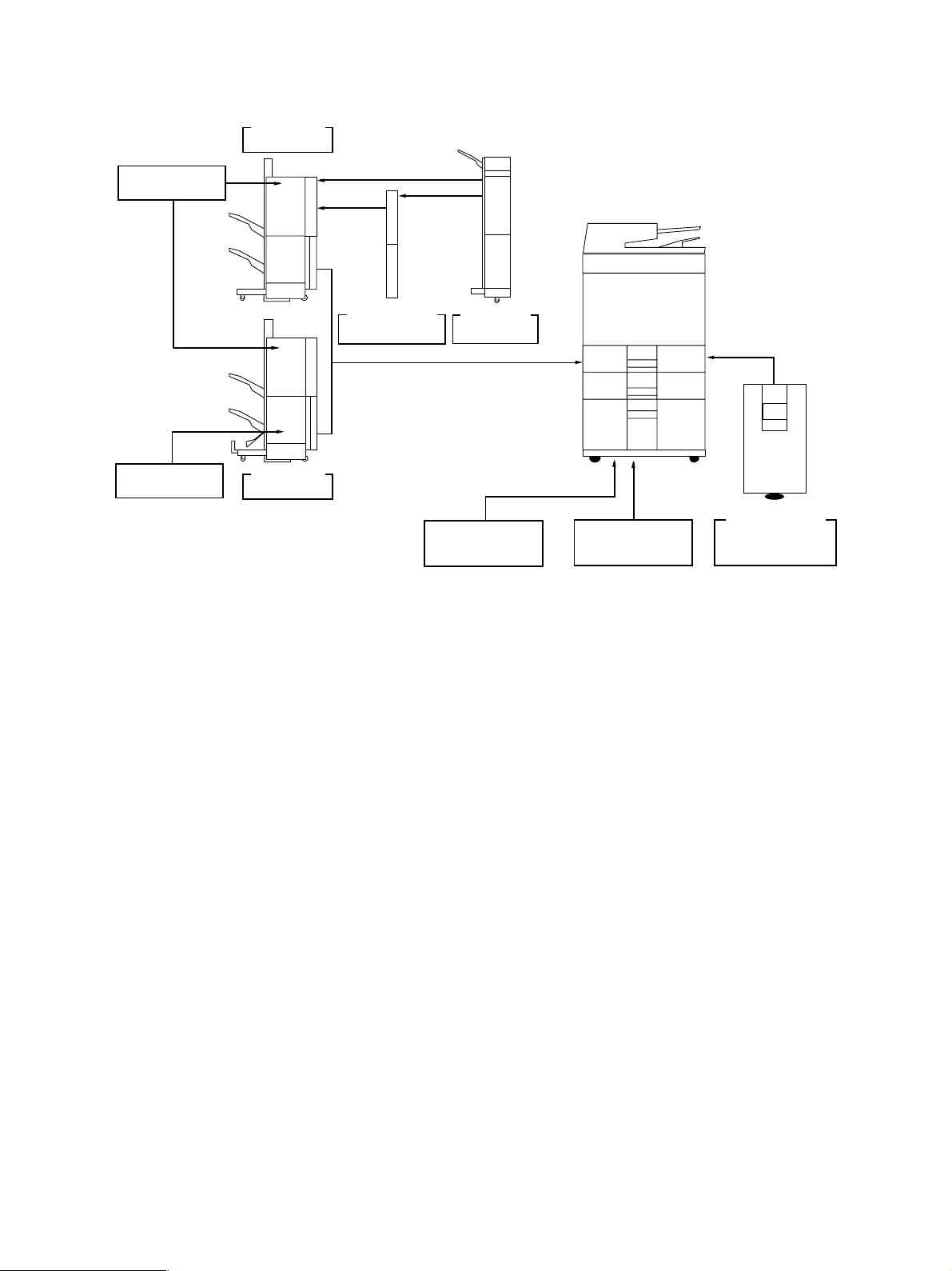
1.5. System List
Staple cartridge
AR-SC3
Finisher
AR-F11
Staple cartridge
SF-SC11
Finisher
AR-F12
Hole punch unit
AR-PN3
Inserter
AR-CF1
Printer controller
AR-PK2
AR-PK3
Printer board
AR-P15
LCF
AR-LC4
AR-651/810 SPECIFICATIONS 1 - 15
2. COMPONENT LAYOUT & FUNCTIONS
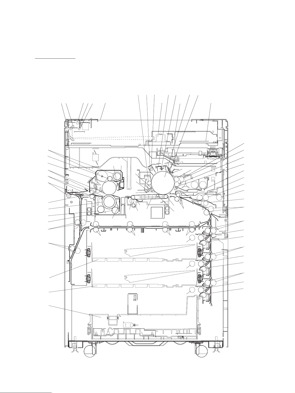
2. 1. Sectional View
[A] Front side view
32
33
34
35
36
43
44
37
38
39
45
46
5 6
4
21
3
47 48 49 50
40 41
42
19
17
18
16
30
31
1213
1415
7
10 11
89
20 21
26
272829
51
60
23A
23
22
24
25
52
54
55
53
56
57
58
59
61
69
70
71
64
68
AR-651/810 COMPONENT LAYOUT & FUNCTIONS 2 - 1
62
63
65
66
67

1 Exposure lamp
39 Cleaning roller (felt)
2 Reflector
3 Mirror 1
4 Mirror 2
5 Mirror 3
6 Original glass
7 Lens
8 CCD driving PC board
9 Scanner control PC board SLG
10 Drum
11 Drum thermistor
12 Charger wire cleaner
13 Main charger
14 Discharge LED
15 Drum cleaning blade
16 Drum cleaning brush
17 Drum recovery blade
18 Image quality sensor
19 Drum separation finger
40 Upper fuser roller thermistor
41 Thermostat
42 Pressure roller thermistor
43 Engine exit rollers
44 Reverse/exit switching gate
45 Reverse path rollers 1
46 Reverse path rollers 2
(Switch back rollers)
47 Transfer rollers 1
48 Transfer rollers 2
49 Transfer rollers 3
50 Transfer rollers 4
51 Registration rollers
52 Bypass transfer rollers
53 Bypass separation roller
54 Bypass feed roller
55 Bypass pickup roller
56 Intermeditate transfer rollers
20 Drum voltage sensor
21 Upper developer sleeve
22 Lower developer sleeve
(Magnetic roller)
(Magnetic roller
23 Transport sleeve
23A Doctor blade
24 Scattered toner recovery roller
25 Auto-toner sensor
26 Transfer belt driven roller (idler)
27 Transfer belt power supply roller
28 Transfer belt
29 Transfer belt drive roller
30 Transfer belt cleaning blade
31 Transfer belt cleaning brush
32 Fuser roller cleaning web
33 Cleaning web pushing roller
34 Upper fuser roller
35 Separation fingers
36 Fuser exit rollers
57 1st cassette transfer rollers
58 1st cassette feed roller
)
59 1st cassette separation roller
60 1st cassette pickup roller
61 2nd cassette transfer rollers
62 2nd cassette feed roller
63 2nd cassette separation roller
64 2nd cassette pickup roller
65 Tandem LCF transfer rollers
66 Tandem LCF feed roller
67 Tandem LCF separation roller
68 Tandem LCF cassette pickup roller
69 1st cassette
70 2nd cassette
71 Tandem LCF tray
37 Pressure roller
38 Cleaning roller (metal)
AR-651/810 COMPONENT LAYOUT & FUNCTIONS 2 - 2
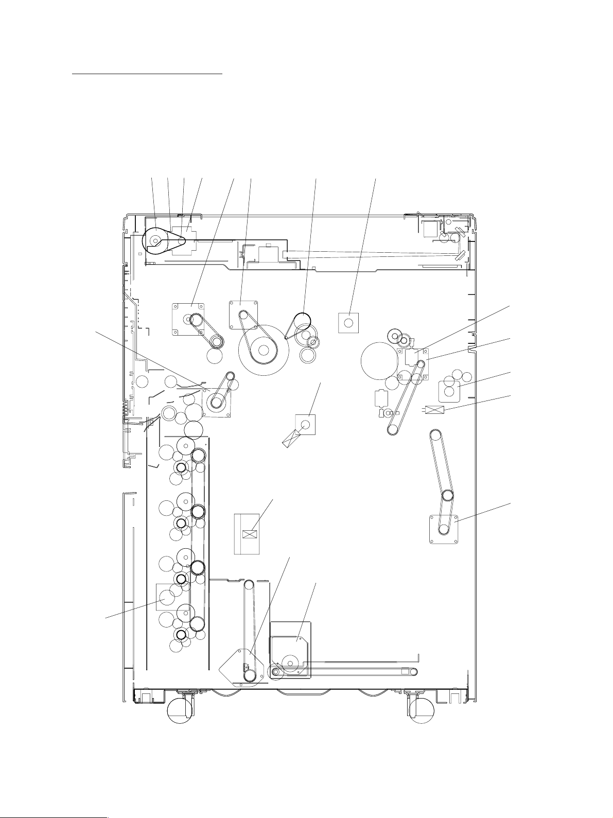
[B] Rear side view (Drive system)
1234
7
65 14 18
15
9
8
10
19
16
12
13
17
11
AR-651/810 COMPONENT LAYOUT & FUNCTIONS 2 - 3

1 Scanner motor
2 Drive pulley
3 Drive belt
4 Driven pulley
5 Drum motor
6 Developer unit motor
7 Registration motor
8 Fuser motor
9 Web motor
10 Exit motor
11 Reverse motor
12 LCF tray-up motor
13 LCF end fence motor
14 Cleaner brush motor
15 TX belt lift cam motor
16 Tray 1 & 2 paper lift motor
17 Paper feed motor
18 TX belt drive motor
19 Waste toner transport motor (TX belt)
AR-651/810 COMPONENT LAYOUT & FUNCTIONS 2 - 4
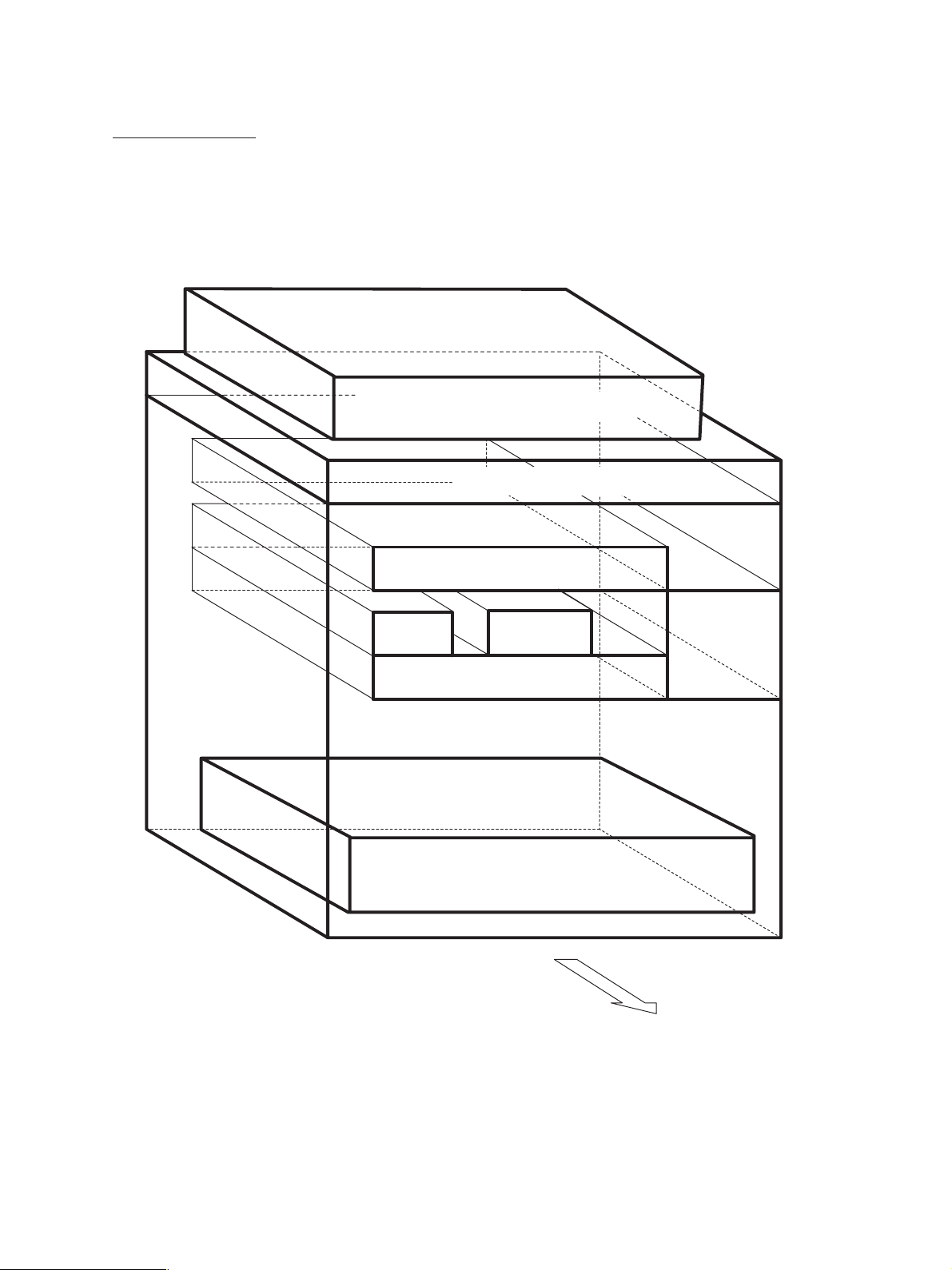
2. 2. Electric Parts Layout
[A] Unit construction
Reversing automatic document feeder unit
Scanner unit
Laser unit
DV
unit
Transfer/Transport unit
Copier unit
Process
unit
Tandem tray unit
Fuser unit
AR-651/810 COMPONENT LAYOUT & FUNCTIONS 2 - 5
Rear side
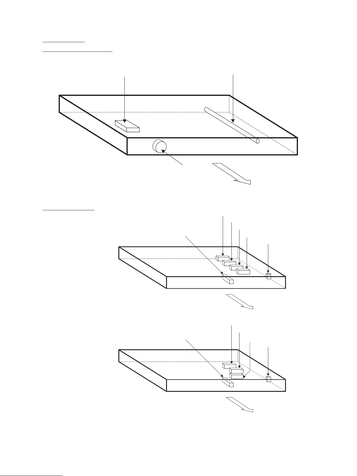
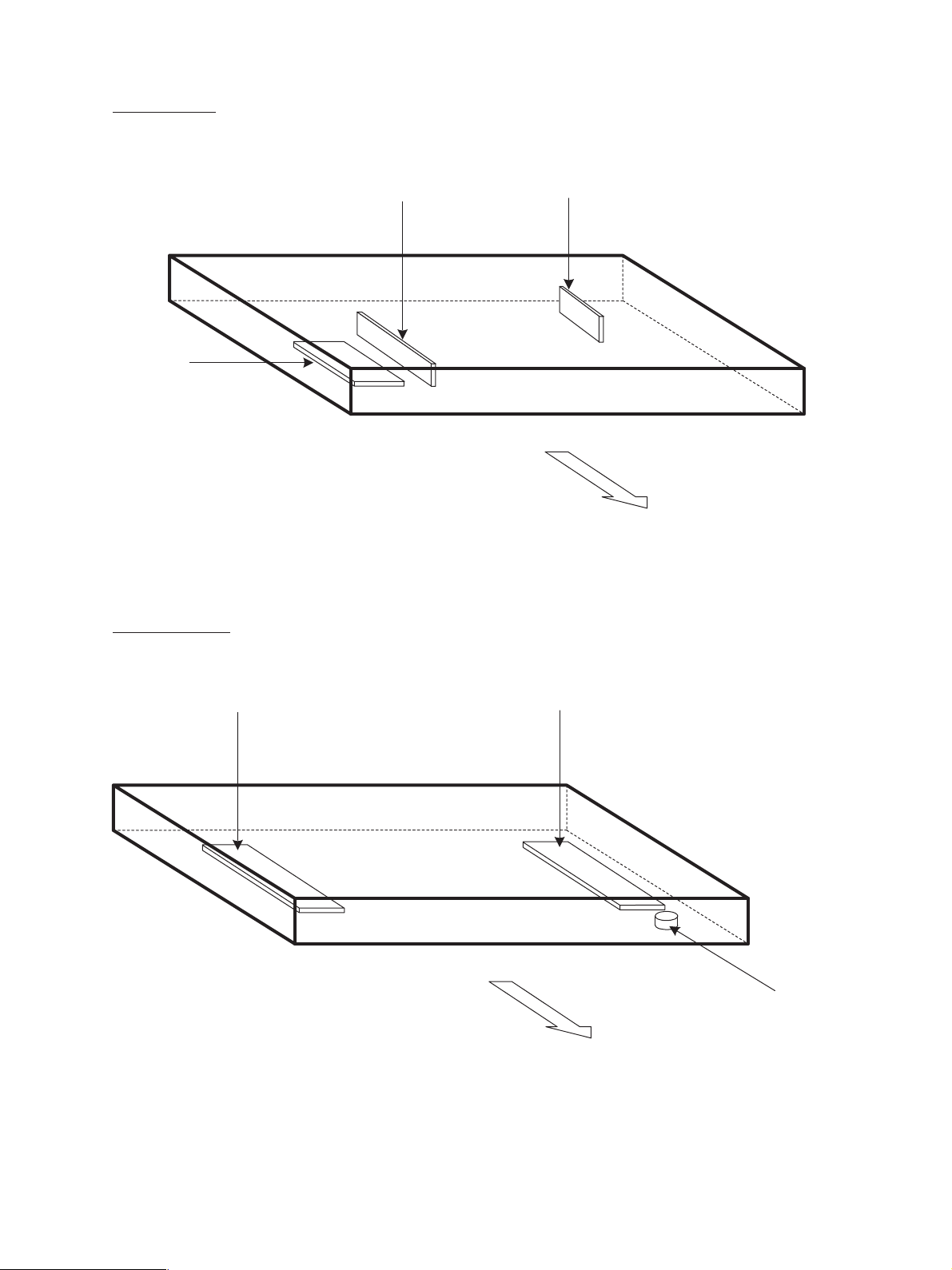
[B] Scanner unit
(B-1) Motor/Exposure lamp
(B-2) Sensor/Switch
A4 series
M31
M1
S1-5
EXP
Rear side
S1-2
S1-1
S1-3
S1-4
S2
LT series
S1-2
S1-3
S1-5
AR-651/810 COMPONENT LAYOUT & FUNCTIONS 2 - 6
Rear side
S1-4
S2
Rear side
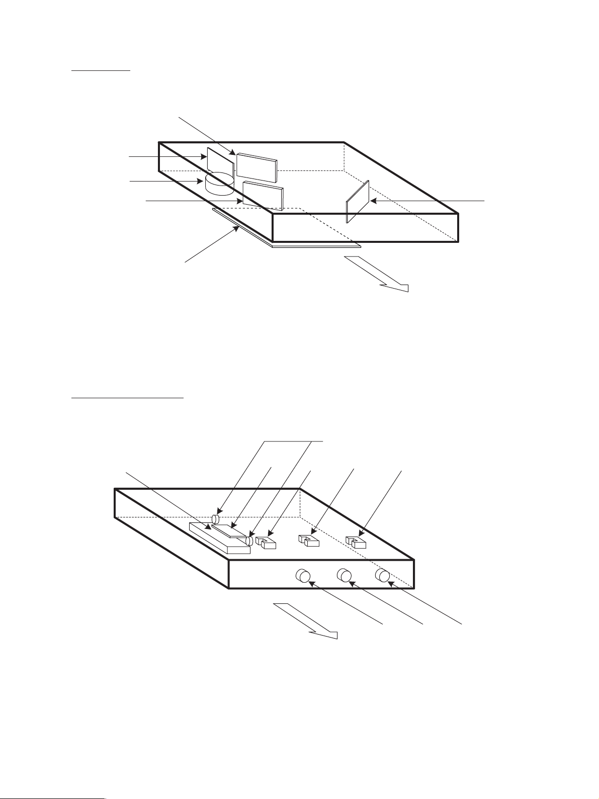
(B-3) PC board
SLG
(B-4) Other parts
CCD
INV
Rear side
DHR
DHL
THMO4
Rear side
AR-651/810 COMPONENT LAYOUT & FUNCTIONS 2 - 7
[C] Laser unit
LDR1
M2
GLV
LDR2
PLG
[D] Transfer/Transport unit
DHT
FUSE
S5
THMO3
S4
SNS
Rear side
S3
CLT3
Rear side
AR-651/810 COMPONENT LAYOUT & FUNCTIONS 2 - 8
CLT1CLT2

[E] Fuser unit
S6
THM1
THMO2
IH
S7
THM2
THMO1
M30
THM5
THM3
M3
IHCOIL
Rear side
AR-651/810 COMPONENT LAYOUT & FUNCTIONS 2 - 9
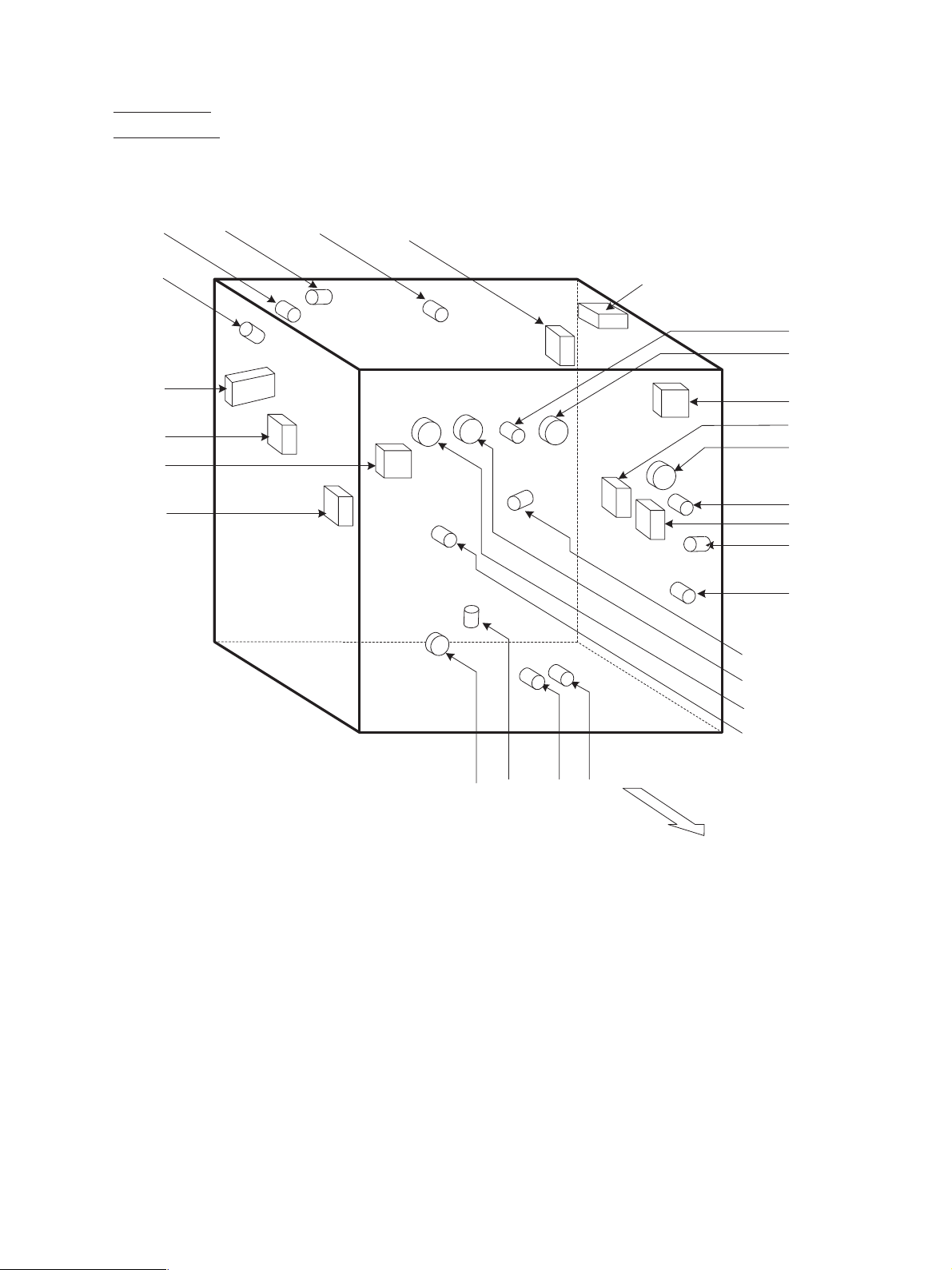
[F] Copier unit
(F-1) Motor/Fan
M19
M20
M26
M27
M28
M29
M18
M17
M25
M24
M16
M15
M21
M22
M14
M13
M23
M12
M11
M10
M9
M8
M6
M5
M4
AR-651/810 COMPONENT LAYOUT & FUNCTIONS 2 - 10
M32
M7
Rear side
 Loading...