

Page 1

MODEL
oo
65
oDISPLAY
oo
LC-65G5X
AVC SYSTEM
TU-65GAX
LCD COLOUR TELEVISION
OPERATION MANUAL
Page 2

LC-65G5X
TU-65GAX
LCD COLOUR TELEVISION
ENGLISH
OPERATION MANUAL
Contents
Contents …………………………………………………… 1
Dear SHARP customer …………………………………… 3
Trademarks ………………………………………………… 3
Important Safety Precautions ………………………… 4
Supplied accessories …………………………………… 5
Preparation ………………………………………………… 6
Where to place the System…………………………… 6
Setting the System …………………………………… 7
Setting the AVC System with the stand …………… 9
Setting the Display on the wall ……………………… 10
Removing the stand …………………………………… 11
Removing speakers …………………………………… 11
Inserting the batteries ………………………………… 12
Using the remote control unit ………………………… 12
Cautions regarding remote control unit ……… 12
Basic connection ……………………………………… 13
Connecting to an antenna ……………………… 13
Connecting to the power outlet ………………… 13
Part names ………………………………………………… 14
Display ………………………………………………… 14
AVC System …………………………………………… 15
Remote control unit …………………………………… 16
Watching TV ……………………………………………… 17
Turning on the power ………………………………… 17
Turning off the power ………………………………… 17
Simple button operations for changing channels … 18
Using Flashback (A) on the remote control unit … 18
Using MPX on the remote control unit ……………… 19
Simple button operation for changing
volume/sound …………………………………… 20
Basic adjustment settings ……………………………… 21
Menu operation buttons ……………………………… 21
On-Screen Display …………………………………… 21
TV/AV input mode menu items ……………………… 22
PC input mode menu items ………………………… 22
Auto installation ……………………………………… 23
Programme setup……………………………………… 23
Auto search ……………………………………… 23
Manual setting for each channel ……………… 24
Search tuning………………………………… 24
Fine tuning …………………………………… 24
Colour system ……………………………… 25
Sound system (Broadcasting system) …… 25
Labelling channels ………………………… 25
Skipping channels ………………………… 26
Setting the child lock ……………………… 26
Password setting for child lock (for TV input
mode) See page 56.
Setting the booster ………………………… 26
Sort ………………………………………………… 27
Erase Programme ………………………………… 27
ENGLISH
Language setting for on-screen display …………… 28
OPC (Optical Picture Control) setting ……………… 28
Picture adjustments …………………………………… 29
Advanced ……………………………………………… 30
C.M.S. (Colour Management System) ………… 30
Colour temperature ……………………………… 30
Sharpness Enhancement ……………………… 30
Automatic Contrast ……………………………… 30
I/P setting ………………………………………… 31
Film mode ………………………………………… 31
3D-Y/C …………………………………………… 31
Monochrome ……………………………………… 31
Audio adjustment ……………………………………… 32
Dolby Virtual ……………………………………… 32
Power control ………………………………………… 33
Power control for AV source …………………… 33
Power control for PC source …………………… 33
Using memory card ……………………………………… 34
Important notes on using memory cards …………… 34
Card Setup mode menu items ……………………… 36
Recording a still image ……………………………… 37
Displaying a still image ……………………………… 38
Displaying slide show ………………………………… 38
Setting Slide Show …………………………………… 38
My Programme ………………………………………… 39
Audio Select …………………………………………… 39
Protecting/unprotecting still image files …………… 39
Deleting a still image file ……………………………… 40
Deleting all still image files …………………………… 40
Recording a motion picture ………………………… 40
Displaying a motion picture ………………………… 41
Rec. Mode ……………………………………………… 41
Pre-recording ………………………………………… 41
Repeat ………………………………………………… 41
Protecting/unprotecting motion picture files ……… 42
Deleting a motion picture file ………………………… 42
Deleting all motion picture files ……………………… 42
Format ………………………………………………… 42
1
Page 3

Contents
Using external equipment ……………………………… 43
Displaying an external equipment image ………… 43
Displaying a DVD image (Example) ………………… 43
When connecting a game console using
composite cable ………………………………… 44
When connecting a VCR using S-video cable …… 44
When connecting a DVD player or an HDTV tuner
using component cable ………………………… 45
Connecting a game console or camcorder ………… 45
Connecting a PC ……………………………………… 46
Speaker Setup ………………………………………… 47
Connecting external speakers ………………… 47
Selecting speakers ……………………………… 47
Useful adjustment settings ……………………………… 48
Useful features …………………………………………… 58
Appendix ………………………………………………… 62
Dimensional drawings …………………………………… 69
External Audio Bypass ………………………… 47
Image position (for TV/AV input mode) ……………… 48
Audio Only ……………………………………………… 48
Auto Sync. adjustment (PC input mode only) ……… 48
Fine Sync. adjustment (PC input mode only) ……… 49
Input Select …………………………………………… 49
Input Label …………………………………………… 50
Colour system setting (for TV/AV input mode) …… 50
AV mode selection …………………………………… 51
Wide Screen Signalling (WSS)
(for TV/AV input mode)…………………………… 51
Picture aspect ratio (for TV/AV input mode) ……… 51
WIDE mode (for TV/AV input mode) ………………… 52
WIDE mode (for PC input mode) …………………… 53
Input signal (PC input mode only) …………………… 54
3D-NR (3D Noise Reduction) ………………………… 54
Quick Shoot …………………………………………… 54
Rotate …………………………………………………… 54
Mosquito Noise Reduction …………………………… 55
Audio out ……………………………………………… 55
Sleep timer …………………………………………… 55
Password setting for child lock
(for TV input mode) ……………………………… 56
Centre Channel Input ………………………………… 57
Dual screen functions ………………………………… 58
Teletext language setting …………………………… 59
Teletext function ……………………………………… 60
Troubleshooting ……………………………………… 62
PC compatibility chart ………………………………… 63
Connecting pin assignments for SCART …………… 63
RS-232C port specifications ………………………… 64
Specifications ………………………………………… 66
Optional accessory …………………………………… 66
Protection against overturning ……………………… 67
2
Page 4

Dear SHARP customer
Thank you for your purchase of the SHARP LCD colour TV product. To ensure safety and many years of troublefree operation of your product, please read the Important Safety Precautions carefully before using this product.
Trademarks
Manufactured under license from Dolby Laboratories. “Dolby”, “Pro Logic” and the double-D symbol are trademarks
of Dolby Laboratories.
• Manufactured under license from BBE Sound, Inc.
Licensed by BBE Sound, Inc. under USP5510752 and 5736897. BBE and BBE symbol are registered trademarks
of BBE Sound, Inc.
• BBE Mach3Bass extends the bass response of a given loudspeaker and provides deep, tight and musically
accurate bass frequencies.
3
Page 5
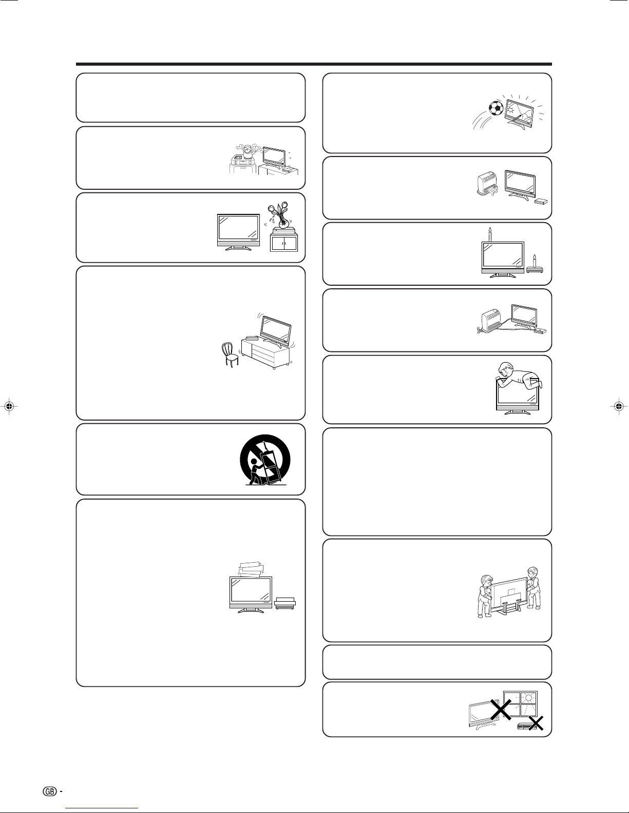
Important Safety Precautions
• Cleaning—Unplug the AC cord from the AC outlet
before cleaning the product. Use a damp cloth to
clean the product. Do not use liquid cleaners or
aerosol cleaners.
• Water and moisture—Do not use
the product near water, such as
bathtub, washbasin, kitchen sink,
laundry tub, swimming pool and in
a wet basement.
• Do not place vases or any other
water-filled containers on this
product.
The water may spill onto the
product causing fire or electric
shock.
• Stand—Do not place the product
on an unstable cart, stand, tripod
or table. Doing so can cause the
product to fall, resulting in serious
personal injuries as well as
damage to the product. Use only
a cart, stand, tripod, bracket or
table recommended by the
manufacturer or sold with the
product. When mounting the
product on a wall, be sure to
follow the manufacturer’s
instructions. Use only the
mounting hardware recommended
by the manufacturer.
• The LCD panel used in this
product is made of glass.
Therefore, it can break when the
product is struck forcefully or with
a sharp object. If the LCD panel is
broken be careful not to be injured
by broken glass.
• Heat sources—Keep the product
away from heat sources such as
radiators, heaters, stoves and
other heat-generating products
(including amplifiers).
• To prevent fire, never place any
type of candle or naked flames on
the top or near the TV set.
• To prevent fire or shock hazard,
do not place the AC power cord
under the TV set or other heavy
items.
• Do not place heavy objects on this
product or stand on it. Doing so could
cause injury if the product overturns.
Take special care near children and
pets.
• When relocating the product
placed on a cart, it must be
moved with utmost care. Sudden
stops, excessive force and
uneven floor surface can cause
the product to fall from the cart.
• Ventilation—The vents and other
openings in the cabinet are
designed for ventilation. Do not
cover or block these vents and
openings since insufficient
ventilation can cause overheating
and/or shorten the life of the
product. Do not place the product
on a bed, sofa, rug or other similar
surface, since they can block
ventilation openings. This product
is not designed for built-in
installation; do not place the
product in an enclosed place
such as a bookcase or rack,
unless proper ventilation is
provided or the manufacturer’s
instructions are followed.
The LCD panel is a very high technology product
with 6,220,800 thin film transistors, giving you fine
picture details.
Due to the very large number of pixels,
occasionally a few non-active pixels may appear
on the screen as a fixed point of blue, green or
red.
This is within product specifications and does not
constitute a fault.
Precautions when
transporting the Display
When transporting the Display,
never carry it by holding onto the
speakers. Be sure to always
carry the Display by two people
holding it with two hands—one
hand on each side of the display.
Do not display a still picture for a long time, as
this could cause an afterimage to remain.
• Selecting the location—Select a
place with no direct sunlight and
good ventilation.
4
Page 6
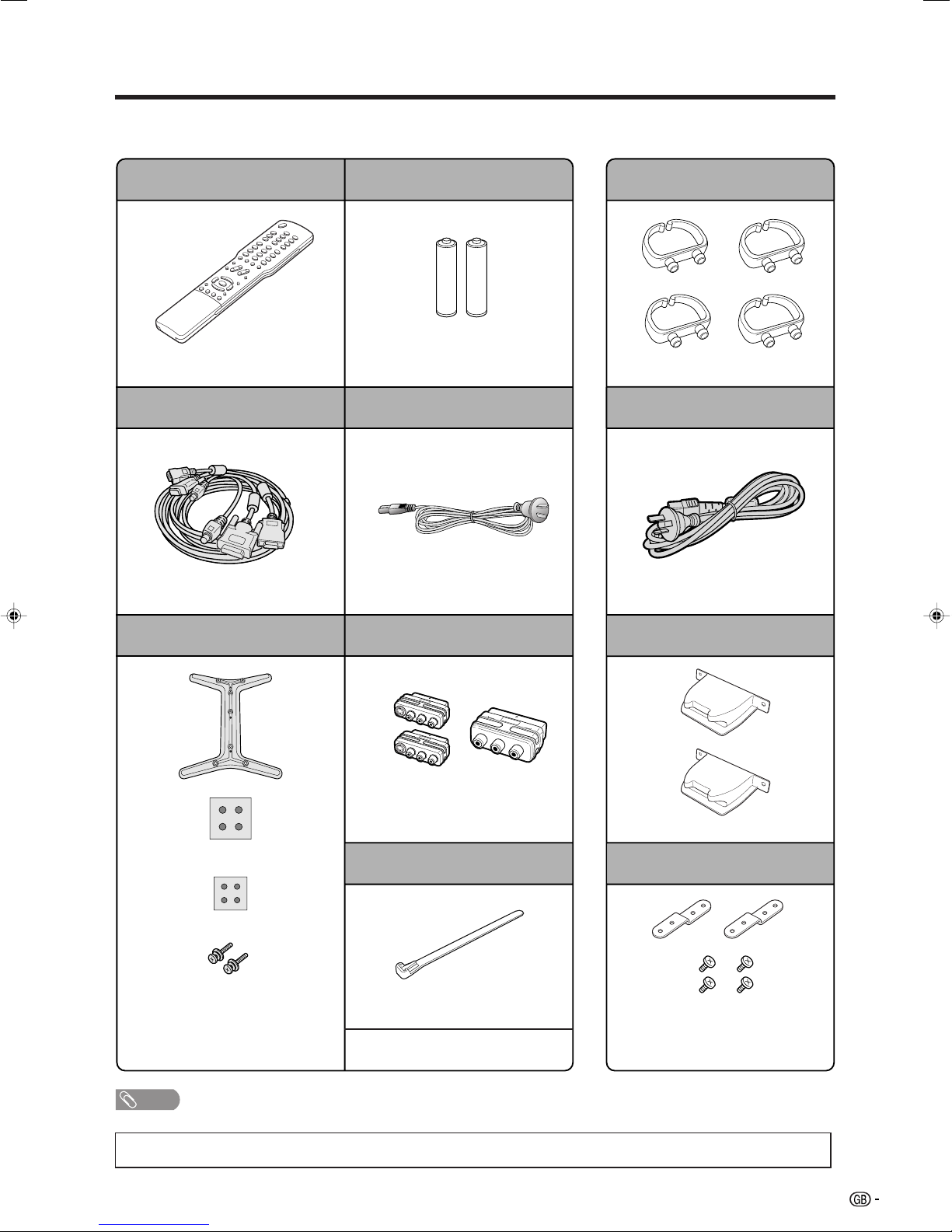
Supplied accessories
Make sure the following accessories are provided with the product.
AVC System Display
Remote control unit
Page 12
System cable
Page 7
Stand unit (for AVC System)
“AAA” size battery (g2)
Page 12
AC cord
Page 7
RCA/SCART conversion connector
(g3)
Cable clamp (g4)
Page 8
AC cord
Page 7
Stand hole cover (g2)
Stand (g1)
Stand cushion (g4)
Stand spacer (g4)
Stand screw (g2)
Page 9
NOTE
• Always use the AC cord supplied with the product.
• The illustrations and on-screen displays in this operation manual are for explanation purposes and may vary slightly
from the actual operations.
For INPUT2
and 3 (g2)
Pages 44 and 45
Cable tie (g1)
Page 7
• Operation manual
For INPUT1
(g1)
Page 11
Safety restraints
Restraining band (g2)
Screw for band (g4)
Page 67
5
Page 7

Preparation
Where to place the System
“System” means the Display and AVC System. First select the location where to place the System.
1
2
Selecting the location of the System
• Select a place with no direct sunlight and good ventilation.
• Select a place where it is flat and without a slope.
• The Display and the AVC System are connected by the system cable.
(See page 7 for details.)
System cable
Display AVC System
Setting the System in place
Handling the Display
CAUTION
• When using the Display with the supplied stand attached, do not remove the speaker. Doing
so may disturb the balance leading to product damage or personal injury.
• Do not remove the stand and speaker from the Display unless using an optional bracket to mount
it.
• Keep enough space above and behind the Display.
• When you move the System, carry it by two or more people.
• When you move the Display, hold the portion of the Display, not the speaker.
Handling the AVC System
CAUTION
• Do not put a VCR or other device on the AVC System.
• Keep enough space above and on the sides of the AVC System.
• Do not block the ventilation openings on the top and left side, and the exhaust fan on the right
side.
• Do not spread a thick cloth beneath the AVC System, or cover it with one, as this can cause
overheating and result in malfunction.
10 cm
or more
6
Keep enough space
5 cm or more
5 cm or more
on both sides
There is an exhaust fan
on the right side.
Page 8
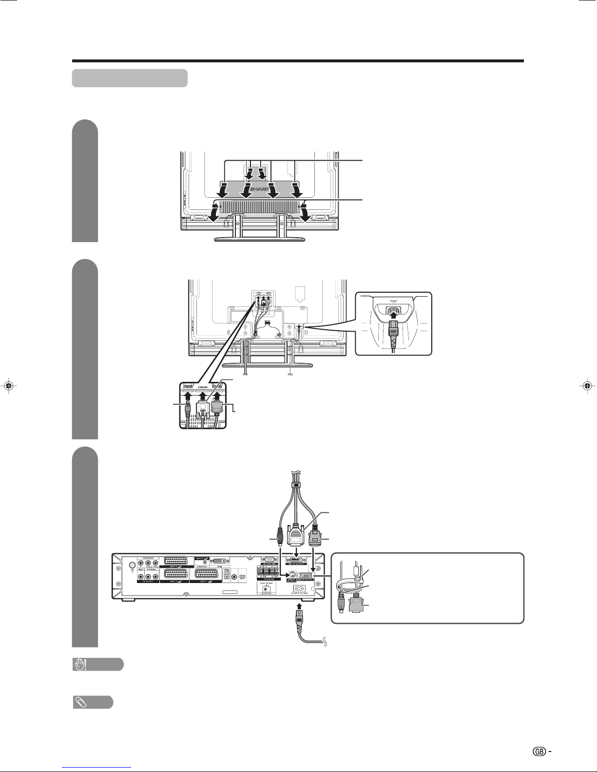
Preparation
Setting the System
After putting the Display and the AVC System in place, connect the system cables and AC cords. Use the
cable clamps for bundling the cables.
1
Removing the terminal cover
Display (rear view)
Press down the six
upper hooks to remove
the cover toward you.
Press the two hooks
toward the centre of the
Display and remove the
cover toward you.
2
Connecting the system cable and the AC cord to the Display
(WHITE)*
Connect the plug into the terminal and secure
(BLACK)
System cable
it by tightening the thumb screws.
(GREY)**
Connect the plug firmly until the hooks on
both sides click.
AC Cord
• Plug in the AC cord
completely into the
terminal.
3
Connecting the system cable and the AC cord to the AVC System
• Check the alignment of the
terminals before inserting.
(BLACK)
System cable
(WHITE)*
(GREY)**
AVC System (rear view)
Cable tie
(BLACK)
(GREY)
AC cord
CAUTION
• TO PREVENT RISK OF ELECTRIC SHOCK, DO NOT TOUCH UN-INSULATED PARTS OF ANY CABLES WITH THE
AC CORD CONNECTED.
NOTE
* When you unplug the WHITE system cable, make sure you unscrew the screws thoroughly before unplugging the cable.
** When you unplug the GREY system cable, press the hooks on both sides of the cable inward as you unplug the cable gently.
Tie up the black and grey
cables after inserting
system cables. (Follow
instructions for preventing
cables being pulled out.)
System cable
7
Page 9
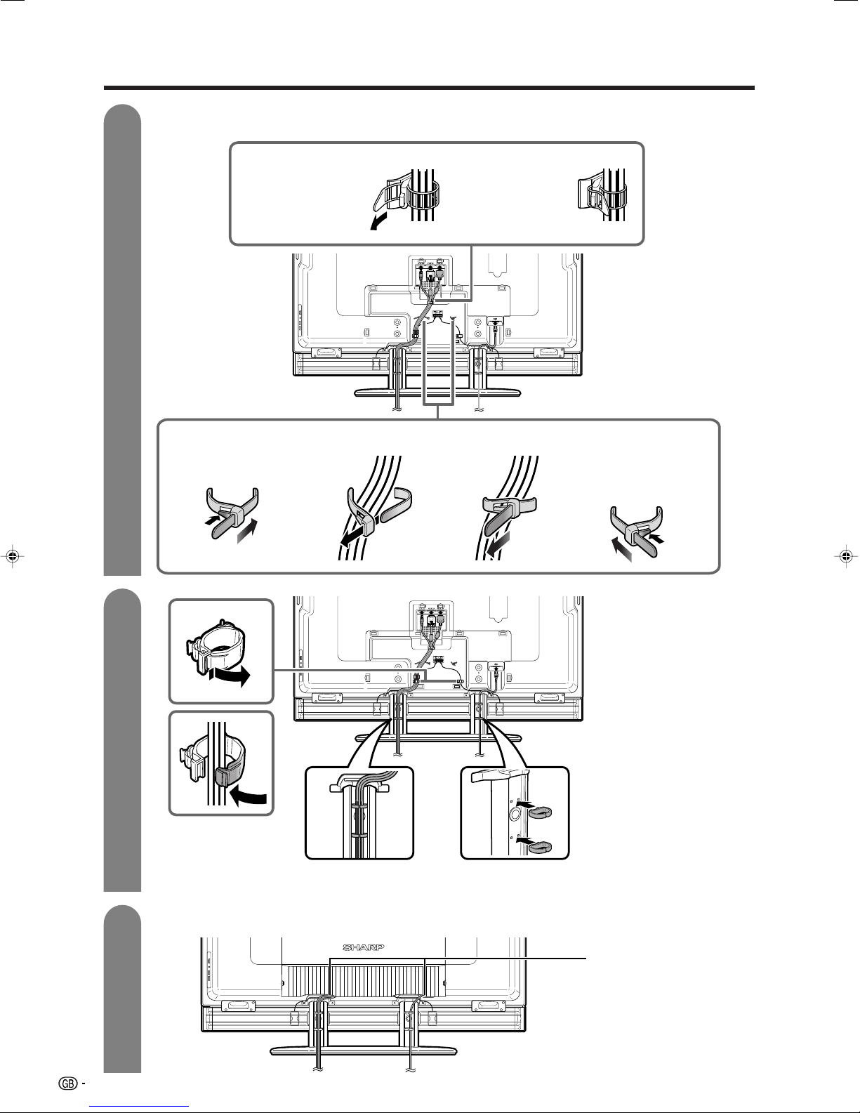
Preparation
4
Attaching the clamp and bundling the cables with the clamp
Fit the band around system cables.
1 Pass the end of the
band through the
hole.
Fix the system cables firmly to the Display as shown.
2 Pull the band
toward you and
fasten to the tab.
* If routing the cables on the
right side, use the holder on
the right. You need to
reverse the direction of the
holder when routing the
cables on the right side.
5
Fasten the cables with
the holder.
* If routing the cables on
the right side, use the
holder on the right.
6
Closing the terminal cover
Cable clamp
Insert the cable clamp in the hole on the Display as shown.
Cables come out from
the small opening.
8
Page 10
Preparation
Setting the AVC System with the stand
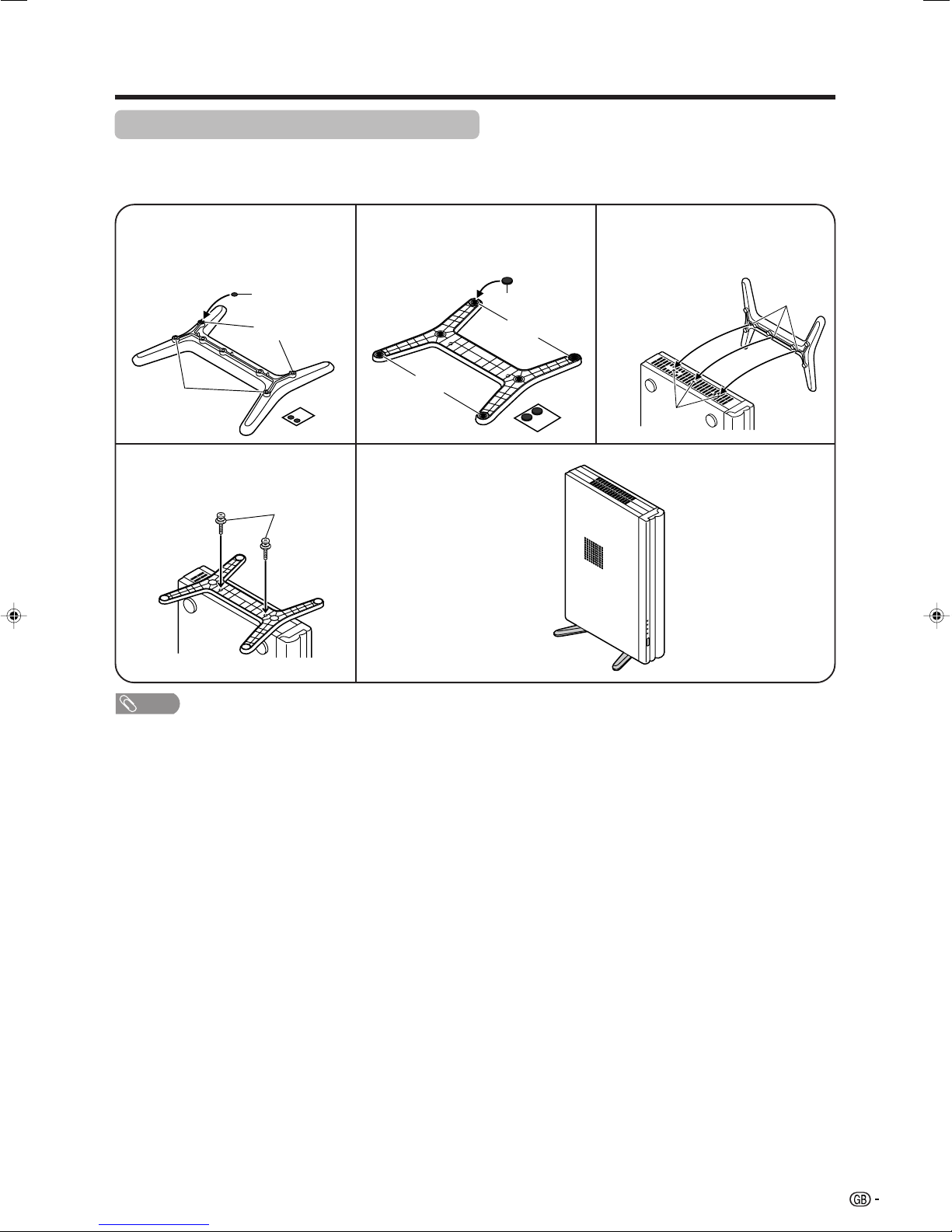
How to install the AVC System vertically using the stand unit
• Use the supplied stand unit for installing the AVC System vertically in an upright position.
Stick each spacer to the
stand as shown.
1
Peel each spacer away from the paper
and attach to the four bulging areas
on the stand.
Bulge
Stand
spacer
Bulge
Attach the stand using the
stand screws as shown.
4
Stand screw
Attach each cushion to
the stand as shown.
2
Peel each cushion
away from the
paper and attach
to the four areas
at the bottom.
Attaching point
Stand cushion
Attaching point
The AVC System installed
vertically with the stand.
Fit the stand to the AVC
System.
3
Insert the stand into the AVC
System, making sure that the
thick and thin bulges of the
stand align with the big and
small holes on the AVC
System.
Hole
Bulge
NOTE
• When mounting the AVC System vertically, always use the supplied stand. Be careful not to block vent holes when
standing up directly on the floor or a flat surface as this can result in equipment failure.
9
Page 11
Preparation
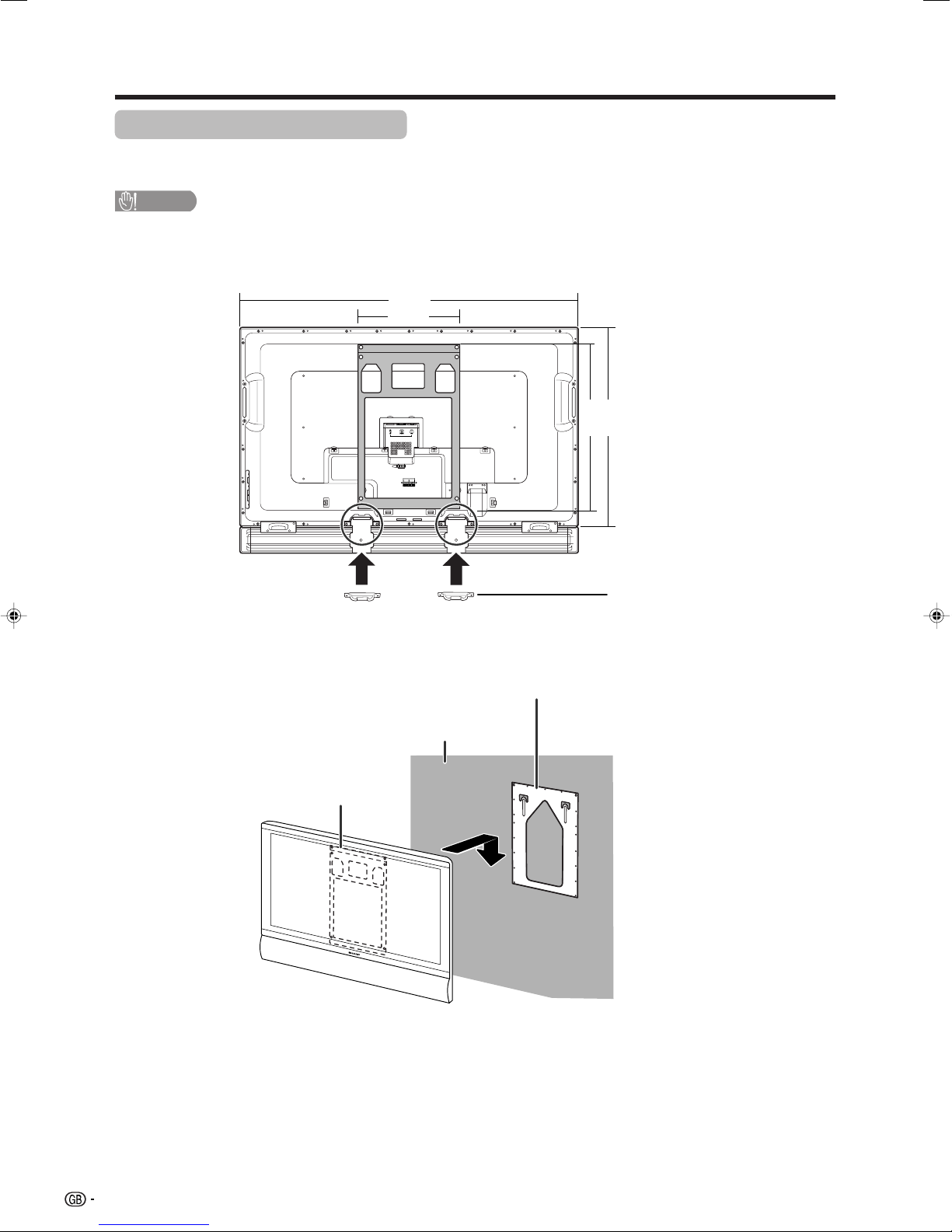
Setting the Display on the wall
• You can mount the Display on the wall, using the optional AN-65AG1 bracket.
• For details, refer to the instructions supplied with the optional bracket.
CAUTION
• Installing the Display requires special skill that should only be performed by qualified service personnel. Customers
should not attempt to do the work themselves. SHARP bears no responsibility for improper mounting or mounting
that results in accident or injury.
1572
558
(mm)
767
923
• Be sure to attach the stand hole
covers (supplied) after detaching
the stand.
Wall mount bracket
Attach the stand hole covers
(supplied) with four screws (edge
cover screws). (For details, refer to
the AN-65AG1 operation manual.)
Base bracket
Wall
10
Page 12
Preparation
Removing the stand
Before detaching (or attaching) stand, unplug the AC cord from the AC input terminal and the system cable
from the Display.
CAUTION
• Do not remove the stand and speaker from the Display unless using an optional bracket to mount it.
Before attaching/detaching stand
• Before performing work, make sure to turn off the System.
• Before performing work, spread cushioning over the base area to lay the Display on. This will prevent it from
being damaged.
1
Unfasten the four screws
used to secure the bracket
in place.
NOTE
• To attach the stand, perform the above steps in reverse order.
2
Unfasten the eight screws
used to secure the stand
in place.
3
Detach the stand from the
Display. (Hold the stand so
it will not drop from the
edge of the base area.)
Removing speakers
1
3
4
Attach the stand hole
covers (supplied with the
product).
Take off the speaker terminal cover.
2
Disconnect the cable from the speaker.
CAUTION
• Do not remove the stand and speaker from the Display unless using an optional bracket to mount it.
• Before performing work, spread cushioning over the base area to lay the Display on. This will prevent it from
being damaged.
NOTE
• To attach the speaker, perform the steps in reverse order.
• Perform the same steps for the left section of the speaker.
Unfasten the screws.
1
2
1
11
Page 13

Preparation
Inserting the batteries
Before using the System for the first time, insert two “AAA” size batteries (supplied). When the batteries become
depleted and the remote control fails to operate, replace the batteries with new “AAA” size batteries.
1 Open the battery cover. 2 Insert two supplied “AAA” size
batteries.
• Place batteries with their terminals
corresponding to the (e) and (f)
indications in the battery compartment.
CAUTION
Improper use of batteries can result in chemical leakage or explosion. Be sure to follow the instructions below.
• Do not mix batteries of different types. Different types of batteries have different characteristics.
• Do not mix old and new batteries. Mixing old and new batteries can shorten the life of new batteries or cause
chemical leakage in old batteries.
• Remove batteries as soon as they have worn out. Chemicals that leak from batteries can cause a rash. If you
find any chemical leakage, wipe thoroughly with a cloth.
• The batteries supplied with this product may have a shorter life expectancy due to storage conditions.
• If you will not be using the remote control unit for an extended period of time, remove the batteries from it.
3 Close the battery cover.
Using the remote control unit
Use the remote control unit by pointing it towards the
remote sensor window. Objects between the remote control
unit and sensor window may prevent proper operation.
Cautions regarding remote control unit
• Do not expose the remote control unit to shock.
In addition, do not expose the remote control unit to liquids, and do not
place in an area with high humidity.
• Do not install or place the remote control unit under direct sunlight.
The heat may cause deformation of the unit.
• The remote control unit may not work properly if the remote sensor window
of the Display is under direct sunlight or strong lighting. In such case, change
the angle of the lighting or Display, or operate the remote control unit closer
to the remote sensor window.
30˚
5 m
30˚
Remote
control
sensor
12
Page 14
Preparation
Simple operations for watching a TV programme
Basic connection
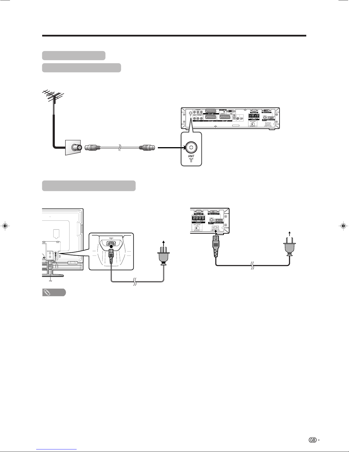
Connecting to an antenna
To enjoy a clearer picture, use an outdoor antenna. The following is a brief explanation of the types of connections
that are used for coaxial cable.
AVC System (rear view)
Standard DIN45325 plug (IEC169-2)
75-ohm coaxial cable (round cable)
Antenna cable
(Commercially available)
Connecting to the power outlet
Before connecting the AC cords, make sure to connect the system cable first.
Display (rear view)
AVC System (rear view)
AC outlet
AC outlet
NOTE
• Always turn off the main power of Display when connecting the AC cords.
• Disconnect the AC cords from the AC outlet, Display and AVC System if the System will not be used for a long period of
time.
13
Page 15
Part names
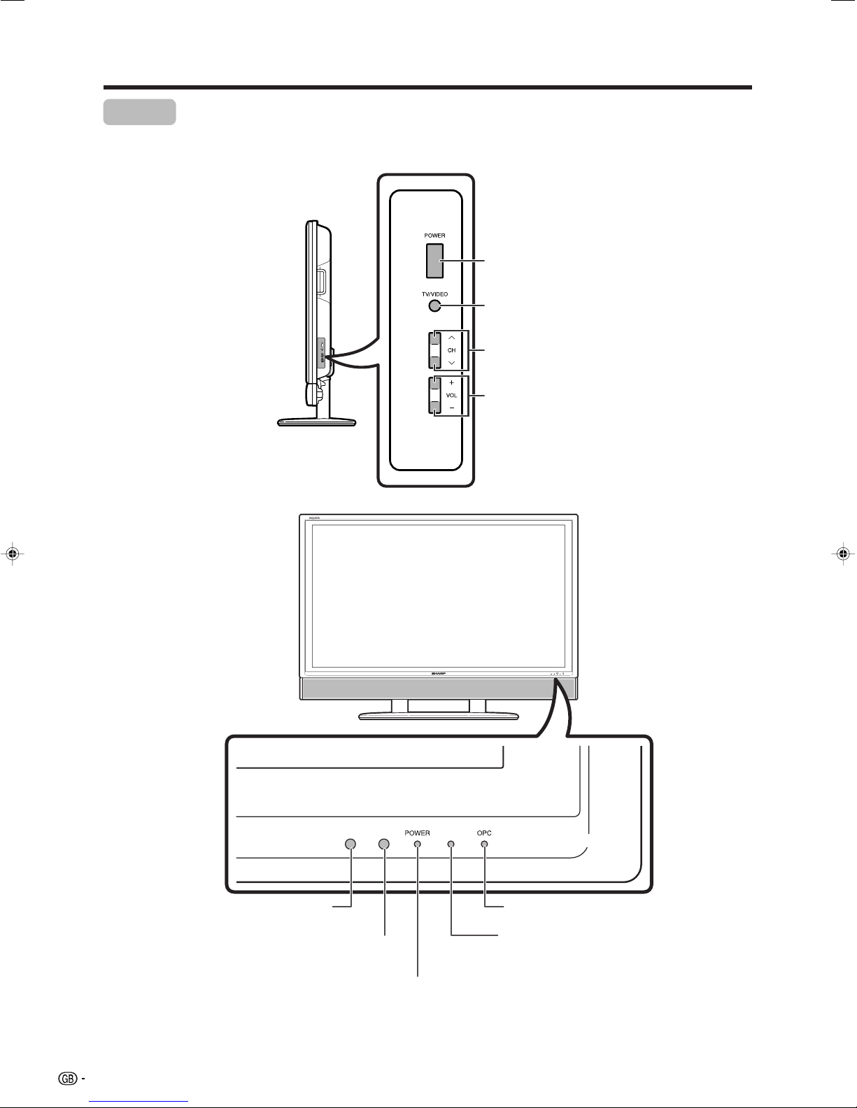
Display
POWER (On/Off) button
TV/VIDEO button
Channel up (r)/down (s) buttons
Volume up (k)/down (l) buttons
Remote control sensor
14
OPC sensor*
POWER indicator
OPC indicator
Remote control indicator
*OPC: Optical Picture Control
(See page 28.)
Page 16
Part names
AVC System
Front view
POWER indicator
POWER button
Headphone
(When connecting headphones, the sound from the speakers is muted.)
CARD indicator
RESET*
INPUT 4 terminal (VIDEO)
INPUT 4 terminal
(S-VIDEO)
SYSTEM RESET**
PC CARD slot
INPUT 4 terminal (AUDIO L/R)
How to open the door.
* Press RESET if the System cannot return to its original state after performing various operations.
This will reset the System as shown below.
• “AV MODE” resets to “USER”.
• TV channel resets to channel 1.
• Dual screen resets to normal.
• Audio setting initialises.
• “Dolby Virtual” resets to “Off”.
• Image position is initialised.
• Still image mode deactivates.
• Teletext mode resets to normal.
• “Speaker” setting resets to “SPEAKER-A”.
• “Audio Out” setting resets to “Fixed”.
• “Centre Channel Input” setting resets to “Off”.
• “Audio Only” setting resets to “Off”.
** Press SYSTEM RESET if the System does not operate after starting up.
NOTE
• Pressing RESET will not work if the System is in standby mode (indicator lights red).
• Pressing RESET will not delete channel preset and password. See page 56 for resetting the password when you know it.
See page 71 for initialising to the factory preset values in case you forget your password.
Rear view
INPUT 3 (Y, P
ANTENNA INPUT
terminal
AV OUTPUT
terminal
(VIDEO)
*Connect a digital audio equipment.
**Provided for command from PC (see pages 64 and 65).
• Use RCA/SCART conversion connector to connect with external equipment. Connector without S-video input is
for INPUT 1. Connectors with S-video input are for INPUT 2 and 3.
B, PR)
INPUT 1 (SCART)
INPUT 3 (SCART)
INPUT 2 (SCART)
DIGITAL AUDIO OUTPUT* terminal
AV OUTPUT
terminals
(AUDIO R/L)
INPUT 5 terminal
(AUDIO R/L)
CENTRE CHANNEL
INPUT terminal
INPUT 5
terminal
(DVI-I)
RS-232C**
terminal
SPEAKER-B
terminal
DISPLAY
DC OUTPUT
terminal
(Terminal for expanded
functionality in the near
future.)
OUTPUT 3
terminal
DISPLAY OUTPUT 1
terminal
DISPLAY OUTPUT 2
terminal
AC INPUT
terminal
15
Page 17
Part names
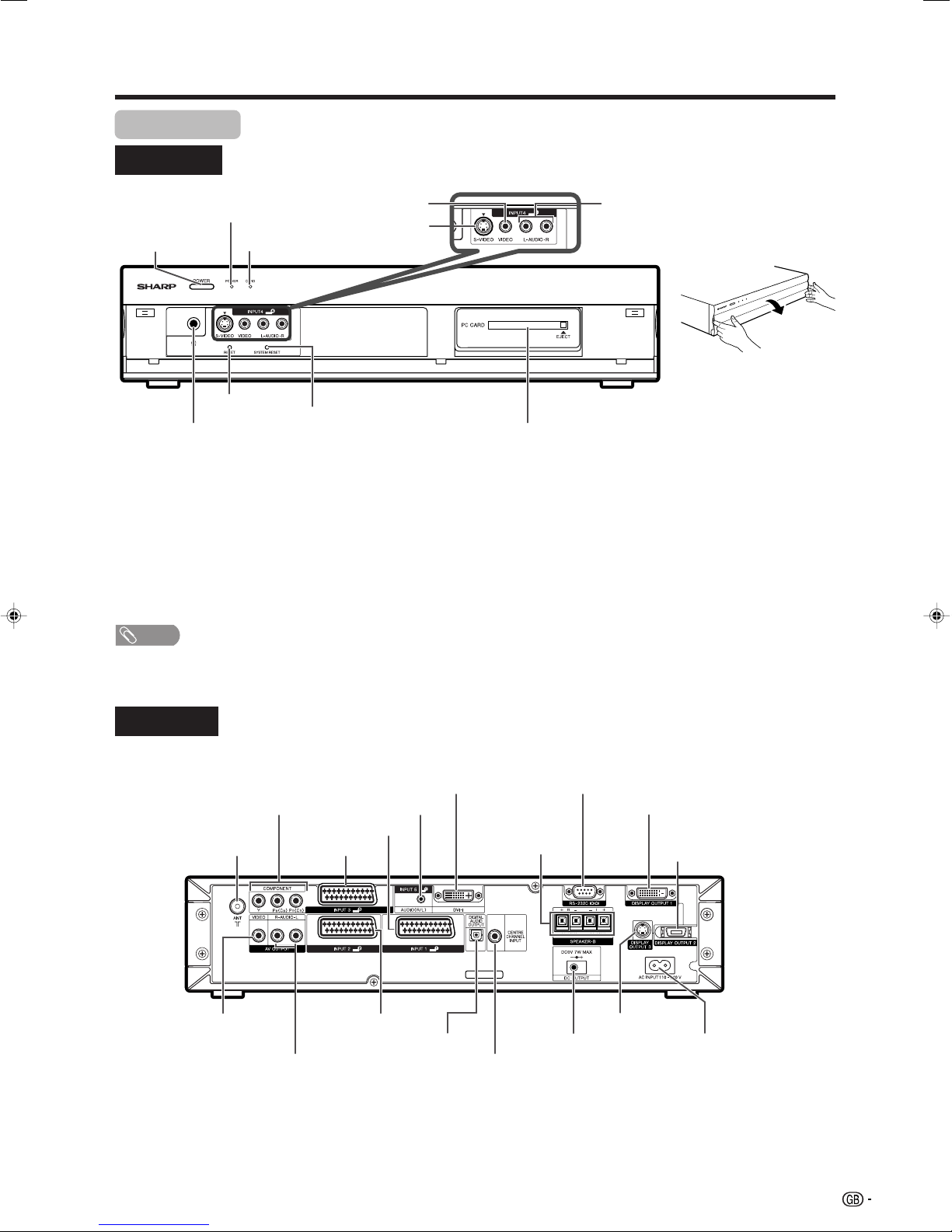
Remote control unit
1 POWER (STANDBY/ON)
To switch the power on and off. (See page 17.)
2 OPC
To switch the Optical Picture Control on and off. (See page 28.)
3 P&P
Set the dual picture mode. Press P&P again to return to normal view.
(See page 58.)
SELECT
To select either screen to be active in Dual screen mode.
4 FREEZE
TV/External input mode: Change the still image mode. (See pages
37 and 58.)
TELETEXT mode: Freeze a multi-page on screen while other pages
are automatically updated. Press FREEZE again to return to the
normal image. (See page 60.)
5 WIDE
TV/External input mode: Change the wide image mode. (See pages
52 and 53.)
TELETEXT mode: Set the area of magnification. (full/upper half/lower
half) (See page 60.)
6 CARD
Switch to the card mode.
Card mode: Press to turn the Card Control Panel on and off. (See
page 36.)
E REC/REC STOP
Still image: Press to capture a still image to a card after freezing the
image from TV or external equipment. (See page 37.)
Motion picture: Press to start/stop recording a motion picture to a card
from TV or external equipment. (See page 40.)
70 – 9
TV/External input mode: Set the channel. (See page 18.)
TELETEXT mode: Set the page. (See page 60.)
8 A (Flashback)
Press to return to the previous image in normal viewing mode. (See
page 18.)
9 [ (SUBTITLE for TELETEXT)
TV/External input mode: To turn the subtitles on and off. (See page
61.)
10 k (Reveal hidden for TELETEXT)
TELETEXT mode: Display hidden characters. (See page 60.)
11 MPX
Select the sound multiplex mode. (See page 19.)
12 VOLk/VOLl
Set the volume. (See page 20.)
13 e (MUTE)
Mute the sound. (See page 20.)
14 EXIT
Turn off the On Screen Display.
15 SLEEP
Set the Sleep timer. (See page 55.)
16 DISPLAY
Display the programme information.
17 AV MODE
Select a video setting: AV MODE (STANDARD, MOVIE, GAME, USER,
DYNAMIC), PC MODE (STANDARD, USER) (See page 51.)
18 3D–Y/C
To switch the 3D–Y/C function on and off. (See page 31.)
19 o (Digit for channel select)
Change the digits of the selected TV channel. (See page 18.)
20 m (TELETEXT)
Select the TELETEXT mode. (all TV image, all TEXT image, TV/TEXT
image) (See pages 60 and 61.)
21 l (TOP Overview for TELETEXT)
TELETEXT mode: Display an index page for CEEFAX/FLOF
information. TOP Overview for TOP programme. (See page 61.)
22 CHr/CHs
TV input mode: Select the channel. (See page 18.)
TELETEXT mode: Select the page. (See page 60.)
23 TV/VIDEO (INPUT SOURCE)
Select an input source. (TV, INPUT 1, INPUT 2, INPUT 3, INPUT 4,
INPUT 5, CARD) (See pages 43, 49, 50 and 58.)
24 MENU
Display the menu screen. (See page 21.)
25 a/b/c/d (Cursor)
Select a desired item on the setting screen. (See page 21.)
ENTER
Execute a command.
26 RETURN
MENU mode: Return to the previous menu screen. (See page 21.)
27 Colour (RED/GREEN/YELLOW/BLUE)
TELETEXT mode: Select a page. (See page 60.)
12
15
3
4
5
6
16
17
18
7
8
9
10
11
12
13
19
20
21
22
23
24
25
14 26
27
NOTE
• When using the remote control unit, point it at the Display.
16
Page 18
Watching TV
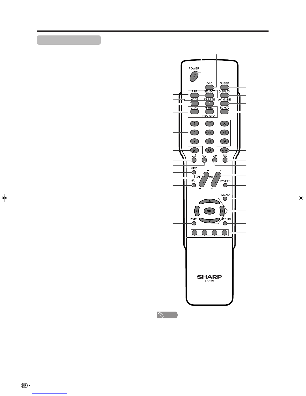
Display
AVC System
POWER button
POWER indicator
POWER
button
POWER
indicator
Turning on the power
Before turning on the power make sure you have completed
required connections. (See pages 7 and 13.)
1
2
Press POWER on the Display.
• POWER indicator (Green): The System is on. (After a
few seconds, programme information appears with
sound.)
• POWER indicator (Red): The System is in standby. (Go
to step 2.)
Use any of the methods below to power on. Powering
on changes the indicator from red to green.
• Press POWER on the AVC System.
• Press POWER on the remote control.
Turning off the power
Press POWER on the remote control unit or POWER on the
Display.
• The System enters standby mode and the image on the screen
disappears.
• Both POWER indicators change from green to red.
Press POWER on the Display.
• The POWER indicator on the Display turns off.
• When the System is turned off by POWER on the Display, you
cannot turn on the power by pressing POWER on the remote
control.
POWER indicator
Off
Red
Green
NOTE
• Check if the system cable is connected properly when display
indicator flashes red.
• If you are not going to use this System for a long period of time, be
sure to remove the AC cords from the power outlet.
• Minor power is cosumed when the unit is in standby mode.
Power off
The System is in standby mode.
The System is on.
17
Page 19
Watching TV
Simple button operations for
changing channels
You can change channels in several ways.
Using CHr/son the remote control unit
• Press CHr to increase the channel number.
• Press CHs
NOTE
• CHr/s on the Display operates the same as CHr/
son the remote control unit.
to decrease the channel number.
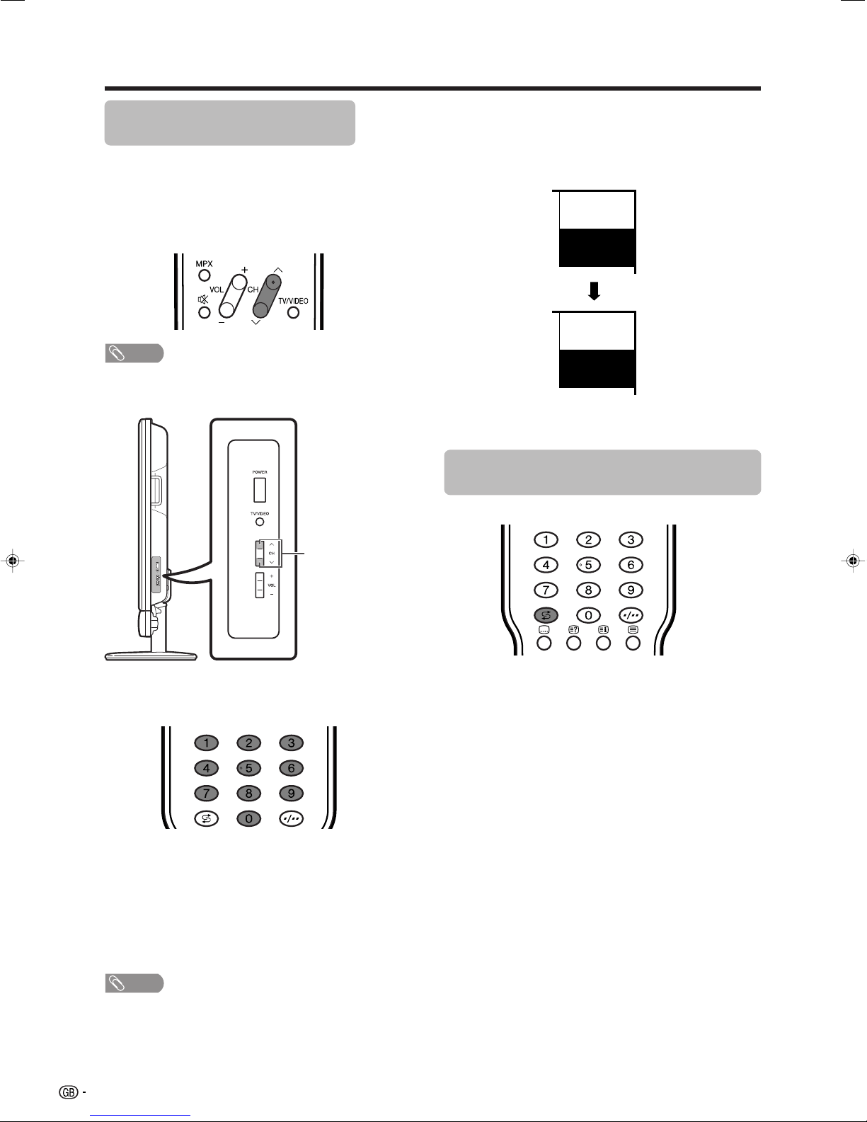
Channel display
Channel display changes approximately after 3
seconds as shown below.
SAT.1
12
PAL
B/G
(Example)
SAT.1
12
MONO
Using Flashback (A) on the remote
control unit
CHr/s
Using 0 – 9 on the remote control unit
Select the channels directly by pressing buttons 0 to
9.
a
To select a 1-digit channel (e.g. channel 2):
• Press 2. If “2” is indicated and the picture does not
change immediately, press o to switch over to the
1-digit select mode and press 2 again.
To select a 2-digit channel (e.g. channel 12):
• Press o to set the 2-digit select mode. Press 1,
followed by 2.
Press A to switch the currently tuned channel to the
previously tuned channel.
Press A again to switch back to the currently tuned
channel.
Press A to toggle between the currently selected input
source and the previously selected one.
Press A to return to the previous page in TELETEXT
mode.
NOTE
• Complete this procedure within 3 seconds, otherwise the
selection will not be made on the 2-digit channel mode.
When viewing Teletext information
View a page directly which is 3-digit page number from
100 to 899 by pressing buttons 0 to 9.
18
Page 20
Watching TV
Using MPX on the remote control
unit
In the NICAM TV broadcasts
When receiving a stereo signal
Each time you press MPX, the mode switches between
NICAM STEREO and MONO.
Stereo mode
BBC2
99
NICAM
STEREO
BBC2
99
MONO
In the TV mode of A2 TV broadcasts
When receiving a stereo signal
Each time you press MPX, the mode switches between
STEREO and MONO.
Stereo mode
BBC2
99
STEREO
BBC2
99
MONO
When receiving a bilingual signal
Each time you press MPX, the mode switches among
CH A, CH B and CH AB.
Bilingual mode
BBC2
99
CH A
BBC2
99
When receiving a bilingual signal
Each time you press MPX, the mode switches among
NICAM CH A, NICAM CH B, NICAM CH AB and
MONO.
Bilingual mode
BBC2
99
NICAM
CH A
BBC2
99
NICAM
CH B
BBC2
99
NICAM
CH AB
BBC2
99
MONO
When receiving a monaural signal
Each time you press MPX, the mode switches between
NICAM MONO and MONO.
Monaural mode
BBC2
99
NICAM
MONO
CH B
BBC2
99
CH AB
When receiving a monaural signal
When you press MPX, “MONO” displays.
Monaural mode
BBC2
99
MONO
NOTE
• When no signal is input, the sound mode will display
“MONO”.
• “BBC2” and “99” are tentative network name and channel.
BBC2
99
MONO
19
Page 21
Watching TV
Simple button operation for changing
volume/sound
Changing the volume
You can change the volume on the Display or on the
remote control unit.
kk
k/
kk
ll
l
ll
VOL
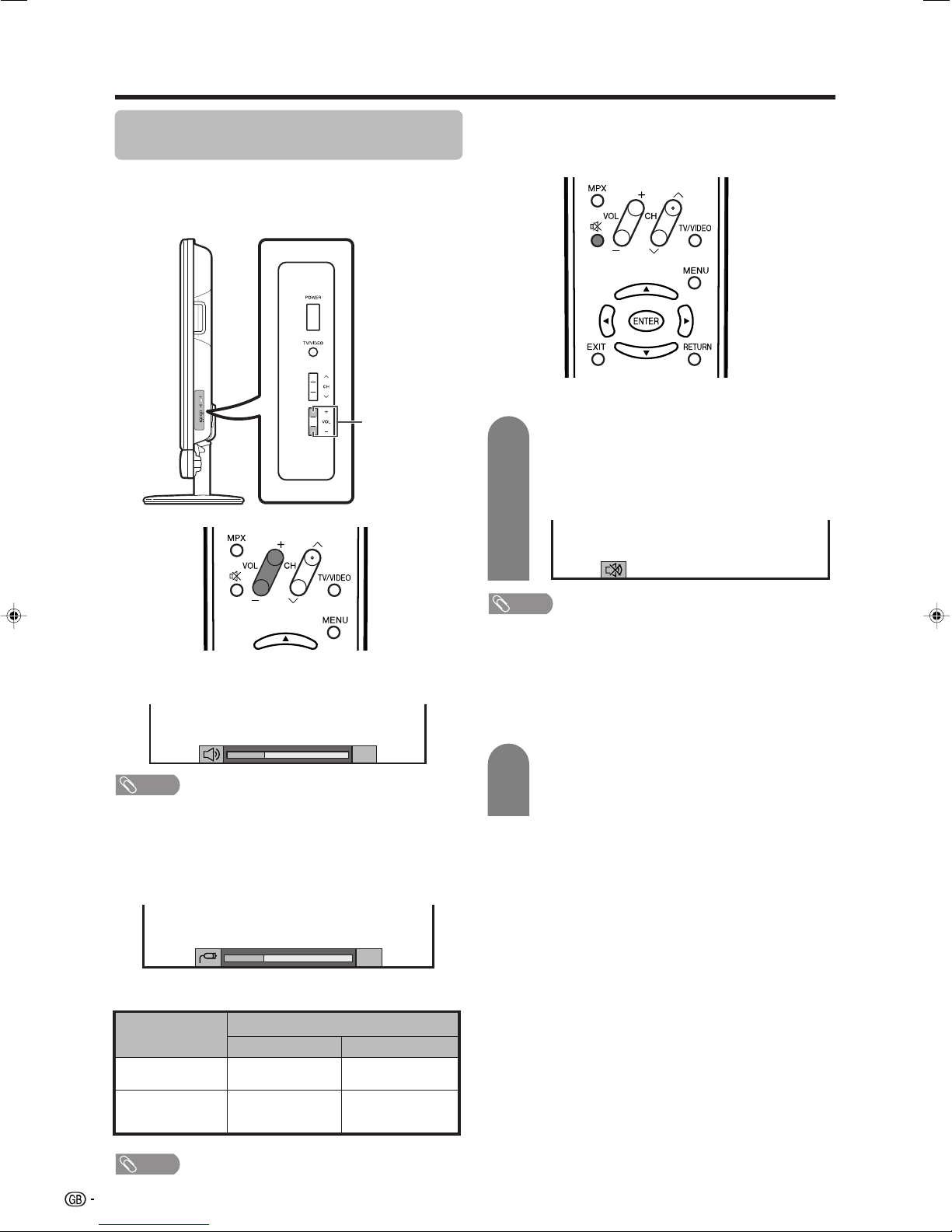
Using e (Mute) on the remote control unit
e mutes the current sound output.
1
Press e.
• The sound is silenced.
•“M” has been displayed on the screen for 30
minutes.
Mute
• To increase the volume, press VOL
• To decrease the volume, press VOL
kk
k.
kk
ll
l.
ll
20
NOTE
• “TV”, “INPUT1”, “INPUT2”, “INPUT3”, “INPUT4”, “INPUT5”
and “CARD” modes can each store volume adjustment
values separately.
When “Audio Out” is set to “Variable”, the indicator on
the screen changes as shown below.
20
Audio status
Output device
Audio out
VariableFixed
NOTE
• Within 30 minutes after pressing e, press one of the
buttons below to cancel the mute.
—VOLk/VO Ll
—e
• Mute will be cancelled after 30 minutes. However, the
TV will not suddenly output loud sound as the volume
level will be set to 0 automatically. Increase the volume
level by pressing VOLk.
2
Press e again within 30 minutes to cancel
the mute.
• Before 30 minutes, the volume level returns to
the previous setting.
Speaker
AV OUTPUT
NOTE
• See page 55 for details on the audio out function.
20
Variable sound
Constant as
specified
Mute
Variable sound
Page 22
Basic adjustment settings
Menu operation buttons
Use the following buttons on the remote control to
operate the menu.
On-Screen Display
Example
...
[
Option
MENU
Option
Audio Only
3D-NR
Mosquito Noise Reduction [Off]
Input Select
Audio Out
Quick Shoot
Colour System
Centre Channel Input
Quick Shoot
[COMPONENT]
1 Item displayed in yellow
• This indicates the item currently selected.
• Press ENTER to go to the adjustment screen
for this item.
2 Item in brackets
• This indicates the current setting for the item.
3 Item displayed in white
• This indicates an item can be selected.
[Off]
[Fixed]
[On]
[On]
]
1
2
3
4
MENU: Press to open or close the menu
screen.
a/b/c/d: Press to select a desired item on the
screen or adjust a selected item.
ENTER: Press to go to the next step or
complete the setting.
RETURN: Press to return to the previous step.
CARD: Press to open or close the Card mode
screen.
ENTER
: Select : Enter
RETURN
: Back
MENU
: End
4 Item displayed in grey
• This indicates that the item cannot be
selected.
*There are various reasons why items cannot
be selected, but the main reasons are as
follows:
1. Nothing is connected to the selected
input terminal.
2. The function is not compatible with the
current input signal.
NOTE
• Menu options vary according to the selected input mode,
but the operating procedures are the same.
• The screens in the operation manual are for explanation
purposes (some are enlarged, others cropped) and may
vary slightly from the actual screens.
The bar above is an operational guide for
the remote control. The bar will change in
accordance with each menu setting
screen.
21
Page 23
Basic adjustment settings
TV/AV input mode menu items
List of TV/AV menu items to help you with
operations
OPC ........................................................ Page 28
Backlight ................................................ Page 29
Contrast ................................................. Page 29
Brightness ............................................. Page 29
Colour .................................................... Page 29
Tint ......................................................... Page 29
Sharpness .............................................Page 29
Advanced
C.M.S. .......................................... Page 30
Colour Temp. .............................. Page 30
Sharpness Enhancement ......... Page 30
Automatic Contrast ...................Page 30
I/P Setting ...................................Page 31
Film Mode ................................... Page 31
3D-Y/C ......................................... Page 31
Monochrome .............................. Page 31
Treble ..................................................... Page 32
Bass ....................................................... Page 32
Balance .................................................. Page 32
Dolby Virtual .......................................... Page 32
Picture
Audio
PC input mode menu items
List of PC menu items to help you with operations
Picture
OPC ........................................................ Page 28
Backlight ................................................ Page 29
Contrast ................................................. Page 29
Brightness ............................................. Page 29
Red ......................................................... Page 29
Green ...................................................... Page 29
Blue ........................................................ Page 29
Advanced
C.M.S. .......................................... Page 30
Sharpness Enhancement ......... Page 30
Audio
Treble ..................................................... Page 32
Bass ....................................................... Page 32
Balance .................................................. Page 32
Dolby Virtual .......................................... Page 32
Power Control
No Signal Off ......................................... Page 33
No Operation Off ................................... Page 33
Setup
Auto Installation.................................... Page 23
Programme Setup ......................... Pages 23-27
Child Lock.............................................. Page 56
Input Label ............................................. Page 50
Speaker Setup ....................................... Page 47
Position .................................................. Page 48
WSS ........................................................Page 51
4:3 Mode ................................................ Page 51
Rotate ..................................................... Page 54
Language ............................................... Page 28
Text Language....................................... Page 59
Option
Audio Only ............................................. Page 48
3D-NR ..................................................... Page 54
Mosquito Noise Reduction .................. Page 55
Input Select ........................................... Page 49
Audio Out............................................... Page 55
Quick Shoot ........................................... Page 54
Colour System ...................................... Page 50
Centre Channel Input ........................... Page 57
Power Control
Power Management .............................. Page 33
Setup
Input Label ............................................. Page 50
Speaker Setup ....................................... Page 47
Input Signal ........................................... Page 54
Auto Sync. ............................................. Page 48
Fine Sync. .............................................. Page 49
Rotate ..................................................... Page 54
Language ............................................... Page 28
Option
Audio Only ............................................. Page 48
Input Select ........................................... Page 49
Audio Out............................................... Page 55
Quick Shoot ........................................... Page 54
Centre Channel Input ........................... Page 57
22
Page 24

Basic adjustment settings
Auto installation
You can run auto installation again, even after setting
up the preset channels.
1
2
3
4
Press MENU and the MENU screen displays.
Press c/d to select “Setup”.
Press a/b to select “Auto Installation”, and
then press ENTER.
...
[
Setup
MENU
Setup Option
Auto Installation
Programme Setup
Child Lock
Speaker Setup
Position
WSS
4:3 Mode
Rotate
Language
Auto Installation
[Panorama]
[Normal]
[English]
[West Europe]Text Language
]
[On]
If you have already set the password, enter
it here.
• See page 56 for setting password.
––––
Programme setup
You can run the auto search procedure again at any
time by accessing the Setup menu and Programme
Setup. Channels can be tuned automatically or
manually.
Auto search
You can also automatically search by performing the
procedure below. This is the same function as
programme auto search in auto installation.
1
2
3
4
Press MENU and the MENU screen displays.
Press c/d to select “Setup”.
Press a/b to select “Programme Setup”,
and then press ENTER.
If you have already set the password, enter
it here.
• See page 56 for setting password.
...
[
Setup
MENU
Setup Option
Auto Installation
Programme Setup
Child Lock
Speaker Setup
Position
WSS
4:3 Mode
Rotate
Language
Programme Setup
[Panorama]
[Normal]
[English]
[West Europe]Text Language
]
[On]
Press a/b to select “Auto Search”, and then
press ENTER.
5
Press c/d to select “Yes”, and then press
ENTER.
6
Press a/b to select the desired language
listed on the screen, and then press ENTER.
After this setting, auto search starts with the
following order.
1 Programme auto search
2 Auto labelling
3 Auto sorting
You do not need to do anything during the
auto search.
NOTE
• After performing step 6, the menu screen shown in step 3
will reappear. Do not turn off the System before then,
because the System is saving the data found.
5
Press c/d to select “Yes”, and then press
ENTER.
• Auto search starts with the following order.
1 Programme auto search
2 Auto labelling
3 Auto sorting
NOTE
• After performing step 5, the menu screen shown in step 3
will reappear. Do not turn off the System before then,
because the System is saving the data found.
23
Page 25

Basic adjustment settings
Fine
Colour sys.
Sound sys.
Label
Skip
Lock
[179.25]
Search
[AUTO]
[B/G]
[Off]
[SAT.1]
[Off]
Booster [Off]
179.25 MHz
MENU
[
Setup
...
Programme Setup
...
Manual Adjust
]
Fine
Colour sys.
Sound sys.
Label
Skip
Lock
[179.25]
Search
[AUTO]
[B/G]
[Off]
[SAT.1]
[Off]
Booster [Off]
179.25 MHz
NEXT
STORE
CANCEL
Manual setting for each channel
You can set some channel items manually. They are
Search, Fine (TV frequency), Colour sys., Sound sys.,
Label (Network name), Skip, Lock (Child Lock) and
Booster.
1
2
3
4
5
Press MENU and the MENU screen displays.
Press c/d to select “Setup”.
Press a/b to select “Programme Setup”,
and then press ENTER.
If you have already set the password, enter
it here.
• See page 56 for setting password.
Press a/b to select “Manual Adjust”, and
then press ENTER.
Press c/d to select “Yes”, and then press
ENTER.
Programme Setup “Manual Adjust” menu
Search tuning
1
Press a/b/c/d to select the channel you
want to edit, and then press ENTER.
• The selected channel information displays.
2
Press a/b to select “Search”, and then
press ENTER.
3
• Search tuning cannot be used when L’ is selected in Sound
system menu. (See page 25.)
Press a/b to select item and press ENTER.
• NEXT: Search the next channel.
• STORE: Memorise the current display channel.
• CANCEL: Return to the previous screen. (The
search result will not be stored.)
NOTE
01 SAT.1 02 PR07 03 KABEL
Next
You can select one of the following settings.
1 Search (See page 24.)
2 Fine (See page 24.)
3 Colour system (See page 25.)
4 Sound system (See page 25.)
5 Label (See page 25.)
6 Skip (See page 26.)
7 Lock (See page 26.)
8 Booster (See page 26.)
Fine tuning
1
Press a/b/c/d to select the channel you
want to edit, and then press ENTER.
• The selected channel information displays.
2
Press a/b to select “Fine”, and then press
ENTER.
3
Press c/d to adjust the frequency, and then
press ENTER.
• Adjust while checking the background picture
• Instead of the method above, you can also set
a
• 179.25 MHz: Press 1 s 7 s 9 s 2 s 5.
• 49.25 MHz: Press 4 s 9 s 2 s 5 s ENTER.
as a reference.
by directly entering the frequency number of
the channel with 0 – 9.
24
Page 26

Basic adjustment settings
Manual setting for each channel (continued)
Colour system
1
2
3
Sound system (Broadcasting system)
1
Press a/b/c/d to select the channel you
want to edit, and then press ENTER.
• The selected channel information displays.
Press a/b to select “Colour sys.”, and then
press ENTER.
• Receivable colour systems are listed.
Colour system menu
...
[
Setup
MENU
Search
Fine
Colour sys.
Sound sys.
Label
Skip
Lock
Booster [Off]
Programme Setup
[179.25]
[AUTO]
[B/G]
[SAT.1]
[Off]
[Off]
...
Manual Adjust
]
AUTO
PAL
SECAM
NTSC 4.43
PAL-60
Press a/b to select the optimum colour
system, and then press ENTER.
Press a/b/c/d to select the channel you
want to edit, and then press ENTER.
• The selected channel information displays.
Labelling channels
When a TV channel sends its Network Name, the auto
installation detects the information and assigns a name
to it. However, you can change individual channel
names.
1
Press a/b/c/d to select the channel you
want to edit, and then press ENTER.
• The selected channel information displays.
2
Press a/b to select “Label”, and then press
ENTER.
• Alphabets and numbers are listed.
Labelling menu
Search
Fine
Colour sys.
Sound sys.
Label
Skip
Lock
Booster [Off]
3
Press a/b/c/d to select each character
[179.25]
[AUTO]
[B/G]
[SAT.1]
[Off]
[Off]
A
B
C
D
E
F
G
H
I
K
L
M
N
O
P
Q
R
S
U
V
W
X
Y
Z
+
– _
.
0123456789
J
T
CLEAR
BACK
END
of the new name for the channel, and then
press ENTER.
4
Repeat until the name is fully spelt out.
• The name can be 5 characters or less.
2
Press a/b to select “Sound sys.”, and then
press ENTER.
• Receivable sound systems (Broadcasting
systems) are listed.
Sound system menu
Search
Fine
Colour sys.
Sound sys.
Label
Skip
Lock
Booster [Off]
3
Press a/b to select the optimum sound
[179.25]
[AUTO]
[B/G]
[SAT.1]
[Off]
[Off]
B/G
D/K
I
LL
L’
system, and then press ENTER.
NOTE
• Check the colour system (see above) if the sound output
were not correct.
25
Page 27

Basic adjustment settings
Manual setting for each channel (continued)
Skipping channels
Channels with “Skip” set to “On” are passed over when
using CHr/s even if selected while watching the
image from the TV.
1
2
3
Press a/b/c/d to select the channel you
want to edit, and then press ENTER.
• The selected channel information will be
displayed.
Press a/b to select “Skip”, and then press
ENTER.
• Skip menu displays.
Skip menu
...
[
Setup
MENU
Search
Fine
Colour sys.
Sound sys.
Label
Skip
Lock
Booster [Off]
Programme Setup
[179.25]
[AUTO]
[B/G]
[SAT.1]
[Off]
[Off]
...
Manual Adjust
]
Off
On
Press a/b to set “Skip” to “On”, and then
press ENTER.
Setting the child lock
You can block the viewing of any channel.
1
Press a/b/c/d to select the channel you
want to edit, and then press ENTER.
• The selected channel information will be
displayed.
2
Press a/b to select “Lock”, and then press
ENTER.
• Child lock menu will be displayed.
Lock menu
Search
3
Fine
Colour sys.
Sound sys.
Label
Skip
Lock
Booster [Off]
Press a/b to set “Lock” to “On”, and then
press ENTER.
[179.25]
[AUTO]
[B/G]
[SAT.1]
[Off]
[Off]
Off
On
NOTE
• See page 56 for setting password.
• When “Lock” is set to “On” for a channel, “Child lock has
been activated.” is displayed , and the image and sound
of the channel is blocked.
• When pressing ENTER while “Child lock has been
activated.” is displayed, password input menu will be
displayed. Inputting the correct password lifts the child
lock temporarily until the power is turned off.
Setting the booster
Picture quality may improve in regions with weak signal
strength using this function.
1
Press a/b/c/d to select the channel you
want to edit, and then press ENTER.
2
Press a/b to select “Booster”, and then
press ENTER.
• Booster menu displays.
Booster Menu
Search
3
Fine
Colour sys.
Sound sys.
Label
Skip
Lock
Booster [Off]
Press a/b to set “Booster” to “On”, and then
[179.25]
[AUTO]
[B/G]
[SAT.1]
[Off]
[Off]
Off
On
press ENTER.
NOTE
• If signal strength is strong enough for the selected
channel, the effect is negligible and may produce
instability. In such case, select “Off”.
26
Page 28

Basic adjustment settings
Sort
Channel positions can be sorted freely.
1
2
3
4
5
6
7
Press MENU and the MENU screen displays.
Press c/d to select “Setup”.
Press a/b to select “Programme Setup”,
and then press ENTER.
If you have already set the password, enter
it here.
• See page 56 for setting password.
Press a/b to select “Sort”, and then press
ENTER.
Press c/d to select “Yes”, and then press
ENTER.
Press a/b/c/d to select the channel you
want to move, and then press ENTER.
Move it to the desired position by pressing
a/b/c/d, and then press ENTER.
Erase Programme
The individual programme can be erased.
1
2
3
4
5
6
Repeat steps 1 to 3 in Sort.
Press a/b to select “Erase Programme”,
and then press ENTER.
Press c/d to select “Yes”, and then press
ENTER.
Press a/b/c/d to select the channel you
want to erase, and then press ENTER.
• A message screen pops up.
Press c/d to select “Yes”, and then
press ENTER to erase the selected
programme. All the subsequent
programmes move up.
Repeat the steps 4 and 5 until all desired
channels are erased.
Erase programme menus
01 SAT.1
8
Repeat the steps 6 and 7 until all desired
channels are sorted.
Sort menus
01 SAT.1
0106SAT.1 KABEL
02 03 04 05
Next
01 SAT.1 02 KABEL
01 SAT.1 KABEL02
Next
01 KABEL
01 KABEL SAT.102
SAT.1
01
06 07 08 09 10
11 12 13 14 15
16 17 18 19 20
01 SAT.1 03 KABELPro702
06 07 08 09 10
11 12 13 14 15
16 17 18 19 20
01 SAT.1 02 KABEL
06 07 08 09 10
11 12 13 14 15
16 17 18 19 20
Pro702 KABEL03 04 05
Next
02 Pro7
04 05
Next
02 KABEL
03 04 05
Next
Next
27
Page 29

Basic adjustment settings
Language setting for on-screen
display
You can also select a language from setup menu.
Select from among 3 languages: English, Chinese and
Arabic.
1
2
3
4
Press MENU and the MENU screen displays.
Press c/d to select “Setup”.
Press a/b to select “Language”, and then
press ENTER.
Press a/b to select the desired language
listed on the screen, and then press ENTER.
OPC (Optical Picture Control) setting
You can set the System to automatically adjust the
screen to suitable backlight brightness according to
the lighting conditions.
Using OPC on the remote control unit
Press OPC to switch the Optical Picture Control on
and off.
Selected item
Off
On
The brightness is fixed at the value set in
“Backlight” (see page 29).
Automatically adjusts
Description
Using OPC on the menu screen
1
2
3
4
• When set to “On”, the System senses the surrounding light
and automatically adjusts the backlight brightness. Make
sure no object obstructs the OPC sensor, which could
affect its ability to sense surrounding light.
Press MENU and the MENU screen displays.
Press c/d to select “Picture”.
Press a/b to select “OPC”.
Press c/d to select “On”.
NOTE
28
Page 30

Basic adjustment settings
Picture adjustments
You can adjust the picture to your preference.
Follow the steps to adjust the picture.
1
Press MENU and the MENU screen displays.
[
]
MENU
Picture
Picture Audio
USER [TV]
OPC
Backlight [+16] –16
Contrast
Brightness
Colour
Tint
Sharpness
Advanced
Reset
[+30]
[0]
[0]
[0]
[0]
0
–30
–30
–30
–10
Off On
+16
+40
+30
+30
+30
+10
2
3
Press c/d to select “Picture”.
Press a/b to select a specific adjustment
item.
4
Press c/d to adjust the item to your desired
position.
NOTE
• For resetting all adjustment items to factory preset values,
press a/b to select “Reset”, press ENTER, press c/d
to select “Yes”, and then press ENTER.
Adjustments items for PC sourceAdjustments items for AV source
[
]
MENU
Picture
Picture Audio
USER [PC]
OPC
Backlight [+16] –16
Contrast
Brightness
Red
Green
Blue
Advanced
Reset
[+30]
[0]0–30
[0]
–30
[0]
–30
[0]
–30
Off On
+16
+40
+30
+30
+30
+30
Selected item
Backlight
Contrast
Brightness
Colour
Tint
Sharpness
cbutton
The screen dims
For less contrast
For less brightness
For less colour
intensity
Skin tones become
purplish
For less sharpness
NOTE
• Select “Advanced” and then press ENTER to set “C.M.SHue”, “C.M.S-Saturation”, “C.M.S-Value”, “Colour Temp.”,
“Sharpness Enhancement”, “Automatic Contrast”, “I/P
Setting”, “Film Mode”, “3D-Y/C” or “Monochrome”. See
pages 30 and 31.
dbutton
The screen brightens
For more contrast
For more brightness
For more colour
intensity
Skin tones become
greenish
For more sharpness
Selected item
Backlight
Contrast
Brightness
Red
Green
Blue
cbutton
The screen dims
For less contrast
For less brightness
For weaker red
For weaker green
For weaker blue
dbutton
The screen brightens
For more contrast
For more brightness
For stronger red
For stronger green
For stronger blue
NOTE
• Select “Advanced” and then press ENTER to set “C.M.SHue”, “C.M.S-Saturation”, “C.M.S-Value” or “Sharpness
Enhancement”.
29
Page 31

Basic adjustment settings
Advanced
Advanced setting enables you to set the picture
adjustment in more detail. There are eight options
you can choose from.
C.M.S. (Colour Management System)
Colour tone is managed using the six-colour
adjustment setting.
1
2
3
4
5
Press MENU and the MENU screen displays.
Press c/d to select “Picture”.
Press a/b to select “Advanced”, and then
press ENTER.
Press a/b to select “C.M.S.-Hue”, and then
press ENTER.
Press a/b to select a specific adjustment
item.
C. M. S-Hue
C. M. S-Saturation
C. M. S-Value
Changing reds
closer to
magenta or yellow.
Reset
• You can select “C.M.S-Saturation” or “C.M.SValue” here instead of selecting “C.M.S-Hue”.
R
Y
G
C
B
M
–30
[ 0]
[ 0]
–30
[ 0]
–30
[ 0]
–30
[ 0] –30
[ 0] –30
+30
+30
+30
+30
+30
+30
Colour temperature
Adjusts the colour temperature to give the best white
image.
1
Repeat steps 1 to 3 in C.M.S. (Colour
Management System).
2
Press a/b to select “Colour Temp.”, and
then press ENTER.
3
Press a/b to select the desired level, and
then press ENTER.
Selected item
High
Mid-High
Middle
Mid-Low
Low
Description
White with bluish tone
White with reddish tone
Sharpness Enhancement
Provides sharper images with more depth by adjusting
background sharpness.
1
2
3
Repeat steps 1 to 3 in C.M.S. (Colour
Management System).
Press a/ b to select “Sharpness
Enhancement”, and then press ENTER.
Press c/d to select the desired level, and
then press ENTER.
• The higher the number of the level, the more
sharpness and depth you will get in images.
6
Press c/d to adjust the item to your desired
position.
NOTE
• For resetting all adjustment items to factory preset values,
press a/b to select “Reset”, press ENTER, press c/d
to select “Yes”, and then press ENTER.
Selected item
C.M.S-Hue
C.M.SSaturation
C.M.S-Value
30
This is a standard to adjust the colour
either more reddish or more bluish in tone.
Increases or decreases the saturation of a
selected colour
A higher value makes the image brighter.
A lower value makes the image darker.
Description
Automatic Contrast
Adjusts black level and white level in images
automatically as appropriate to a particular scene.
1
2
3
Selected item
On
Off
Repeat steps 1 to 3 in C.M.S. (Colour
Management System).
Press a/b to select “Automatic Contrast”,
and then press ENTER.
Press c/d to select “On” or “Off”, and then
press ENTER.
Description
Automatically adjusts
For normal images
Page 32

Basic adjustment settings
I/P setting
Adjusting the image and input signal can give you a
more beautiful picture.
1
2
3
4
5
• The I/P Setting is set to Slow when Film Mode is “On”.
Press MENU and the MENU screen displays.
Press c/d to select “Picture”.
Press a/b to select “Advanced”, and then
press ENTER.
Press a/b to select “I/P Setting”, and then
press ENTER.
• Some items may be greyed out. They are not
selectable.
Press c/d to select “Fast” or “Slow”, and
then press ENTER.
NOTE
Film mode
Automatically detects a film-based source (originally
encoded at 24/25 frames/second, depending on the
vertical frequency), analyses it then recreates each
still film frame for high-definition picture quality.
1
2
Repeat steps 1 to 3 in I/P setting.
Press a/b to select “Film Mode”, and then
press ENTER.
• Some items may be greyed out. They are not
selectable.
3D-Y/C
Provides high quality images with minimal dot crawl
and cross colour noise.
Using 3D-Y/C on the remote control unit
Press 3D-Y/C to switch the 3D-Y/C function on and
off.
NOTE
• “3D-Y/C” is set to “On” when the System is turned back
on.
• 3D-Y/C may not operate depending on the input signal
type or noisy input signal.
• 3D-Y/C is automatically set to “On” when you change
channels or input sources.
1
2
3
Selected item
Standard
Fast
Slow
• “3D-Y/C” is not selectable depending on the input signal
type.
Repeat steps 1 to 3 in I/P setting.
Press a/b to select “3D-Y/C”, and then
press ENTER.
Press a/b to select the desired level, and
then press ENTER.
Description
Normal adjustment
For movie image
For still image
NOTE
3
Selected item
Off
On
Press c/d to select “On”, and then press
ENTER.
Description
Normal viewing mode
Detects, analyses, converts film source
Monochrome
For viewing a video in monochrome.
1
2
3
Selected item
Off
On
Repeat steps 1 to 3 in I/P setting.
Press a/b to select “Monochrome”, and
then press ENTER.
Press c/d to select “On”, and then press
ENTER.
Description
Normal colour
For viewing in monochrome
31
Page 33

Basic adjustment settings
Audio adjustment
You can adjust the sound quality to your preference
with the following settings.
1
2
3
4
Selected item
Press MENU and the MENU screen displays.
Press c/d to select “Audio”.
[
]
MENU
Audio
Audio Power Control
USER [TV]
Treble
Bass
Balance
Dolby Virtual
Reset
[0] –15
[0]
–15
[0]
L
Press a/b to select a specific adjustment
item.
Press c/d to adjust the item to your desired
position.
cbutton
+15
+15
R
[Off]
dbutton
Dolby Virtual
When you set Dolby Virtual to On, you can enjoy virtual
surround sound, the same as if you were in a movie
theatre.
1
2
3
Press MENU and the MENU screen displays.
Press c/d to select “Audio”.
Press a/b to select “Dolby Virtual”, and
then press ENTER.
...
[
Audio
MENU
Audio Power Control
Dolby Virtual
]
USER [TV]
Treble
Bass
Balance
Dolby Virtual
Reset
4
Press c/d to select “On”, and then press
[0] –15
[0]
–15
[0]
L
ENTER.
+15
+15
R
[Off]
Treble
Bass
Balance
For weaker treble
For weaker bass
Decrease audio from
the right speaker
For stronger treble
For stronger bass
Decrease audio from
the left speaker
NOTE
• For resetting all adjustment items to factory preset values,
press a/b to select “Reset”, press ENTER, press c/d
to select “Yes”, and then press ENTER.
• Audio menu items are greyed out when Audio output is
variable or when headphones are in use.
• Balance is greyed out when Dolby Virtual is set to “On”.
NOTE
• Audio menu items are greyed out when Audio output is
variable or when headphones are in use.
• External Audio Bypass is greyed out when Dolby Virtual
is set to “On”.
• Balance is greyed out when Dolby Virtual is set to “On”.
• For some discs, setup may be required on your DVD. In
this case, refer to the operation manual of your DVD player.
• You may not get the Dolby Virtual Surround effect if you
adjust “Treble” or “Bass” setting.
32
Page 34

Basic adjustment settings
Power control
Power control setting allows you to save energy.
Power control for AV source
No Signal off
When set to “Enable”, the power will automatically shut
down if no signal inputs for 15 minutes.
1
2
3
4
• “Disable” is factory preset value.
• When a TV programme finishes, and the AVC System
receives signal input, this function may not operate.
Press MENU and the MENU screen displays.
Press c/d to select “Power control”.
• Power control menu displays.
Press a/b to select “No Signal Off”, and
then press ENTER.
Press c/d to select “Enable”, and then
press ENTER
• Five minutes before the power shuts down,
remaining time displays every minute.
NOTE
Power control for PC source
Power management
When set, the power will automatically shut down if no
signal is input for a certain time.
1
2
3
4
Press MENU and the MENU screen displays.
Press c/d to select “Power control”.
• Power control menu displays.
Press a/b to select “Power Management”,
and then press ENTER.
Press a/b to select “Mode1” or “Mode2”,
and then press ENTER.
Off
Mode1
Mode2
No Operation off
When set to “Enable”, the power will automatically shut
down if there is no operation for 3 hours.
1
2
3
Press MENU and the MENU screen displays.
Press c/d to select “Power control”.
• Power control menu displays.
Press a/b to select “No Operation Off”, and
then press ENTER.
4
Press c/d to select “Enable”, and then
press ENTER.
• Five minutes before the power shuts down,
remaining time displays every minute.
NOTE
• “Disable” is factory preset value.
Selected item
Off
Mode1
Mode2
NOTE
• If you turn off the power by disconnecting AC cord when
setting “Mode2” in power management, the TV may not
function properly after turning the power on again. In such
case, press POWER on the remote control unit.
• Pressing POWER on the display will have the same result.
• When selecting “PC digital” in Input Select and setting
“Mode 2” in power management, depending on the model
of the computer, the power may not turn back on
automatically even if the signal inputs again.
• No power management
• Factory preset value.
• If no signal inputs for 8 minutes, the power
shuts down.
• Even if you start using the PC and the signal
inputs again, the System stays off.
• The System turns on again by pressing
POWER. (See page 17.)
• If no signal inputs for 8 seconds, the power
shuts down.
• When you start using the PC and the signal
inputs again, the System turns on.
• The System turns on again by pressing
POWER. (See page 17.)
Description
33
Page 35

Using memory card
Important notes on using memory cards
• SHARP cannot be held responsible for misuse of the LCD TV set, any troubles during use, or other problems, or any
damages arising out of the use of the LCD TV set, except for those cases for which SHARP is liable by law.
• If you or other people misuse the LCD TV set, or the LCD TV set is affected by static electricity or electrical noise, the
recorded data may be in danger of being changed or lost.
• If you are making an important recording, run a test in advance to ensure that the recording would be performed correctly
in terms of picture or sound quality.
• SHARP cannot be held responsible nor make any compensations even if pictures or sound cannot be recorded correctly
because of any troubles when using the LCD TV set.
Copyright
Note:
Audio-visual material may consist of copyrighted works which must not be recorded without the authority of the
owner of the copyright.
Please refer to relevant law in your country.
Duplicating images and music by copying and/or editing from videocassettes and/or TV programmes that are
subject to copyrights is only permitted when the edited or copied versions are used for personal pleasure. With
the exception of cases when the user personally is the owner of the copyrights of the object in question or when
specific and written permission has been obtained from the owner(s) of the object in question, the user is not
permitted to make copies and/or duplications and/or edited versions as this constitutes a violation of the copyright laws, possible exposing the user to demands for compensation for damages. Therefore, be sure to strictly
observe the existing copyright laws.
In addition when using image data that includes third parties, since the use of such images without prior permission may constitute an intrusion on the privacy of third parties, be sure to refrain from such usage.
The recording formats
Still picture
Motion picture
* Motion picture files and still image files recorded, stored or edited with other devices may not play back correctly.
Recording/Playback file format
Size of a captured still picture
Recording file format
Size of a recorded motion
picture/number of frames
Playback file format
JPEG (DCF compliant)
640g480 dots
SP/LP... ASF (Motion Picture: MPEG-4 compliant, Sound: WMA-compliant)
EP........ ASF (Motion Picture: MPEG-4 compliant, Sound: G.726-compliant)
SP ... Size: 320g240 dots, Frame: approx. 25 frames/sec (50 Hz)
LP ... Size: 320g240 dots, Frame: approx. 25 frames/sec (50 Hz)
EP ... Size: 320g240 dots, Frame: approx. 12.5 frames/sec (50 Hz)
ASF (Motion Picture: MPEG-4 compliant, Sound: WMA-compliant)
ASF (Motion Picture: MPEG-4 compliant, Sound: G.726-compliant)
Approximate number of recordable pictures/time
Still pictures
Picture size
Recordable Pictures
* Recordable numbers may vary depending on the receiving condition of the LCD TV set and/or content of images.
640g480
Approx. 300 pictures
Memory card capacity
32MB
Approx. 1000 pictures
128MB
Motion pictures
Memory card capacity
256MB
Approx. 1h
5GB
Approx. 4h
Approx. 10h
Approx. 25h
Recordable time
Picture size
320g240
320g240
320g240
Recording mode
SP
LP
EP
Approx. 10 min.
Approx. 30 min.
• Recordable time may vary depending on receiving condition of the LCD TV set or content of images.
• The maximum amount of data you can record on a memory card is 1,000 pictures in total including still and motion
pictures.
• Files in excess of 4GB and files exceeding 12 hours of recording time cannot be recorded and/or played back.
34
Page 36

Using memory card
You can use memory cards (commercially available)
for recording and playing back pictures.
• Please use an appropriate PC card adaptor
(commercially available) for each memory card.
• Following memory cards are available. (Note that
names for memory cards vary depending on
manufacturers.)
Memory card name
SD Memory Card
mini SD™ Card
CompactFlash
MultiMediaCard
SmartMedia
Memory Stick
Memory Stick PRO
Microdrive
xD Picture Card
PC Card Hard Disk
Storage capacity
512 MB or less
32 MB or less
2 GB or less
128 MB or less
128 MB or less
128 MB or less
1 GB or less
2 GB or less
128 MB or less
5 GB or less
* Each memory card name is a trademark.
* The capacity of memory card is approximate. The
capacity varies depending on the manufacturer.
• To read picture files recorded with digital cameras,
use the PC card adaptor recommended by the
corresponding manufacturer. (The names for PC
card adaptors vary depending on manufacturers.)
• For directions for use of digital cameras or PC card
adaptors, please refer to the operation manual
provided for each product.
• Depending on the card or adaptor used, normal
operation may not be possible.
You can playback DCF compliant JPEG pictures
captured with other devices in the card playback
mode.
• DCF (Design rule for Camera File system) is a
standard of the Japan Electronics and Information
Technology Industries Association (JEITA). This
standard specifies the image file format used for
images shot with a digital camera.
• Some motion pictures recorded with other devices
may not be played back correctly.
Commercially available memory cards
SD Memory
Card
mini SD™ Card
MultiMediaCard
CompactFlash
SmartMedia
• Please use an appropriate PC card adaptor
(commercially available) for each memory card.
Preparing a memory card
Insert a memory card (commercially available) into a PC
card adaptor (commercially available).
Example:
Inserting the SD memory card into a PC card adaptor.
PC card adaptor
Memory Stick
Memory Stick
PRO
PC Card
Hard Disk
xD Picture Card
Microdrive
Notes on using memory cards and PC card adaptor
Please note the following when using memory cards and PC card adaptors to avoid corruption of data or
malfunction of the LCD TV set.
• If you use memory cards other than those shown above, recording or playing back pictures are not
guaranteed.
• Some PC card adaptors have restrictions of memory card capacity. Refer to the relevant operation manual
for such restrictions.
• Some pictures which have been created, modified, or copied on your PC may not be played back.
• Please be sure to turn off the LCD TV set when you insert or remove a PC card adaptor.
• Do not bend, drop or apply a shock to memory cards or PC card adaptors.
• Keep memory cards or PC card adaptors away from heat, water or direct sunlight.
• Do not dismantle or modify memory cards or PC card adaptors.
• Refer to the appropriate operation manuals for details on using or keeping memory cards or PC card
adaptors.
• Do not turn the LCD TV set off while a memory card is in operation (e.g. playing back, recording or
displaying a slideshow).
• The recorded data may be erased or changed due to incorrect operation, the influence of static electricity
and electrical noise, therefore be sure to back-up the data regularly.
• Be sure to back-up important files using other media such as a PC.
35
Page 37

Using memory card
Card Setup mode menu items
Press CARD first to access following items.
Still Setup Slide Show Setup
Interval
1-10/15/20/25/30/
45/60 s.
15/30/60 Min.
Card
Video Setup
Format
Slide show operation panel Motion picture operation panel
CARD - STILL
SLIDE SHOW
1 Rotate the image
2 Pause
3 Go to previous image
4 Start slide show
5 Stop slide show
6 Go to next image
My Programme
Audio Select
Edit
Rec. Mode
Pre-recording
Repeat
Edit
Yes/No
1
2
0001/0045 ORDER:NORMAL REPEAT:OFF
PREV.
NEXT
345 6
Order
Normal/Random/
My Programme
Repeat
On/Off
Setup/Erase
Off/TV/INPUT1-INPUT5
Protect/Delete File/ Delete All
SP/LP/EP
On/Off
Off/File/All
Protect/Delete File/Delete All
12345
CARD - VIDEO
PLAY
MODE : SP
00:15:25
PLAY
0001/0045 REPEAT:OFF
6 7 8 9 10 11 12 13
1 Action
2 Go back to the beginning
of the file
3 Pause
4 Repeat playback setting
5 Go to the beginning of the
next file
6 Recording mode
7 Counter
8 Current action
9 Reverse
10 Playback
11 Stop
12 Fast forward
13 Slow playback
Precautions when playing back PC image data on the LCD TV
Recording formats of image data:
When recording image data on the LCD TV, the recording formats are as follows.
• When recording motion pictures: The SD_VIDEO folder is created and the data is stored in. When playing the card,
• When recording still pictures: The DCIM folder is created and the data is stored in. When playing the card, the
DCIM recording format is recognised.
When playing the card, record PC data in a recording format the LCD TV can recognise.
1. When copying motion pictures from a PC to a card recorded with the LCD TV, only play these pictures after placing
them in the SD_VIDEO folder.
2. When copying still pictures from a PC to a card recorded with the LCD TV, only play these pictures after placing
them in the DCIM folder.
3. When using a new card for copying motion pictures, first format the card and create an SD_VIDEO folder before
placing the data in the folder for playback.
4. When using a new card for copying still pictures, first format the card and create a DCIM folder before placing the
data in the folder for playback.
When creating, revising, or copying images using your PC, the edited images may not playback correctly.
36
the SD_VIDEO recording format is recognised.
Page 38

Using memory card
Inserting a PC card adaptor
• Press in the EJECT button if it is popped out.
• Insert a memory card to a PC card adaptor
beforehand. (See page 35.)
• Insert the PC card adaptor slowly.
CARD indicator
PC CARD slot
• CARD indicator lights up green when the card is
inserted.
NOTE
• When “Card is not inserted” is displayed, eject the PC
card adaptor, and then insert the PC card adaptor slowly
all the way to the end.
• When over a thousand files are in a card, it takes several
minutes to load. (approx. 5 minutes.)
• Even if the green light is on, you can not record on a card
right after you inserted it.
• Make sure the CARD indicator lights green when you take
out a card. Never take out a card when the CARD indicator
lights red. This may damage the card.
Recording a still image
You can record a still image on the card.
1
Press FREEZE.
Cooking Time
Onion
Tomato
Potato
x 1
x 1
x 1
Onion
Tomato
Potato
Still
x 1
x 1
x 1
Ejecting the card
• Make sure the card indicator lights up green.
1
2
3
Press EJECT button.
• EJECT button is popped up.
EJECT button
Press EJECT button again.
• PC card adaptor itself pops up.
Take out the PC card adaptor.
2
3
Press E REC.
Cooking Time
Still image was captured on a card.
• “Still image was captured on a card.” displays.
• Recording may fail depending on the input
signal type or card memory status.
Press ENTER to update
the still image.
Cooking Time
NOTE
Broadcasting types or input signals not available for
recording:
1 COMPONENT input
2 Copy guarded signal
3 DVI-I input
Onion
Tomato
Potato
Still
x 1
x 1
x 1
Still
Selecting Still mode
1
2
Press CARD and the card mode screen
displays.
Press c/d to select “Still”, and then press
ENTER.
• When in CARD mode, press 0-9 or TV/VIDEO
to switch either TV or AV input mode.
37
Page 39

Using memory card
Displaying a still image
1
2
3
Press CARD and the card mode screen
displays.
Press c/d to select “Still” and then press
ENTER.
Press a/b/c/d to select a file you want to
display, and then press ENTER.
Still Video
File 1 File 2 File 3
File 4 File 5 File 6
File 7 File 8 File 9
• To display the files that are in the previous or
next page, select c/d on the index screen and
press ENTER.
• When viewing a still image, by pressing WIDE
the image size changes. Normal – Full.
This function does not work when displaying
the index screen.
Setting Slide Show
You can adjust the interval, order and repeat settings.
1
2
3
4
5
Press CARD and the card mode screen
displays.
Press MENU and the MENU screen displays.
Press c/d to select “Card”.
Press a/b to select “Still Setup”, and then
press ENTER.
Press a/b to select “Slide Show Setup” and
then press ENTER.
Slide Show Setup
My Programme
Audio Select
Edit
Interval
Order
Repeat
5 Sec.
Normal
On
Off
Displaying slide show
1
2
• See page 36 for operation panel function.
• You cannot rotate the image during slide show. Stop slide
show to rotate the image.
Repeat steps 1 to 3 in Displaying a still
image.
• The operation panel displays.
CARD - STILL
0001/0045 ORDER:NORMAL
SLIDE SHOW STOP
PREV.
Press a/b/c/d to select d, and then press
ENTER.
• Slide show starts.
• Operate slide show with the operation panel
on the screen.
• To turn off the operation panel, press CARD
on the remote control.
• Press F to pause the slideshow, and press H
to return to the index screen.
NOTE
REPEAT:OFF
NEXT
6
Press a/b/c/d to select the desired slide
show setting, and then press ENTER.
Selected item
Interval
Order
Repeat
Description
Set the frame interval for a slideshow.
Set the frame order for a slideshow. See
My Programme for details.
If set to “On”, the slideshow will play again
after showing the last frame.
38
Page 40

Using memory card
My Programme
You can select up to thirty-two pictures and specify
the order for displaying in slide show.
1
2
3
4
5
Press CARD and the card mode screen
displays.
Press MENU and the MENU screen displays.
Press c/d to select “Card”.
Press a/b to select “Still Setup”, and then
press ENTER
Press a/b to select “My Programme”, and
then press ENTER.
Slide Show Setup
My Programme
Audio Select
Edit
Setup Erase
Audio Select
You can enjoy the audio from the System or other
external equipment during the still image playback.
1
2
Repeat steps 1 to 4 in My Programme.
Press a/b to select “Audio Select”, and then
press ENTER.
Slide Show Setup
My Programme
Audio Select
Edit
3
Press a/b/c/d to select the desired sound
Off
Input1
Input3
Input5
TV
Input2
Input4
output, and then press ENTER.
Protecting/unprotecting still image files
You can protect any file you do not want to delete.
6
Press c/d to select “Setup”, and then press
ENTER.
7
Press a/b/c/d to select the files, and then
press ENTER.
8
Repeat the operation in step 7. (You can
select up to 32 files.)
9
After selecting all the files you want, press
RETURN to return to MENU.
To cancel My Programme setting
1
2
Select “Erase” at step 6 in My Programme
and then press ENTER.
Press c/d to select “Yes”, and then press
ENTER.
• All the registered numbers are cleared.
1
2
Repeat steps 1 to 4 in My Programme.
Press a/b to select “Edit”, and then press
ENTER.
Slide Show Setup
My Programme
Audio Select
Edit
3
Press a/b to select “Protect”, and then
Protect
Delete File
Delete All
press ENTER.
• The list of still image files displays.
File 1 File 2 File 3
File 4 File 5 File 6
File 7 File 8 File 9
4
Press a/b/c/d to select the file you want
to protect, and then press ENTER.
• Protect mark ( ) displays.
• Select the file with a protect mark and press
ENTER to unprotect it.
NOTE
• You cannot delete a protected file on the card.
39
Page 41

Using memory card
Deleting a still image file
1
2
3
4
5
6
7
• You cannot delete a protected file on the card.
• Do not turn off the power or take out a card when deleting
a file. The card may malfunction.
Repeat steps 1 to 4 in My Programme.
Press a/b to select “Edit”, and then press
ENTER.
Press a/b to select “Delete File”, and then
press ENTER.
Press a/b/c/d to select the file you want
to delete, and then press ENTER.
Still Video
File 1 File 2 File 3
File 4 File 5 File 6
File 7 File 8 File 9
Press c/d to select “Yes”, and then press
ENTER.
Repeat the operations in steps 4 and 5
above.
After deleting the images you no longer need,
press RETURN to return to MENU.
NOTE
Recording a motion picture
Use this setting to record images you are currently
watching.
Record with the settings made in “Rec. Mode” and
“Pre-recording”.
1
2
Broadcasting types or input signals not available for
recording:
1 COMPONENT input
2 Copy guarded signal
3 DVI-I input
Press E REC to start recording.
• CARD indicator lights up red.
• Recording information displays in the lower
right corner of the screen.
Press E REC to stop recording.
NOTE
To display the remaining record time.
Press DISPLAY while not recording.
• Remaining record time displays in the lower right corner
of the screen.
NOTE
• Do not press POWER on the Display while recording.
Recording cannot finish properly and may damage the
file.
• Recording stops if you press POWER on the remote
control while recording.
• When card has no capacity for recording, “Card is full”
displays and stops recording.
• You cannot change the channel or switch the input source
while recording.
Selecting Video mode
Deleting all still image files
1
2
• You cannot delete a protected file on the card.
• Do not turn off the power or take out a card when deleting
a file. The card may malfunction.
40
Select “Delete All” instead of “Delete File” in
step 6 in Deleting a still image file.
Slide Show Setup
My Programme
Audio Select
Edit
Press c/d to select “Yes”, and then press
ENTER.
NOTE
Protect
Delete File
Delete All
1
2
Press CARD and the card mode screen
displays.
Press c/d to select “Video”, and then press
ENTER.
• When in CARD mode, press 0-9 or TV/VIDEO
to switch either TV or AV input mode.
Page 42

Using memory card
Displaying a motion picture
1
2
3
4
Press CARD and the card mode screen
displays.
Press c/d to select “Video”, and then press
ENTER.
Press a/b/c/d to select the file you want
to play, and then press ENTER.
• Video playback starts.
CARD - VIDEO
PLAY
MODE : SP
00:15:25
0001/0045 REPEAT:OFF
PLAY
Press CARD again to display the operation
panel.
• See page 36 for the operation panel
information.
• When viewing a motion picture, by pressing
WIDE the picture size changes.
Small – Medium – Large.
Rec. Mode
Use this setting for recording images you are currently
watching. You can select the recording mode (picture
quality) for a motion picture.
Pre-recording
You can record the picture slightly before the point
where you pressed the record button, enabling you to
record just the scene you wanted.
1
2
Repeat steps 1 to 4 in Rec. Mode.
Press a/b to select “Pre-recording”, and
then press ENTER.
Rec. Mode
Pre-recording
Repeat
Edit
On Off
3
Press c/d to select “On”, and then press
ENTER.
Repeat
You can specify one file or all files to replay repeatedly.
1
Repeat steps 1 to 4 in Rec. Mode.
1
2
3
4
5
6
Press CARD and the card mode screen
displays.
Press MENU and the MENU screen displays.
Press c/d to select “Card”.
Press a/b to select “Video Setup” and then
press ENTER.
Press a/b to select “Rec. Mode”, and then
press ENTER
Rec. Mode
Pre-recording
Repeat
Edit
SP
LP
EP
Press a/b to select the desired mode, and
then press ENTER.
2
Press a/b to select “Repeat”, and then
press ENTER.
Rec. Mode
Pre-recording
Repeat
Edit
3
Press a/b to select desired setting, and
then press ENTER.
Selected item
Off
File
All
Off
File
All
Description
No playback or repeat.
Plays back and repeats one file.
Plays back all movie files on the card then
repeats.
41
Page 43

Using memory card
Protecting/unprotecting motion picture files
You can protect any file you do not want to delete.
1
2
3
4
5
6
7
Press CARD and the card mode screen
displays.
Press MENU and the MENU screen displays.
Press c/d to select “Card”.
Press a/b to select “Video Setup” and then
press ENTER.
Press a/b to select “Edit”, and then press
ENTER.
Press a/b to select “Protect”, and then
press ENTER.
Press a/b/c/d to select the file you want
to protect, and then press ENTER.
• Protect mark ( ) displays.
• Select the file with a protect mark and press
ENTER to unprotect it.
Deleting all motion picture files
1
2
3
• You cannot delete a protected file on the card.
• Do not turn off the power or take out a card when deleting
a file. The card may malfunction.
Repeat steps 1 to 5 in Protecting/
unprotecting motion picture files.
Press a/b to select “Delete All”, and then
press ENTER.
Rec. Mode
Pre-recording
Repeat
Edit
Press c/d to select “Yes”, and then press
ENTER.
NOTE
Protect
Delete File
Delete All
Format
8
9
Repeat the operation in step 7.
After setting the files you want to protect,
press RETURN to return to MENU.
Deleting a motion picture file
1
2
3
4
5
6
Repeat steps 1 to 5 in Protecting/
unprotecting motion picture files.
Press a/b to select “Delete File”, and then
press ENTER.
Press a/b/c/d to select the file you want
to delete, and then press ENTER.
Press c/d to select “Yes”, and then press
ENTER.
Repeat the operations in steps 3 and 4
above.
After deleting the images you no longer need,
press RETURN to return to MENU.
1
2
3
4
5
• Formatting a card deletes all files including the ones which
set to protect.
Press CARD and the card mode screen
displays.
Press MENU and the MENU screen displays.
Press c/d to select “Card”.
Press a/b to select “Format” and then
press ENTER.
Press c/d to select “Yes”, and then press
ENTER.
NOTE
NOTE
• You cannot delete a protected file on the card.
• Do not turn off the power or take out a card when deleting
a file. The card may malfunction.
42
Page 44

Using external equipment
You can connect many types of external equipment to your System, like a VCR, DVD player, PC, HDTV tuner,
game console and camcorder. To view external source images, select the input source from TV/VIDEO on the
remote control unit or TV/VIDEO on the Display.
Displaying an external equipment image
Explanation here is for the setting when connecting
DVD to INPUT3 terminal.
Displaying a DVD image (Example)
1
To watch a DVD image, select “INPUT3” from
“INPUT SOURCE” menu using TV/VIDEO on
the remote control unit or TV/VIDEO on the
Display.
INPUT SOURCE
TV
INPUT1
INPUT2
INPUT3
INPUT4
INPUT5
CARD
2
Select the desired signal type on “Input
Select” in the “Option” menu. (See page 49.)
For INPUT3 signal
...
MENU
[
Option
Input Select
]
CAUTION
• To protect all equipment, always turn off the AVC System
before connecting to a VCR, DVD player, PC, HDTV tuner,
game console, camcorder or other external equipment.
NOTE
• See pages 44 to 46 for external equipment connection.
• Refer to the relevant operation manual (VCR, DVD player,
PC, etc.) carefully before making connections.
• Each time TV/VIDEO is pressed, the input source toggles.
• If the image does not come in clearly, you may need to
change the input signal type setting on the “Input Select”
menu.
• Refer to your external equipment operation manual for
the signal type.
COMPONENT
Y/C
CVBS
RGB
The setting is stored and can be selected on the
“INPUT SOURCE” menu.
43
Page 45

Using external equipment
The System can be connected to a SCART terminal on the external equipment with SCART cable. Refer to the
operation manual of the external equipment for details.
When connecting a game console using composite cable
You can use the INPUT 1, 2 or 3 terminal when connecting a game console and other audiovisual equipment.
To watch an image from this input terminal, you may
AVC System (rear view)
need to select the input signal type (see page 49).
conversion connector
RCA/SCART
Composite cable (commercially available)
VIDEO L/MONO-AUDIO-R
Game console
When connecting a VCR using S-video cable
You can use the INPUT 2 or INPUT 3 terminal when connecting a VCR and other audiovisual equipment.
To watch an image from this input terminal, you may
need to select the input signal type (see page 49).
AVC System (rear view)
conversion connector
RCA/SCART
S-video cable (commercially available)
NOTE
• Use either video cable or S-video cable alone to connect to the terminal.
Do not connect them together.
44
Audio cable (commercially available)
Video cable (commercially available)
or
VIDEOS. VIDEO L/MONO-AUDIO-R
VCR
Page 46

Using external equipment
When connecting a DVD player or an HDTV tuner using component cable
You can use the INPUT 3 terminal when connecting a DVD player or an HDTV tuner and other audiovisual
equipment.
To watch an image from this input terminal, you may
need to select the input signal type (see page 49).
AVC System (rear view)
Component cable (commercially available)
conversion connector
RCA/SCART
Audio cable
(commercially available)
L/MONO-AUDIO-R Y P
(CB)
B
R
P
(CR)
DVD player/HDTV tuner
Connecting a game console or camcorder
A game console, camcorder and some other audiovisual equipment are conveniently connected using the
INPUT 4 terminals.
NOTE
• The S-video terminal has priority over the video terminals.
• You can also connect the game console to INPUT 1, 2 or 3 terminals to enjoy clearer picture.
AVC System (front view)
To watch an image from this input terminal, you
need to select the input signal type (see page 49).
S-video cable (commercially available)
Audio cable (commercially available)
Video cable (commercially available)
VIDEOS-VIDEO MONO/L-AUDIO-R
Game console/Camcorder
45
Page 47

Using external equipment
Connecting a PC
Use the INPUT5 terminals to connect a PC.
NOTE
• The PC input terminals are DDC1/2B-compatible.
• Refer to page 63 for a list of PC signals compatible with the System.
AVC System (rear view)
DVI cable
(commercially available)
ø 3.5 mm stereo minijack cable
(commercially available)
AUDIO(R/L)
To watch the image from
this input terminal, you
need to select input signal
type (see page 49).
PC
To watch the image from
this input terminal, you
need to select input signal
type (see page 49).
RGB/DVI conversion cable
(commercially available)
ø 3.5 mm stereo minijack cable
(commercially available)
AUDIO(R/L)
PC
NOTE
• Macintosh adaptor may be required for use for some Macintosh computers.
• When connecting to a PC, the correct input signal type is automatically detected. (See page 54.) If the PC image does
not come in clearly, you may need to set the Auto Sync. adjustment in the “Setup” menu. (See page 48.)
46
Page 48

Using external equipment
Speaker Setup
Connecting external speakers
CAUTION
• Press POWER to turn the power off before connecting/
disconnecting speaker cables.
1
2
When using external speakers
• Change the speaker setting to “SPEAKER-B”.
Be sure to connect the speaker terminal and cable
polarity (L, +) properly
• The speaker terminal has plus (L) and minus (+) polarity.
• Plus is red and minus is black.
• The cables are also divided into plus and minus.
• When connecting the left/right speakers, be sure to
connect the plus/minus terminals with the correct cables.
Rear view
Disconnect the speaker cables for the
supplied speaker from the speaker terminals.
Connect the speaker cables for external
speakers to the speaker terminals.
Selecting speakers
You can output audio using the supplied speakers or
other external speakers.
1
2
3
4
5
Selected item
SPEAKER-A
SPEAKER-B
Press MENU and the MENU screen displays.
Press c/d to select “Setup”.
Press a/b to select “Speaker Setup”, and
then press ENTER.
Press a/b to select “Speaker”, and then
press ENTER.
Press c/d to select “SPEAKER-A” or
“SPEAKER-B”, and then press ENTER.
Description
Speaker connected to the Display.
Speaker connected to the AVC System.
How to connect the
speaker cable
Push down the tab.
11
1
11
Insert the end of the
22
2
22
cable.
Lift the tab back
33
3
33
up.
NOTE
• Unplug the AC cord from the AC outlet before installing
the speakers.
CAUTION
• Make sure external speakers have 4 ohm and 10 watt
specifications.
• Connect the plus/minus terminals with the correct cables.
Incorrect connection may cause a short.
External Audio Bypass
External Audio Bypass automatically optimises the
audio quality to suit internal (supplied) speakers.
1
2
3
Selected item
No
Yes
• External Audio Bypass is greyed out when Dolby Virtual
is set to “On”.
• When using external speakers (SPEAKER-B), make sure
to set “External Audio Bypass” to “Yes”.
• When Dolby Virtual is on, External Audio Bypass
automatically sets to “Yes”.
Repeat steps 1 to 3 in Selecting speakers
above.
Press a/b to select “External Audio
Bypass”, and then press ENTER.
Press c/d to select “Yes” or “No”, and then
press ENTER.
Description
Sets the optimum audio for the internal
(supplied) speakers.
When you are using your own speakers,
output the original sound.
NOTE
47
Page 49

Useful adjustment settings
Image position (for TV/AV input mode)
For adjusting a picture’s horizontal and vertical
position.
1
2
3
4
5
• For resetting all adjustment items to factory preset values,
press a/b to select “Reset”, press ENTER, press c/d
to select “Yes”, and then press ENTER.
• Adjustments are stored separately according to input
source.
• This function is available for AV input mode and TV tuner
mode.
Press MENU and the MENU screen displays.
Press c/d to select “Setup”.
Press a/b to select “Position”, and then
press ENTER.
Press a/b to select “H-Pos.” or “V-Pos.”.
H-Pos. [0] –10 +10
V-Pos. [0] –20
Reset
Press c/d to adjust the item to your desired
position.
NOTE
+20
Audio Only
When listening to music from a music programme, you
can set the display off and enjoy audio only.
1
2
3
4
Selected item
On
Off
Press MENU and the MENU screen displays.
Press c/d to select “Option”.
Press a/b to select “Audio Only”, and then
press ENTER.
Press c/d to select “On”, and then press
ENTER.
Description
Audio is output without screen image.
Both screen images and audio are output.
Auto Sync. adjustment (PC input
mode only)
For automatically adjusting the PC image.
1
Press MENU and the MENU screen displays.
Selected item
H-Pos.
V-Pos.
Description
Centres the image by moving it to the left or
right.
Centres the image by moving it up or down.
2
3
4
• When Auto Sync. is successful, “Auto Sync completed
successfully” displays. If not, Auto Sync. failed.
• Auto Sync. may fail even if “Auto Sync completed
successfully” displays.
• Auto Sync. is likely to succeed when an input PC image
has wide vertical stripes (ex. pattern with high contrast
stripes, or cross-hatched).
It may fail when an input PC image is solid (low contrast).
• Be sure to connect the PC to the AVC System and switch
it on before starting Auto Sync.
Press c/d to select “Setup”.
• Setup menu displays.
Press a/b to select “Auto Sync.”, and then
press ENTER.
Press c/d to select “Yes”, and then press
ENTER.
• Auto Sync. starts and “Adjusting the image”
displays.
30%
NOTE
48
Page 50

Useful adjustment settings
Fine Sync. adjustment (PC input
mode only)
Ordinarily you can easily adjust the picture as
necessary to change image position using Auto Sync.
In some cases, however, manual adjustment is needed
to optimise the image.
1
2
3
4
Press MENU and the MENU screen displays.
Press c/d to select “Setup”.
Press a/b to select “Fine Sync.”, and then
press ENTER.
Press a/b to select the specific
adjustment item.
H-Pos. [90] – +
V-Pos.
Clock
Phase
Reset
[39]
[90]
[20]
–
–
–
+
+
+
Input Select
Selecting input source
Can use for selecting the input source.
1
2
Selecting input signal type
For setting the signal type of external equipment.
1
Press TV/VIDEO on the remote control unit
or TV/VIDEO on the Display.
Press TV/VIDEO on the remote control unit
or TV/VIDEO on the Display to select the
input source.
• An image from the selected source
automatically displays.
• You can also select the input source by
pressing a/b.
Press MENU and the MENU screen displays.
5
Press c/d to adjust the item to your
desired position.
NOTE
• For resetting all adjustment items to factory preset values,
press a/b to select “Reset”, press ENTER, press c/d
to select “Yes”, and then press ENTER.
Selected item
H-Pos.
V-Pos.
Clock
Phase
Centres the image by moving it to the left or
right.
Centres the image by moving it to the up or
down.
Adjusts when the image flickers with
vertical stripes.
Adjusts when characters have low contrast
or when the image flickers.
Description
2
3
Press c/d to select “Option”.
Press a/b to select “Input Select”, and then
press ENTER.
4
Press a/b/c/d to select a signal type you
want to set, and then press ENTER.
• If the selected signal type is incorrect, an image
does not display or no colour image displays.
Input type
INPUT 1
INPUT 2
INPUT 3
INPUT 4
INPUT 5
NOTE
• If no (colour) image displays, try to change the other
signal type.
• Check the operation manual of the external equipment
for the signal type.
• Use 21 Pin Euro SCART cable if you wish to input RGB
signal.
RGB signal is displayed in INPUT 1 and INPUT 3 but is
*
not applicable when using RCA/21 Pin-Euro SCART
conversion connector.
Selectable item
CVBS, RGB*
Y/C, CVBS
COMPONENT, Y/C, CVBS, RGB*
AUTO, S-Video, Video
PC digital, PC analogue,
AV digital, AV analogue
49
Page 51

Useful adjustment settings
Input Label
You can assign each input source a label you like.
1
2
3
4
5
Press TV/VIDEO to select the input source
whose label you would like to change.
Press MENU and the MENU screen displays.
Press c/d to select “Setup”.
Press a/b to select “Input Label”, and then
press ENTER.
Press a/b/c/d to select each character
of the new name for the input source, and
then press ENTER.
Colour system setting (for TV/AV
input mode)
You can change the colour system to one that is
compatible with the image on the screen.
1
2
3
4
Press MENU and the MENU screen displays.
Press c/d to select “Option”.
Press a/b to select “Colour System”, and
then press ENTER.
Press a/b to select a compatible video
signal system of your equipment, and then
press ENTER.
• Some items may be greyed out. They are not
selectable.
AUTO
PAL
SECAM
NTSC 3.58
NTSC 4.43
PAL-60
DVD
A
B
C
D
E
F
G
H
K
L
M
N
O
P
Q
R
U
V
W
X
Y
Z
+
– _
0123456789
(Example)
6
Repeat the above until the name is fully spelt
CLEAR
I
J
BACK
S
T
.
END
out, and then press ENTER.
• The name can be 6 characters or less.
INPUT SOURCE
TV
INPUT1
INPUT2
DVD
INPUT4
INPUT5INPUT5
CARD
(Example)
NOTE
• You cannot change labels if the INPUT SOURCE is TV or
CARD.
NOTE
• Factory preset value is “AUTO”.
• If “AUTO” is selected, colour system for each channel is
automatically set. If an image does not display clearly,
select another colour system (e.g. PAL, NTSC 4.43).
• This function is available for AV input mode and TV tuner
mode.
• NTSC 3.58 is not available for TV mode.
50
Page 52

Useful adjustment settings
AV mode selection
AV mode gives you five viewing options to choose from
to best match the system environment, which can vary
due to factors like room-brightness, type of programme
watched or the type of image input from external
equipment.
1
2
AV MODE: STANDARD
AV MODE: DYNAMIC
Press AV MODE.
• Present AV mode displays.
Press AV MODE again before the mode
displayed on the screen disappears.
• The mode changes as shown below.
AV input mode
AV MODE: MOVIE
AV MODE: GAME
Wide Screen Signalling (WSS) (for
TV/AV input mode)
WSS allows a television to switch automatically among
the different screen formats.
1
2
3
Press MENU and the MENU screen displays.
Press c/d to select “Setup”.
Press a/b to select “WSS”, and then press
ENTER.
4
Press c/d to select “On” or “Off”, and then
press ENTER.
NOTE
• Try to set WIDE mode if an image does not switch to the
correct screen format. When the broadcast signal contains
no WSS information, the function will not work even if
enabled.
• This function is available for AV input mode and TV tuner
mode.
Picture aspect ratio (for TV/AV input
mode)
The WSS signal has 4:3 auto-switching that allows you
to select between Normal and Panorama.
AV MODE: USER
PC input mode
AV MODE: STANDARD
Selected item
STANDARD
MOVIE
GAME
USER
DYNAMIC
NOTE
• You can select a different AV MODE item for each input
mode. (For example, select STANDARD for TV input and
DYNAMIC for VIDEO input.)
For a highly defined image in a normally
bright room
For a movie
Lowers image brightness for easier viewing.
Allows the user to customise settings as
desired. You can set the mode for each
input source.
For a clear-cut image emphasising high
contrast for sports viewing
AV MODE: USER
Description
1
2
3
Press MENU and the MENU screen displays.
Press c/d to select “Setup”.
Press a/b to select “4:3 Mode”, and then
press ENTER.
4
Press c/d to select “Normal” or
“Panorama”, and then press ENTER.
WSS signal 4:3 screen
4:3 mode “Normal”
Selected item
Normal
Panorama
Normal range keeping 4:3 or 16:9 aspect
ratio
Wide image without side bars
4:3 mode “Panorama”
Description
51
Page 53

Useful adjustment settings
WIDE mode (for TV/AV input mode)
Manual Selection
1
Press WIDE.
• The WIDE MODE menu displays.
• The menu lists the wide mode options selectable
for the type of video signal currently received.
WIDE MODE
Normal
Zoom 14:9
Panorama
Full
Cinema 16:9
Cinema 14:9
4:3 Mode set to “Normal” 4:3 Mode set to “Panorama”
Selected item
Normal
Zoom 14:9
Panorama
Full
Cinema 16:9
Cinema 14:9
Dot by Dot
For 4:3 “standard” pictures. A side bar appears on each side.
For 14:9 letterbox pictures. A thin side bar appears on each side, and you may also see bars on
the top and bottom with some programmes.
In this mode the picture is progressively stretched toward each side of the screen.
For 16:9 squeeze pictures.
For 16:9 letterbox pictures. Bars may appear on the top and bottom with some programmes.
For 14:9 letterbox pictures. Bars may appear on the top and bottom with some programmes.
Displays an image with the same number of pixels on the screen (only when receiving 1080i
signal).
2
Press WIDE or a/b while the WIDE MODE
menu displays on the screen.
• As you toggle down the options, each is
immediately reflected on the Display. No need
to press ENTER.
Auto Selection
If you set “WSS” and “4:3 Mode” in the Setup menu on
page 51, the optimum WIDE mode is automatically
chosen for every broadcast containing the WSS
information.
“WSS” menu
To enable Auto Selection, set “WSS” in the Setup menu
to “On”. (See page 51.)
“4:3 Mode” menu
To set the type of the wide screen, select “Normal” or
“Panorama” in the 4:3 Mode menu. (See page 51.)
NOTE
• If the broadcast signal contains no WSS information, Auto
Selection will not function even when the WSS option is
enabled.
• This function is available for AV input mode and TV tuner
mode.
Description
Normal Zoom 14:9
52
Panorama
FullCinema 16:9Cinema 14:9
NOTE
• In the case where the signal
received is 1080i (when
receiving HDTV broadcasts
from an external source),
mode selections will not
alternate as shown and
some modes may not be
displayed.
Page 54

Useful adjustment settings
WIDE mode (for PC input mode)
You can select the screen size.
NOTE
• Connect the PC before making adjustments. (See page
46.)
• Selectable screen size may vary with input signal type.
a
Screen size images.
Input Signal
640g480 Keeps the original
aspect ratio in a full
screen display.
1
2
a
WIDE MODE
Normal
Cinema
Full
Dot by Dot
Normal Dot by DotFullCinema
Keeps the original
aspect ratio in a full
screen display. The
top and bottom of
the image is slightly
cropped.
Press WIDE.
• The WIDE MODE menu displays.
Press WIDE or a/b to select a desired item
on the menu.
Input signal
(640m480)
An image fully fills
the screen.
Detects the
resolution of the
signal and displays
an image with the
same number of
pixels on the screen.
53
Page 55

Useful adjustment settings
Input signal (PC input mode only)
• Some input signals may have to be registered manually
to display properly.
• The pairs of input signals (resolutions) in the list below
are not distinguishable when received. In such case, you
have to set the correct signal manually. After setting once,
it will display when the same signal (resolution) is input
again.
640g400
640g480
1024g768
NOTE
• You can only select the “Input Signal” on the Setup menu
when receiving one of the 6 input signals listed above.
1
2
3
4
Press MENU and the MENU screen displays.
Press c/d to select “Setup”.
Press a/b to select “Input Signal” and then
press ENTER.
Press a/b to select the desired input signal
on the display.
720g400
848g480
1280g768
Quick Shoot
Improves LCD response when viewing fast-moving
images. The effect is greater at low room temperatures
(at or below 15˚C/59˚F).
1
2
3
4
• Quick Shoot may cause image noise. If this occurs, turn
the function “Off”.
Press MENU and the MENU screen displays.
Press c/d to select “Option”.
Press a/b to select “Quick Shoot”, and then
press ENTER.
Press c/d to select “On”, and then press
ENTER.
NOTE
Rotate
You can set the orientation of the picture.
1
2
Press MENU and the MENU screen displays.
Press c/d to select “Setup”.
640 x 480
848 x 480
(Example)
3D-NR (3D Noise Reduction)
Produces a clearer video image.
1
2
3
4
Press MENU and the MENU screen displays.
Press c/d to select “Option”.
Press a/b to select “3D-NR”, and then press
ENTER.
• Some items may be greyed out. They are not
selectable.
Press a/b to select the desired level (Off,
High, Low), and then press ENTER.
3
4
[Normal]: normal image.
Press a/b to select “Rotate”, and then press
ENTER.
Press a/b to select the desired mode, and
then press ENTER.
ABC
[Rotate]: rotated image.
ABC
Normal
Mirror
Upside Down
Rotate
[Mirror]: mirror image.
ABC
[Upside Down]: upside
down image.
ABC
54
Page 56

Useful adjustment settings
Mosquito Noise Reduction
Reduces fine detail mosquito noise.
1
2
3
4
Selected item
Off
High
Low
Press MENU and the MENU screen displays.
Press c/d to select “Option”.
Press a/b to select “Mosquito Noise
Reduction”, and then press ENTER.
Press a/b to select the desired level, and
then press ENTER.
Description
For normal images
For enhanced Mosquito Noise Reduction
For moderate Mosquito Noise Reduction
Audio out
Allows you to select what controls the audio output.
NOTE
• This setting is available only in TV input mode.
1
Press MENU and the MENU screen displays.
Sleep timer
Allows you to set a time when the System automatically
switches to standby.
1
2
• Select “Off” by pressing SLEEP to cancel the sleep timer.
• When the time has been set, countdown automatically
starts.
• Five minutes before the preset of time expires, the
remaining time displays each minute.
Press SLEEP.
• Remaining time displays when sleep timer has
been set.
Sleep Timer: Remain 2 hr. 00 min.
Each time you press SLEEP, the remaining
time switches as shown below.
0 hr. 30 min. 1 hr. 00 min. 1 hr. 30 min.
Off
NOTE
2 hr. 30 min. 2 hr. 00 min.
2
3
4
Selected item
Fixed
Variable
Press c/d to select “Option”.
Press a/b to select “Audio Out”, and then
press ENTER.
Press c/d to select “Fixed” or “Variable”,
and then press ENTER.
Description
• Sound via speakers is adjusted with VOLk/
l on the remote control unit or the Display.
• Sound via the AV OUTPUT terminal is not
adjustable and constantly outputs.
• Sound via the AV OUTPUT terminal is
adjusted with VOLk/l on the remote
control unit or the Display.
• Sound via speakers is muted.
55
Page 57

Useful adjustment settings
Password setting for child lock
(for TV input mode)
Allows you to use a password to protect certain settings
from being accidentally changed.
Setting a password (Changing a password)
Register a 4-digit password number to use the Child
Lock function.
1
2
3
4
Press MENU and the MENU screen displays.
Press c/d to select “Setup”.
Press a/b to select “Child Lock”, and then
press ENTER.
If you have already set the password, enter
it here.
––––
7
Enter the same 4-digit number as in step 6
to confirm.
• “The new password was registered.” displays.
NOTE
• To view a locked channel (Lock setting in Programme
Setup “Manual Adjust” is set to “On”), you must enter a
password. (See page 26.) When you select a locked
channel, a password prompt message pops up. Press
ENTER to display the password input window.
Resetting the password
Allows you to reset your password.
1
2
3
4
Press MENU and the MENU screen displays.
Press c/d to select “Setup”.
Press a/b to select “Child Lock”, and then
press ENTER.
Enter the password.
––––
5
Press a/b to select “Reset”, and then press
ENTER.
5
Press a/b to select “Change password”,
6
and then press ENTER.
Change password
Reset
New Password
Reconfirm
6
Enter the 4-digit number as a password using
0 – 9.
Change password
Reset
New Password
Reconfirm
–––
–
––––
• As a precautionary measure, make a note of your
password and keep it in a familiar place. If you lose or
forget your password, initialise the System to return
all settings except for the TV channel settings to factory
preset values. (See page 71.)
–––
–
––––
• This function is available for TV input mode.
Press c/d to select “Yes”, and then press
ENTER.
Change password
Reset
Yes No
NOTE
56
Page 58

Useful adjustment settings
Centre Channel Input
You can use the speaker as the centre speaker when using a 5.1ch surround system.
Speaker
AV amplifier
1
2
3
4
* Connect to external audio equipment
that supports a 5.1ch surround system.
Refer to your external equipment
operation manual for details.
DVD player, etc.
Press MENU and the MENU screen displays.
Press c/d to select “Option”, and then press
ENTER.
Press a/b to select “Centre Channel Input”,
and then press ENTER.
Press c/d to select “On” , and then press
ENTER.
• Only the sound from the Centre Channel Input
terminal is output from the speaker.
OffOn
57
Page 59

Useful features
Dual screen functions
Allows you to display two pictures on the screen at
one time.
Dual screen
You can display two pictures except when inputting
from the INPUT 5 terminal and card.
1
Press P&P.
• Dual screen displays and a selected input
source image displays.
z
z
Picture and still image
You can freeze a motion picture on the Display.
1
Press FREEZE.
• A moving image displays on the left screen and
a still image displays on the right screen. The
still image is one frame captured from a moving
image at the moment you press FREEZE.
2
Press SELECT to set either screen to be
active.
•“z” displays on the active screen, which has
sound output.
3
Press TV/VIDEO to select another input
source on the active screen.
• A selected image displays.
4
• This function does not work under the following input
conditions:
1INPUT 5 mode,
2CARD mode,
3Two pictures from the same source (e.g. INPUT 1 and
4Two pictures with different vertical frequency (e.g. PAL
5HDTV signal source (480P/1080i/720P) is input on the
• When you press P&P, the current input is moved to the
left side screen display, and the previous input appears
on the right side screen display. When the vertical
frequencies of the two screens are different, such as in
4 above, you cannot acquire dual screen capability, even
if you are pressing the button.
When you cannot acquire dual screen capability, perform
one of the operations below.
— Select another input whose vertical frequency is same
— Select a channel with no signal, then press P&P.
• When this function is not available, “No dual screen display
available.” will display.
Press P&P to exit dual screen.
NOTE
INPUT 1),
and PAL-60, PAL (50 Hz) and NTSC (60 Hz)),
right side screen display.
as one of the current inputs (e.g. PAL and PAL).
FREEZE
2
3
• This function does not work in INPUT 5 and CARD mode.
• When this function is not available, “No still image display
available.” will display.
• Frozen image can be recorded on a PC card (see page
37).
• The still image automatically goes out after 30 minutes.
Update the still image by pressing ENTER.
• Each time you press ENTER, the image on the
right screen updates.
Press FREEZE to exit still image.
NOTE
58
Page 60

Useful features
Teletext language setting
If Teletext information does not display correctly,
perform the setting procedure below.
Select from among 4 kinds of language tables: West
Europe, East Europe, Greek/Turkish, Cyrillic.
Each table is compatible with the Teletext languages
listed below.
1
2
3
4
Press MENU and the MENU screen displays.
Press c/d to select “Setup”.
Press a/b to select “Text Language”, and
then press ENTER.
Press a/b to select the receivable teletext
broadcasting language in your country.
...
[
Setup
MENU
• West Europe - English, French, Scandinavian,
Czech, German, Spanish, Italian
• East Europe - Polish, French, Scandinavian,
Czech, German, Slovenian/Croatian, Italian,
Rumanian
Text Language
]
West Europe
East Europe
Greek/Turkish
Cyrillic
• Greek/Turkish - English, French, Scandinavian,
Turkish, German, Spanish, Italian, Greek
• Cyrillic - English, Russian, Estonian, Czech,
German, Spanish, Ukrainian, Lettish
NOTE
• Teletext can display only when it is sent by a network. Not
used to convert between languages.
59
Page 61

Useful features
Teletext function
What is Teletext?
Teletext broadcasts pages of information and
entertainment to specially equipped television sets.
Your System receives Teletext signals broadcast by a
TV network, and decodes them into graphical format
for viewing. News, weather report, sports information,
stock exchange prices and programme previews are
among the many services available.
TELETEXT
Teletext mode
Teletext is turned on/off with m on the remote control
unit. You can operate your System in Teletext mode
directly by inputting commands with the remote control
unit.
TELETEXT
When viewing the Teletext information
• Press CH r to increase the page number.
• Press CH s to decrease the page number.
Button functions
Colour (RED/GREEN/YELLOW/BLUE):
You can select a group or block of pages displayed in
the coloured brackets at the bottom of the screen by
pressing the corresponding Colour (RED/GREEN/
YELLOW/BLUE) on the remote control unit.
TELETEXT
GREEN
RED
YELLOW BLUE
Turning on and off Teletext
1
2
3
60
Select a TV channel or external input source
providing the Teletext programme.
Press m to display the Teletext.
Press m again to display the Teletext on the
right screen and normal image on the left
screen.
• Each time you press m, the screen switches
as shown upper right.
• If you select a programme with no Teletext
signal, “No Teletext available.” is displayed.
• The same message displays during dual
screen or other modes if no Teletext signal is
available.
0 – 9:
Directly select any page from 100 to 899 by using 0 – 9 .
WIDE:
Each time you press WIDE, the TELETEXT image
switches as shown below.
Full
Upper half
Lower half
k:
To reveal hidden information such as an answer to a
quiz, press k.
• Press k again to hide the information.
FREEZE:
To stop updating Teletext pages automatically, press
FREEZE.
• Press FREEZE again to release the hold mode.
Page 62

Useful features
Displaying Subtitle
You can display several subtitles as they are
transmitted.
1
2
• Subtitle will not be displayed when the service does not
contain the subtitle information.
Press [ to display the subtitle.
• Subtitle is updated by the information sent by
the broadcasting station.
• To stop updating subtitle automatically, press
FREEZE.
Press [ to exit the subtitle screen.
NOTE
Time display
You can display the time information included in the
Teletext broadcast.
1
2
3
4
• The time display cannot be stored once the power is
turned off. When you turn on the power, perform steps 1 –
4 again.
• If acquired successfully the time information will appear
in the upper-right corner of the screen by pressing MENU.
Select a TV channel providing Teletext
information.
(The time information is automatically
captured.)
Press DISPLAY. The channel display will
appear on the Display.
Press DISPLAY again within the three-
second interval the channel display is on the
screen.
Time information will display on the lower left
of the screen for about three seconds.
Even when you change the TV channel, you
can display the time information with steps
2 – 3 above.
NOTE
Displaying TOP Overview
When receiving TOP Teletext, you can read a TOP text
overview.
1
2
3
4
Press m to display Teletext.
Press l to display the TOP Overview as
shown below.
TOP Overview screen
INDEX
BLOCK PAGES
TV PROGRAMS
COLOR BAR
WEATHER
NEWS
MOVIE
LOCAL
SPORTS
BLOCK 1
BLOCK 2
BLOCK 3
GROUP PAGES
FOOT BALL
BASKETBALL
TENNIS
SKI
JUDO
SWIM
GROUP 1
GROUP 2
GROUP 3
GROUP 4
Select the desired block or group by using
a/b/c/d.
Press ENTER to display the selected block
or group pages.
5
Press l to exit the TOP Overview screen.
61
Page 63

Appendix
Troubleshooting
Problem Possible Solution
• No power.
• Make sure the Display and the AVC System are connected correctly. (See page
7.)
• Check if you pressed POWER on the remote control unit. (See page 17.)
If the indicator on the Display lights up red, press POWER on the display.
• Is the AC cord disconnected? (See page 13.)
• Has the main power been turned on? (See page 17.)
• Unit cannot be operated.
• Remote control unit does not
operate.
• Picture is cut off.
• Strange colour, light colour, or
dark, or colour misalignment.
• Power is suddenly turned off.
• No picture.
• External influences such as lightning, static electricity, etc., may cause improper
operation. In this case, operate the unit after first turning the power off the Display
and the AVC System, or unplugging the AC cord and re-plugging it in after 1 or
2 minutes.
• Are batteries inserted with polarity (e, f) aligned? (See page 12.)
• Are batteries worn out? (Replace with new batteries.)
• Are you using it under strong or fluorescent lighting?
• Is a fluorescent light illuminated to remote control sensor?
• Is the image position correct? (See page 48.)
• Are screen mode adjustments such as picture size made correctly? (See pages
51 to 54.)
• Adjust the picture tone. (See pages 29 to 31 and 54.)
• Is the room too bright? The picture may look dark in a room that is too bright.
• Check the colour system setting. (See pages 25 and 50.)
• Check the input signal setting. (See page 49.)
• Are both video cable and S-video cable connected to a SCART conversion
connector? (See pages 44 and 45.)
• The unit’s internal temperature has increased.
Remove any objects blocking vent or clean.
• Check the power control setting. (See page 33.)
• Is sleep timer set? (See page 55.)
• Is connection to other equipment correct? (See pages 44 to 46.)
• Has input signal setup been done correctly after connection? (See page 49.)
• Is the correct input selected? (See page 49.)
• Is a non-compatible signal being input? (See page 63.)
• Is picture adjustment correct? (See pages 29 to 31.)
• Is the antenna connected properly? (See page 13.)
• Is “On” selected in “Audio Only”? (See page 48.)
• No sound.
Cautions regarding use in high and low temperature environments
• When the unit is used in a low temperature space (e.g. room, office), the picture may leave trails or appear
slightly delayed. This is not a malfunction, and the unit will recover when the temperature returns to normal.
• Do not leave the unit in a hot or cold location. Also, do not leave the unit in a location exposed to direct sunlight
or near a heater, as this may cause the cabinet to deform and the LCD panel to malfunction.
Storage temperature: –20°C to +60°C.
62
• Is the volume too low? (See page 20.)
• Is “Variable” selected in “Audio Out”? (See page 55.)
• Is the speaker connected properly?
• Is correct speaker output (“SPEAKER-A” or “SPEAKER-B”) selected in “Speaker”?
(See page 47.)
• Is “On” selected in “Centre Channel Input”? (See page 57.)
• Make sure that headphones are not connected. (See page 15.)
Page 64

Appendix
PC compatibility chart
PC/MAC Resolution Horizontal Frequency
PC
VGA
WVGA 848 x 480
SVGA
WXGA
SXGA
MAC13"
* 1366 x 768 (resolution) only applies to Analogue signal (NOT compatible with Digital signal).
VGA
SVGA 832 x 624MAC16"
XGA 1024 x 768MAC19"
640 x 400
720 x 400
640 x 480
800 x 600
1024 x 768XGA
1280 x 720
1280 x 768
*1366 x 768
1280 x 1024
640 x 480
31.5 kHz
37.9 kHz
31.5 kHz
37.9 kHz
31.5 kHz
37.9 kHz
37.5 kHz
43.3 kHz
31.5 kHz
35.1 kHz
37.9 kHz
48.1 kHz
46.9 kHz
53.7 kHz
48.4 kHz
56.5 kHz
60.0 kHz
68.7 kHz
45.0 kHz
48.1 kHz
48.4 kHz
64.0 kHz
34.9 kHz
49.7 kHz
60.2 kHz
Vertical Frequency
60 Hz
85 Hz
60 Hz
85 Hz
60 Hz
72 Hz
75 Hz
85 Hz
60 Hz
56 Hz
60 Hz
72 Hz
75 Hz
85 Hz
60 Hz
70 Hz
75 Hz
85 Hz
60 Hz
60 Hz
60 Hz
60 Hz
67 Hz
75 Hz
75 Hz
VESA Standard
O
O
O
O
O
O
O
O
O
O
O
O
O
O
O
O
Apple and Macintosh are registered trademarks of Apple Computer, Inc.
DDC is a registered trademark of Video Electronics Standards Association.
Power Management is a registered trademark of Sun Microsystems, Inc.
VGA and XGA are registered trademarks of International Business Machines Co., Inc.
Connecting pin assignments for SCART
Various audio and video devices may be connected via the SCART
terminals.
Use SCART cable when inputting RGB signal. (INPUT1/INPUT3)
SCART (INPUT 1)
1. Audio right output (TV Monitor out)
2. Audio right input
3. Audio left output (TV Monitor out)
4. Common earth for audio
5. Earth for blue
6. Audio left input
7. Blue input
SCART (INPUT 2)
1. Audio right output
2. Audio right input
3. Audio left output
4. Common earth for audio
5. Earth
6. Audio left input
7. Not used
SCART (INPUT 3)
1. Audio right output
2. Audio right input
3. Audio left output
4. Common earth for audio
5. Earth
6. Audio left input
7. Blue input
8. Audio-video control
9. Earth for green
10. Not used
11. Green input
12. Not used
13. Earth for red
14. Not used
8. Audio-video control
9. Earth
10. AV LINK control
11. Not used
12. Not used
13. Earth
14. Not used
8. Audio-video control
9. Earth
10. Not used
11. Green input
12. Not used
13. Earth
14. Not used
13579111315171921
2468101214161820
15. Red input
16. Red/Green/Blue control
17. Earth for video
18. Earth for Red/Green/Blue control
19. Video output (TV Monitor out)
20. Video input
21. Plug shield
15. Chroma S-Video input
16. Not used
17. Earth for video
18. Earth
19. TV Monitor output
20. Video input/S-video input
21. Plug shield
15. Red input/Chroma S-Video input
16. Red/Green/Blue control
17. Earth for video
18. Earth
19. TV Monitor output
20. Video input/S-video input
21. Plug shield
63
Page 65

Appendix
RS-232C port specifications
PC Control of the System
• When a program is set, the System can be controlled from the PC using the RS-232C terminal.
The input signal (PC/video) can be selected, the volume can be adjusted and various other adjustments and
settings can be made, enabling automatic programmed playing.
• Attach an RS-232C cable cross-type (commercially available) to the supplied Din/D-sub RS-232C for the
connections.
NOTE
• This operation system should be used by a person who is accustomed to using PCs.
Communication conditions
Set the RS-232C communications settings on the PC to match the display’s communications conditions. The
display's communications settings are as follows:
Baud rate:
Data length:
Parity bit:
Stop bit:
Flow control:
Communication procedure
Send the control commands from the PC via the RS-232C connector.
The Display operates according to the received command and sends a response message to the PC.
Do not send multiple commands at the same time. Wait until the PC receives the OK response before sending
the next command.
9,600 bps
8 bits
None
1 bit
None
Command format
Eight ASCII codes e CR
C1 C2 C3 C4 P1 P2 P3 P4
Parameter
Input the parameter values, aligning left, and fill with space (s) for the remainder. (Be sure that four values are input for
the parameter.)
When the input parameter is not within an adjustable range, “ERR” returns. (Refer to “Response code format”.)
Command 4-digits: Command. The text of four characters.
Parameter 4-digits: Parameter 0 – 9, space, ?
Return codeCommand 4-digits Parameter 4-digits
0
0009
– 30
100
0055
When “?” is input for some commands, the present setting value responds.
?
????
64
Page 66

Appendix
Response code format
Normal response
OK
Problem response (communication error or incorrect command)
ERR
Commands
Return code (0DH)
Return code (0DH)
CONTROL ITEM COMMAND PARAMETER
0
R
W
O
POWER SETTING
INPUT SELECTION A
CHANNEL
INPUT SELECTION B
AV MODE
SELECTION
VOLUME
P
x
D
G
T
I
x
D
V
T
I
*
D
V
A
I
x
D
R
C
I
*
H
C
C
D
x
P
U
H
C
x
W
D
H
C
0
1
P
N
I
1
1
P
N
I
0
2
P
N
I
1
2
P
N
I
0
3
P
N
I
1
3
P
N
I
2
3
P
N
I
3
3
P
N
I
0
4
P
N
I
1
4
P
N
I
2
4
P
N
I
0
5
P
N
I
1
5
P
N
I
2
5
P
N
I
3
5
P
N
I
0
D
M
V
A
1
D
M
V
A
2
D
M
V
A
3
D
M
V
A
4
D
M
V
A
5
D
M
V
A
*
M
L
O
V
_
_
_
POWER OFF (STANDBY)
INPUT SWITCHING (TOGGLE)
_
_
_
TV (CHANNEL FIXED)
_
_
_
INPUT1 – 5 (1 – 5)
CARD
_
_
*
TV DIRECT CHANNEL (1 – 99)
CHANNEL UP
CHANNEL DOWN
_
_
_
INPUT1 (CVBS)
_
_
_
INPUT1 (RGB)
_
_
_
INPUT2 (CVBS)
_
_
_
INPUT2 (Y/C)
_
_
_
INPUT3 (CVBS)
_
_
_
INPUT3 (Y/C)
_
_
_
INPUT3 (RGB)
_
_
_
INPUT3 (COMPONENT)
_
_
_
INPUT4 (AUTO)
_
_
_
INPUT4 (S-VIDEO)
_
_
_
INPUT4 (VIDEO)
_
_
_
Digital PC
_
_
_
Analogue PC
_
_
_
Digital AV
_
_
_
Analogue AV
_
_
_
TOGGLE
_
_
_
STANDARD
_
_
_
MOVIE
_
_
_
GAME
_
_
_
USER
_
_
_
DYNAMIC
_
_
*
VOLUME (0 – 60)
CONTROL
CONTENTS
CONTROL ITEM COMMAND PARAMETER
POSITION
WIDE MODE
MUTE
DOLBY VIRTUAL
DUAL SCREEN
AUDIO CHANGE
SLEEP TIMER
TEXT
H
H
V
V
C
P
W
W
W
W
W
W
W
W
W
W
W
M
M
M
A
A
A
T
T
A
O
O
O
O
O
O
T
T
D
*
S
O
P
*
S
O
P
*
S
O
P
*
S
O
P
*
K
C
L
*
E
S
H
0
E
D
I
1
E
D
I
2
E
D
I
3
E
D
I
4
E
D
I
5
E
D
I
6
E
D
I
7
E
D
I
8
E
D
I
9
E
D
I
1
E
D
I
0
E
T
U
1
E
T
U
2
E
T
U
0
V
D
C
1
V
D
C
2
V
D
C
0
N
I
W
1
N
I
W
x
A
H
C
0
M
T
F
1
M
T
F
2
M
T
F
3
M
T
F
4
M
T
F
5
M
T
F
0
T
X
E
1
T
X
E
*
G
P
C
_
*
*
H-POSITION (AV) (ⳮ10 – Ⳮ10)
_
*
*
H-POSITION (PC) (0 – 180)
_
*
*
V-POSITION (AV) (ⳮ20 – Ⳮ20)
_
*
*
V-POSITION (PC) (0 – 100)
_
*
*
CLOCK (0 – 180)
_
*
*
PHASE (0 – 40)
_
_
_
TOGGLE (AV)
_
_
_
NORMAL (AV)
_
_
_
ZOOM 14:9 (AV)
_
_
_
PANORAMA (AV)
_
_
_
FULL (AV)
_
_
_
CINEMA 16:9 (AV)
_
_
_
CINEMA 14:9 (AV)
_
_
_
NORMAL (PC)
_
_
_
CINEMA (PC)
_
_
_
FULL (PC)
_
_
0
DOT BY DOT (AV/PC)
_
_
_
TOGGLE
_
_
_
MUTE
_
_
_
MUTE OFF
_
_
_
TOGGLE
_
_
_
ON
_
_
_
OFF
_
_
_
DUAL SCREEN OFF
_
_
_
DUAL SCREEN ON
TOGGLE
_
_
_
OFF
_
_
_
SLEEP TIMER 30 MIN
_
_
_
SLEEP TIMER 1 HOUR
_
_
_
SLEEP TIMER 1 HOUR 30 MIN
_
_
_
SLEEP TIMER 2 HOUR
_
_
_
SLEEP TIMER 2 HOUR 30 MIN
_
_
_
TEXT OFF
_
_
_
TEXT ON (TOGGLE)
_
*
*
DIRECT PAGE JUMP (100 – 899)
CONTROL
CONTENTS
NOTE
• If an underbar (_) appears in the parameter column, enter a space.
• If an asterisk (*) appears, enter a value in the range indicated in brackets under CONTROL CONTENTS.
65
Page 67

Appendix
Specifications
Item 65o LCD COLOUR TV, Model:LC-65G5X (Display) TU-65GAX (AVC System)
LCD panel
Number of dots 6,220,800 dots (1920 g 1080 g 3 dots)
Video Colour System PAL/SECAM/NTSC 3.58/NTSC 4.43/PAL 60
TV
Function
Brightness 450 cd/m
Backlight life 60,000 hours (at Backlight Standard position)
Viewing angles H : 170° V : 170°
Audio amplifier 10W g 2
Speakers Ø 8 cm 2pcs, Ø 2.5 cm 2pcs
Terminals
OSD language English/Chinese/Arabic
Power Requirement AC 110–240 V, 50 Hz
Power
Consumption
Weight 6.9 kg (w/o stand), 7.1 kg (with stand)
Operating Temperature 0°C - 40°C
TV-Standard (CCIR)
Receiving
Channel
TV-Tuning System
STEREO/BILINGUAL NICAM/A2
AVC
System
AVC System
Display
AVC System
Display
VHF/UHF 44.25-863.25 MHz
CATV
Rear
ANTENNA IN
INPUT 1
INPUT 2
INPUT 3 SCART (AV input/output, Y/C input, RGB input), RCA pin (Component input)
INPUT 5 Ø 3.5 mm jack (Audio input), DVI-I (DVI-I input)
AV OUTPUT RCA pin (AV output) *Audio: Variable/Fixed
DC OUTPUT DC9V 7W MAX
SPEAKER-B External speaker output terminal (L and R)
CENTRE
CHANNEL
INPUT
Digital-AUDIO
OUTPUT
RS-232C D-sub 9pin male connector
Front
INPUT 4 S-VIDEO (Y/C input), RCA pin (AV input)
Headphones
PC Card slot
• As a part of policy of continuous improvement, SHARP reserves the right to make design and specification changes for
product improvement without prior notice. The performance specification figures indicated are nominal values of production
units. There may be some deviations from these values in individual units.
65o (164 cm) Advanced Super View & BLACK TFT LCD
PAL: B/G, D/K, I SECAM: B/G, D/K, L, L’
Hyper-band, S1–S41ch
Auto Preset 99 ch, Auto Label, Auto Sort
2
UHF/VHF 75 q Din type
SCART (AV input, RGB input, TV output)
SCART (AV input/output, Y/C input, AV Link)
RCA pin
Square type optical digital audio connector (S/PDIF)
Ø 3.5mm jack (Audio output)
PC Card Type II (PC Card Adaptor)
44 W (0.6 W Standby)
515 W (1.0 W Standby) (Method IEC60107)
62.0 kg (Display only), 68.5 kg (with Display and speakers), 76.5 kg (with Display,
speakers and stand)
Optional accessory
The listed optional accessory is available for the LCD colour TV. Please
purchase it at your nearest shop.
• Additional optional accessories may be available in the near future. When
purchasing, please read the newest catalogue for compatibility and check
the availability.
66
Part name Part number
Wall mount bracket
AN-65AG1
Page 68

Appendix
Protection against overturning
Anchoring the Display to a wall or pillar
Fasten the Display to the wall or pillar, using an
extra strong cord and a hook (commercially
available).
Securing the stand to a table or floor
Secure the stand to a table or to the floor using
the supplied safety restraints. Attach the
supplied restraining bands to the stand by
following Procedure “A” or “B”.
CAUTION
• Be sure to use at least two people when moving the Display.
View from the top
Hook (commercially available)
Cord (commercially
available)
• Use commercially available products for the
extra strong cord and hook.
Loop for fastening cord
Safety restraints (supplied)
Restraining band (g2)
Wall
Screw for band (g4)
H A. Securing the safety restraints onto a table
• Prepare two tables of the same height.
• Use long and wide tables strong enough to hold the Display’s weight (approximately 77 kg).
• Do not place the Display onto an unstable table while attaching the restraining bands.
Have one person hold
the Display while
securing it to the table.
Restraining band
(supplied)
Approx. 50cm
Restraining band
(supplied)
Restraining band
(supplied)
Screw for band
(commercially
available)
Stand
Screw for band
(supplied)
67
Page 69

Appendix
H B. When there is no appropriate table
• With the Display upright, remove the stand and attach the safety restraints.
1. Detach the stand.
Edge cover
Remove the screws securing the
stand and detach the edge covers.
1 Remove the screws securing the
speakers.
2 Remove the screws securing the
stand.
Remove the screws attached to the
stand, and then detach the stand
while leaning the Display slightly
toward the back.
2. Place the Display on a soft, thick cloth and have one person hold it so that it won’t overturn. Then
attach the restraining bands to the detached stand.
Restraining band (supplied)
Place the Display on
a soft, thick cloth
(ex. Blanket)
Screw for band (supplied)Stand
3. Reverse the procedure described in Step 1 to re-attach the stand to the Display.
4. As in Procedure “A”, secure the stand to the floor or a platform using commercially available
screws.
NOTE
• The supplied safety restraints are used for preventing an accident caused by overturn of this product. SHARP cannot
compensate for damage or injury caused by the collapse of this product due to natural disasters or misuse of the safety
restraints.
68
Page 70

Dimensional drawings
Display
1431.4
900
1572
806.4
923
1045115
1160
165.6
Unit: mm
150
699
435
440
325
650
69
Page 71

Dimensional drawings
AVC System
365
430
Unit: mm
95
5
22049
303
2
70
Page 72

HOW TO SET THE FACTORY PRESETS
Turn off the Display by pressing POWER on the Display.
Press and hold down RESET on the AVC System and press POWER on the Display to turn on the System.
All setting items (except TV channel) return to the factory presetting.
NOTE
• Running the factory presetting operation also clears the password.
You can run the Auto Installation again by using the following steps.
1 Turn on the power of the Display and the AVC System.
2 Press MENU. (Make sure the menu screen displays.)
3 Press c/d to select “Setup”.
4 Press a/b to select “Auto Installation”, and then press ENTER.
5 Press c/d to select “Ye s”, and then press ENTER.
The password is .
NOTE
• As a precautionary measure, make a note of your password above, scissor it from this manual, and keep it in a familiar
place.
71
Page 73

FOR LOCATION ENQUIRIES WITHIN
AUSTRALIA
REGARDING YOUR LOCAL
SHARP APPROVED SERVICE CENTRE
VISIT OUR WEBSITE AT
www.sharp.net.au
OR CALL SHARP CUSTOMER CARE
1300 135 022
(LOCAL CALL COST APPLY WITHIN AUSTRALIA)
SHARP CORPORATION OF AUSTRALIA PTY LTD
SHARP APPROVED SERVICE CENTRE
www.sharp.net.nz
CONTACT YOUR SELLING DEALER/RETAILER
SPform019(JUNE 2004)
FOR LOCATION ENQUIRIES WITHIN
NEW ZEALAND
REGARDING YOUR LOCAL
VISIT OUR WEBSITE AT
OR CALL
SHARP CUSTOMER SERVICES
TELEPHONE: 09 573 0111
FACSIMILE: 09 573 0113
SHARP CORPORATION OF NEW ZEALAND LIMITED
Page 74

This Sharp product is warranted against faults in materials and manufacture for a period
of twelve (12) months from the data of or iginal purchase.
If service is required during the warranty period, please contact your nearest Sharp
Approved Service Centre. These repairs would be carried out at no charge to the
owner, subject to the conditions specified herein.
The owner is responsible for any transportation and insurance costs if the product has
to be returned for repair.
This warranty does not extend to accessories or defects or injuries caused by or resulting
from causes not attributable to faulty parts or the manufacture of the product, including
but not limited to, defect or injury caused by or resulting from misuse, abuse, neglect,
accidental damage, improper voltage, liquid spillage, vermin infestation, software, or
any alterations made to the product which are not authorised by Sharp.
Please retain your sales documentation, as this should be produced to validate a
warranty claim.
This warranty is in addition to and in no way limits, varies or excludes any express and
implied rights and remedies under any relevant legislation in the country of sale.
IMPORTANT
DO NOT RETURN THIS DOCUMENT TO SHARP
For your reference, please enter the particulars of your purchase
below and retain, with your purchase documentation.
Model No.
Serial No.
Date of Purchase
Retailer
IMPORTANT NOTICE: This warranty applies only to products sold in Australia & New Zealand
Printed on 100% post-consumer recycled paper.
SHARP CORPORATION OF
AUSTRALIA PTY. LIMITED
ood Drive
ABN 40 003 039 405
1 Huntingw
Huntingwood NSW2148
SHARP CORPORATION OF
NEW ZEALAND LIMITED
59 Hugo Johnston Drive
Penrose, Auckland
SPform030 (JUNE 2004)
Printed in Japan
TINS-C130WJZZ
05P12-JA-MG
 Loading...