

Page 1
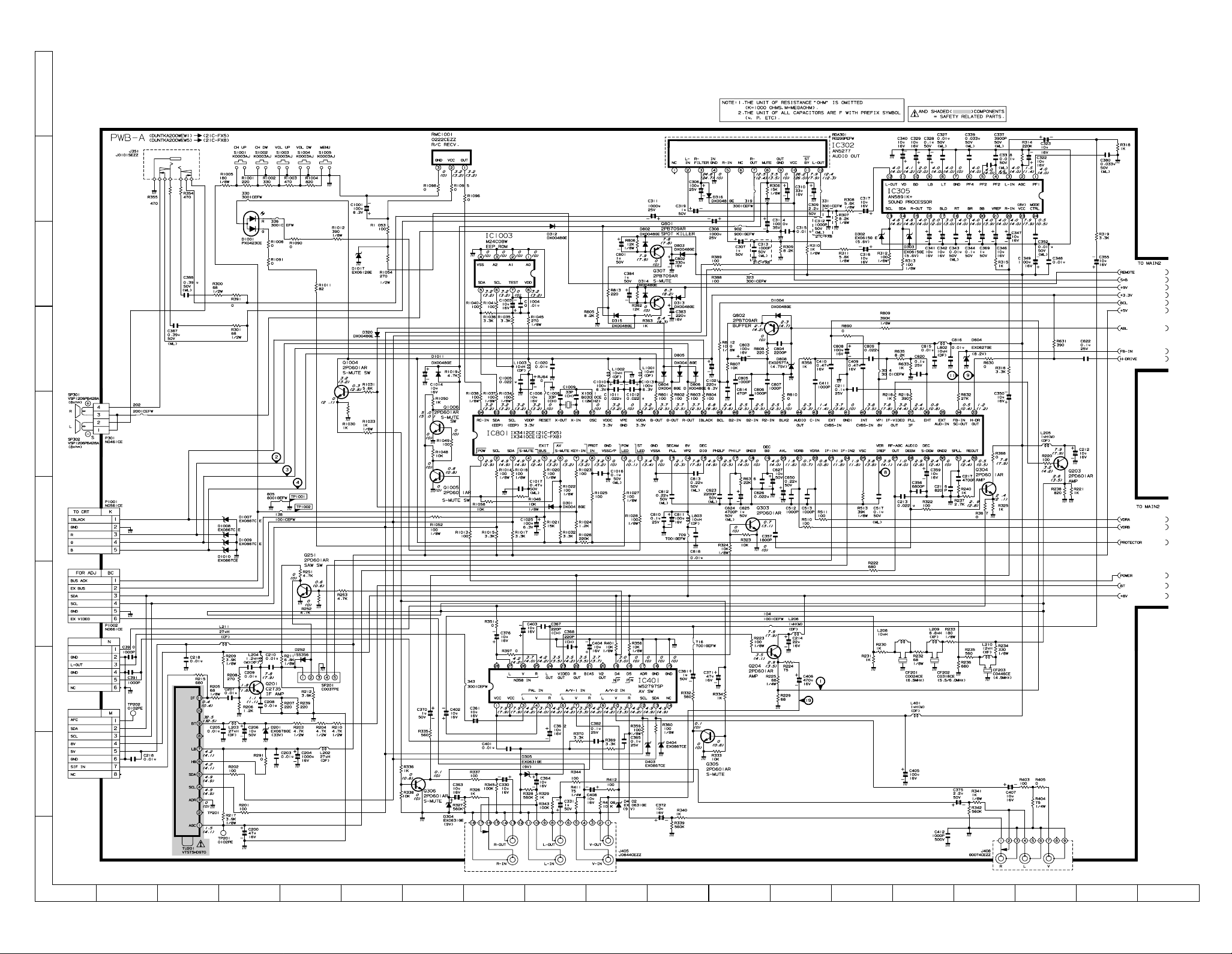
21C-FX1(C)/(G)
21C-FX5/FX8
SCHEMATIC DIAGRAM: MAIN Unit -1/2
21C-FX1(C)/(G)
21C-FX5/FX8
J
I
H
G
F
(MODEL 21C-FX5/FX8 )
E
D
C
B
A
1 2 3 4 5 6 7 8 9 10
11 12 13 14 15 16 17 18 19
3736
Page 2
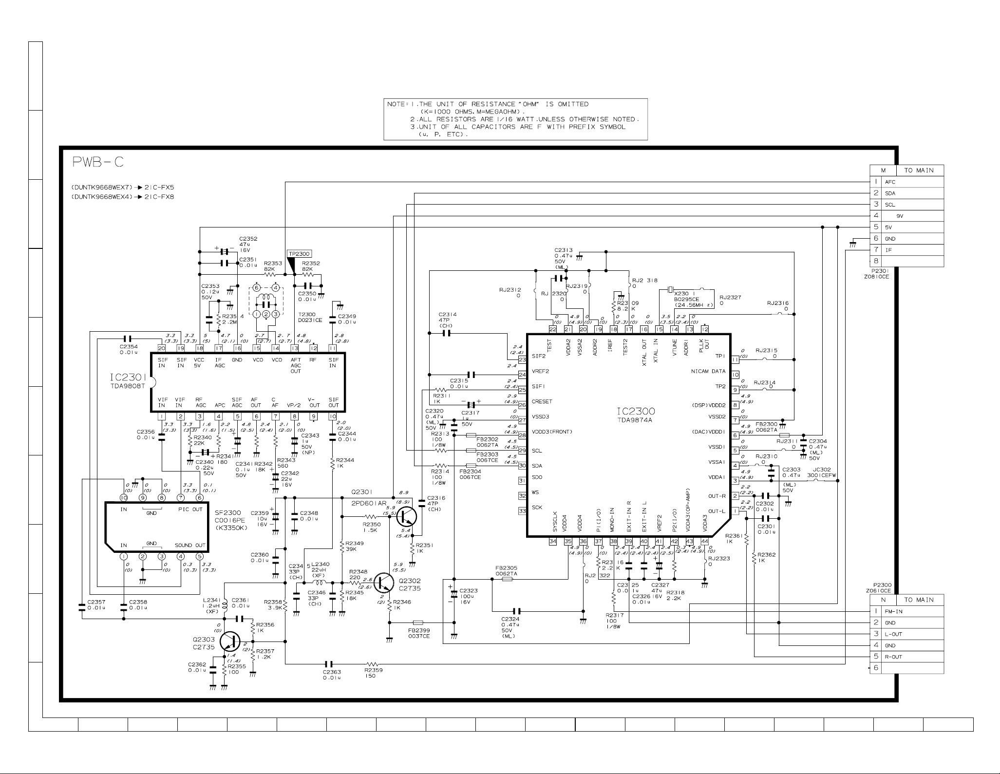
21C-FX1(C)/(G)
21C-FX5/FX8
SCHEMATIC DIAGRAM: NICAM Unit
21C-FX1(C)/(G)
21C-FX5/FX8
J
I
H
G
F
(MODEL 21C-FX5/FX8 )
E
D
C
B
A
1 2 3 4 5 6 7 8 9 10
11 12 13 14 15 16 17 18 19
4140
Page 3
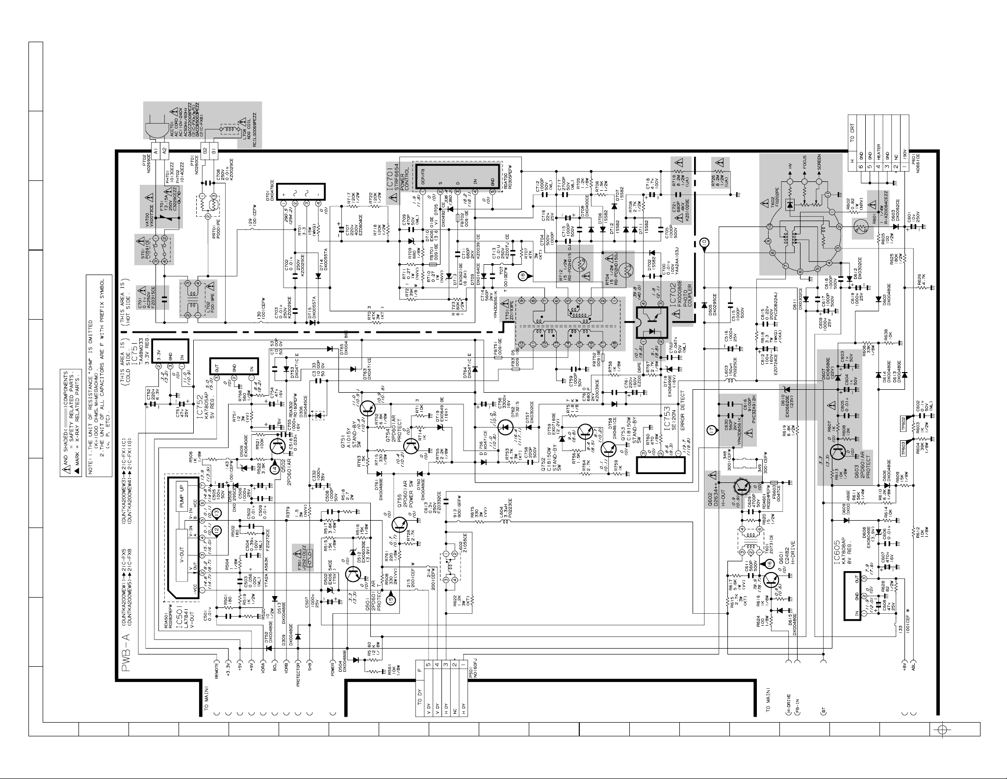
21C-FX1(C)/(G)
21C-FX5/FX8
SCHEMATIC DIAGRAM: MAIN Unit -2/2
J
I
H
G
21C-FX1(C)/(G)
21C-FX5/FX8
F
E
D
C
B
A
1 2 3 4 5 6 7 8 9 10
11 12 13 14 15 16 17 18 19
3938
Page 4
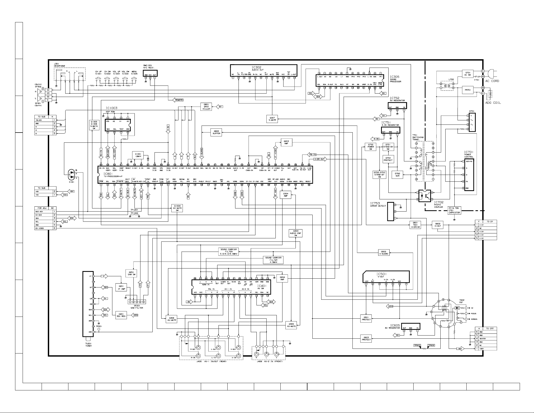
21C-FX1(C)/(G)
21C-FX5/FX8
BLOCK DIAGRAM - 1/3:MAIN BLOCK
21C-FX1(C)/(G)
21C-FX5/FX8
J
MODEL 21C-FX1(C)/1(G)
PWB-A MAIN BLOCK
I
H
G
F
E
D
C
B
A
1 2 3 4 5 6 7 8 9 10
11 12 13 14 15 16 17 18 19
4342
Page 5

21C-FX1(C)/(G)
21C-FX5/FX8
BLOCK DIAGRAM - 2/3:MAIN BLOCK
21C-FX1(C)/(G)
21C-FX5/FX8
J
MODEL 21C-FX5/FX8
PWB-A MAIN BLOCK
I
H
G
F
E
D
C
B
A
1 2 3 4 5 6 7 8 9 10
11 12 13 14 15 16 17 18 19
4544
Page 6

21C-FX1(C)/(G)
21C-FX5/FX8
BLOCK DIAGRAM - 3/3:
J
CRT / NICAM BLOCK
I
PWB-B CRT BLOCK
H
G
F
PWB-C NICAM BLOCK
(MODEL 21C-FX5/FX8)
E
D
C
B
A
1 2 3 4 5 6 7 8 9 10
46
Page 7

ADJUSTMENT PRECAUTIONS
This model’s setting are adjusted in two different ways: through the I
2
C bus control and in the conventional
analog manner. The adjustments via the I
2
C bus control include preset-only items and variable data.
1. Setting the service mode by the microprocessor.
1. Short TP1001 & TP1002 to switch to the service mode position, and the microprocessor is in input
mode. (Adjustment through the I2C bus control).
2. Press the CH DOWN / UP key on the remote controller to get ready to select the mode one by one.
3. Press the CH DOWN / UP key on the remote controller to select the modes reversibly one by one.
4. Using the VOLUME UP/ DOWN key on the remote controller, the data can be modified.
5. Disconnect TP1001 & TP1002 to switch to the normal mode (OFF) position, and the microprocessor
is in out of the service mode.
2. Factory Presetting.
1. Short TP1001 & TP1002 to switch to the service mode position and turn on the main power switch.
Initial values are automatically preset, only when a new EEPROM is used (Judge with the first 4 bytes).
2. The initial data are preset as listed in page 6 & 7.
3. Make sure the data need modify or not (Initial data).
Note: Once the chassis has been assembly together and ready to be POWER ON for the FIRST TIME,
make sure to short TP1001 & TP1002 to switch to the service mode position first and then turn on
the main power switch (See 2-(1) above).
Precaution: If haven’t done this initiation, it may possibly generate excessive Beam current.
3. For reference please check with memory map
(UAF-C Series type RH-IX3410CEN5, RH-IX3412CEN5 Attachment)
4. Trouble indications
If the set is interrupted by IIC bus line error, the following indicators work to identify a spot in trouble.
LED (RED) flashing: Flashing time Part's Ref.No. Remarks
2 IC1003 EEP ROM
3 IC801 TVPROCESSOR
4 IC401 AV SWITCH
5 IC305 SOUND PROCESSOR
6 IC2300 (NICAM/IGR) DECODER
8 TU201 TUNER
SERVICE MODE
(1) In the Service Mode, Key is used to select the mode in the following order.
AGC &
GEOMETRIC
MODE
↓
↓
↓
↓
↓
↓
↓
↓
↓
↓
↓
↓
↓
AGC Take Over Point (AGC)
Vertical Slope (V-LIN)
Vertical Amplitude(V-AMP)
Vertical Shift (V-CENT)
Horizontal shift (H-CENT)
East-West width (H-SIZE)
Horizontal Parallelogram (EW//)
East-west Parabola/Width (PARA)
East-west Upper Corner Parabola (COR(U))
East-west Lower Corner Parabola (COR(L))
East-west Trapezium (TRAPE)
Horizontal Bow (HB)
S-Correction (S-COR)
WHITE POINT
ADJ.
MODE
↓
↓
↓
↓
↓
↓
↓
↓
↓
White point Red Standard white temp.(DRI-RS)
White point Green Standard white temp. (DRI-GS)
White point Blue Standard white temp (DRI-BS)
White point Red Cold white temp. (DRI-RC)
White point Green Cold white temp. (DRI-GC)
White point Blue Cold white temp. (DRI-BC)
White point Red Warm white temp. (DRI-RW)
White point Green Warm white temp. (DRI-GW)
White point Blue Warm white temp. (DRI-BW)
SUB
ADJ.
MODE
↓
↓
↓
↓
↓
↓
↓
↓
↓
↓
↓
↓
↓
Max Volume (SUB-VOL)
Sub Contrast (SUB-CON)
Sub Colour (SUB-COL)
Sub Brightness (SUB-BRI)
Sub Tint (SUB-TINT)
Sub Sharpness (SUB-SHP)
Max Hotel Volume (HTL-VOL)
Hotel Program number (HTL-PRG)
Blue Back Contorast (BB-CON)
OSD RGB Reference (RGB)
Black Level off-set R (CUT-R)
Black Level off-set G (CUT-G)
Cathode Drive Level (CDL)
FORWARD : CH DOWN KEY
REVERSE : CH UP KEY
* ( ) means OSD display.
FORWARD : CH DOWN KEY
REVERSE : CH UP KEY
* ( ) means OSD display.
AGC &
GEOMETRIC
MODE
WHITE POINT
ADJ.
MODE
SUB
ADJ.
MODE
Y-DELAY
ADJ.
MODE
MISC.
OPTION
MODE
IC
OPTION
MODE
OFFSET
ADJ.
MODE
3
3-1 3-2
21C-FX1(C)/(G)
21C-FX5/FX8
Page 8

Bass Mix for AN7396K (BM-ON)
Bass Mix Effect for AN7396K (BM-EFF)
AGC for AN7396 or AN5891 (AGC-ON)
AGC Adjust for AN7396K or AN5891
(AGC-ADJ)
NICAM AGC (AGC-N)
NICAM AGC Gain adjust (GAIN-N)
FM Output Level (FM-LV)
IGR Output Level (IGR-LV)
NICAM Output Level (B/G) (BG-NLY)
NICAM Output Level (I) (I-NLV)
NICAM Output Level (D/K) (DK-NLV)
NICAM lower error limit (LOW-ERR)
NICAM upper error limit (UP-ERR)
IGR Stereo R ch gain adjust
(tda9873) (IGR-STR)
Vertical Scan Disable (VSD)
Black Stretch (BKS)
Automatic Volume Leveling (AVL)
Fast Filter IF-PLL (FFI)
Enable Vertical Guard
(RGB blanking) (EVG)
EHT Tracking mode [HCO] (EHT)
Overscan Switch OFF (OSO)
Auto Colour Limit (ACL)
Forced Colour ON (FCO)
COLOUR OFFSET (PAL) (COL-OP)
COLOUR OFFSET (SECAM) (COL-OS)
COLOUR OFFSET (NTSC358) (COL-O3)
COLOUR OFFSET (NTSC443) (COL-O4)
SHARPNESS OFFSET(PAL) (SHP-OP)
SHARPNESS OFFSET(SECAM) (SHP-OS)
SHARPNESS OFFSET(NTSC358) (SHP-O3)
SHARPNESS OFFSET(NTSC443) (SHP-O4)
Y-DELAY
ADJ.
MODE
↓
↓
↓
↓
↓
↓
↓
↓
↓
↓
Y-Delay time for PAL (TV)
(DL-PT)
Y-Delay time for SECAM (TV)
(DL-ST)
Y-Delay time for N358 (TV)
(DL-3T)
Y-Delay time for N443 (TV)
(DL-4T)
Y-Delay time for B/W (TV)
(DL-TV)
Y-Delay time for PAL (AV)
(DL-PA)
Y-Delay time for SECAM (AV)
(DL-SA)
Y-Delay time for N358 (AV)
(DL-3A)
Y-Delay time for N443 (AV)
(DL-4A)
Y-Delay time for B/W (AV)
(DL-AV)
OFFSET
ADJ.
MODE
↓
↓
↓
↓
↓
↓
↓
↓
IC
OPTION
MODE
↓
↓
↓
↓
↓
↓
↓
↓
↓
↓
↓
↓
↓
↓
↓
↓
↓
↓
↓
↓
↓
↓
↓
Sound system M (S-M)
Sound system DK (S-DK)
Sound system I (S-I)
Sound system BG (S-BG)
Playback SECAM (P-SECAM)
FE (RF) NTSC 3.58 (F-N358)
FE (RF) NTSC 4.43 (F-N443)
FE (RF) SECAM (F-SECAM)
Video Mute at Ident loss (VMI)
Video Mute at program
/source Change (VMC)
Hotel mode (HTL)
Reduced FM demodulator Gain
(for BTSC sig) (BTSC)
Number of external AV sources (AV)
FM Window Selection (FMWS)
Sound Mute bit 0 (SM0)
Sound Mute bit 1 (SM1)
Thai language (THA)
Arabic language (ARA)
Malay language (MAL)
Chinese language (CHI)
French language (FRE)
Russian language (RUS)
A
↓
↓
↓
↓
↓
↓
↓
↓
↓
↓
↓
↓
↓
↓
↓
↓
↓
↓
↓
↓
↓
↓
↓
↓
Forced V-SYNC slicing level (FSL)
Sync of OSD (HP2)
IF AGC speed bit0 (AGC0)
IF AGC speed bit1 (AGC1)
Phi 1 time constant for FE(RF) (FOA-FE)
Phi 2 time constant for FE(RF) (FOB-FE)
Phi 1 time constant for AV (FOA-AV)
Phi 2 time constant for AV (FOB-AV)
Teletext (TXT)
Teletext Western or Eastern characters (TXT-WE)
Teletext pan-European language (TXT-EURO)
IF frequency selection (IF-38.0)
Charge pump (CP)
AN5890 Sound processor present (AN5890)
AN5891 sound processor present (AN5891)
AN7396 sound processor present (AN7396)
NICAM decoding enabled (NICAM)
IGR decoding enabled (IGR)
GAME mode enabled (GAME)
BIL enabled (BIL)
LED Blink Speed When On-Timer is active (LED-F)
PWM Volume table for mono (MSA)
Output Vertical Guard (NDF)
OSD "IGR" or "A2" Display (A2)
MISC.
OPTION
MODE
↓
↓
↓
↓
↓
↓
↓
↓
↓
↓
↓
↓
↓
↓
↓
↓
↓
↓
↓
↓
↓
↓
↓
A
4
4-1 4-2
21C-FX1(C)/(G)
21C-FX5/FX8
Page 9

USER DATA
CONTRAST MAX (64/64)
COLOUR CENT (32/64)
BRIGHTNESS CENT (32/64)
TINT CENT (32/64)
SHARPNESS CENT (32/64)
WHITE TEMP CENT (32/64)
TREBLE CENT (32/64)
BASS CENT (32/64)
SURROUND OFF
BALANCE CENT (32/64)
S-VOLUME MIN (1/64)
BLUE BACK OFF
C SYSTEM AUTO
S SYSTEM *1
USER DATA IN SERVICE MODE
* While SERVICE mode ON, EEPROM DATA will switch to the service data.
Also, once SERVICE mode OFF, EEPROM will switch back to previous USER DATA.
* In the service mode, the user data establish as below,
*1: For each CH, data is
same as before switch
to Service Mode.
* Direct Key-in
MODE KEY-IN KEY
AGC FUNCTION
SUB-BRI BRIGHTNESS UP
DRI-GS TEXT
DRI-BS PICTURE
CUT-R SKIP
CUT-G F2
V-LIN CONTRAST DOWN
V-CENT BRIGHTNESS DOWN
V-AMP COLOUR DOWN
H-CENT TINT DOWN
H-SIZE BALANCE RIGHT
PARA TREBLE UP
TRAPE BASS UP
EW// SHARPNESS DOWN
SUB-COL COLOUR UP
SUB-TINT TINT UP
EEPROM ITEMS OSD DATA LENGTH
INITIAL DATA
FIX/ADJ REMARK
AGC Take Over Point AGC 0 ~ 63 14 (20) ADJ
Vertical Slope V-LIN 0 ~ 63 32 ADJ
Vertical Amplitude V-AMP 0 ~ 63 32 ADJ
Vertical Shift V-CENT 0 ~ 63 32 (15) ADJ
Horizontal shift H-CENT 0 ~ 63 32 ADJ
East-West width H-SIZE 0 ~ 63 32 FIX
Horizontal Parallelogram EW / / 0 ~ 63 32 FIX
East-west Parabola/Width PARA 0 ~ 63 32 FIX
East-west Upper Corner Parabola COR (U) 0 ~ 63 32 FIX
East-west Lower Corner Parabola COR (L) 0 ~ 63 32 FIX
East-west Trapezium TRAPE 0 ~ 63 32 FIX
Horizontal Bow HB 0 ~ 63 32 FIX
S-Correction S-COR 0 ~ 63 0 (24) FIX
White point Red Standard white temp. DRI-RS 0 ~ 63 32 FIX
White point Green Standard white temp. DRI-GS 0 ~ 63 32 ADJ
White point Blue Standard white temp DRI-BS 0 ~ 63 32 ADJ
White point Red Cold white temp. DRI-RC 0 ~ 63 25 FIX *2
White point Green Cold white temp. DRI-GC 0 ~ 63 32 FIX *2
White point Blue Cold white temp. DRI-BC 0 ~ 63 32 FIX (DRI-BS) DATA
White point Red Warm white temp. DRI-RW 0 ~ 63 32 FIX
White point Green Warm white temp. DRI-GW 0 ~ 63 32 FIX (DRI-GS)-7 DATA
White point Blue Warm white temp. DRI-BW 0 ~ 63 32 FIX (DRI-BS)-7 DATA
Max Volume SUB-VOL 0 ~ 60 60 FIX
Sub Contrast SUB-CON 0 ~ 63 63 FIX
Sub Colour SUB-COL 0 ~ 63 32 (20) ADJ
Sub Brightness SUB-BRI 0 ~ 63 32 (20) ADJ
Sub Tint SUB-TINT 0 ~ 63 32 (30) ADJ
Sub Sharpness SUB-SHP 0 ~ 63 32 FIX
Max Hotel Volume HTL-VOL 0 ~ 60 30 FIX
Hotel Program number HTL-PRG
0 ~ 99 OR >99 FOR NONE
255 FIX
Blue Back Contorast BB-CON 0 ~ 15 10 FIX
OSD RGB Reference RGB 0 ~ 15 15 (8) FIX
Black Level off-set R CUT-R 0 ~ 63 32 ADJ
Black Level off-set G CUT-G 0 ~ 63 32 ADJ
Cathode Drive Level CDL 0 ~ 15 0 (9) FIX
Y-Delay time for PAL (TV) DL-PT 0 ~ 15 12 FIX
Y-Delay time for SECAM (TV) DL-ST 0 ~ 15 15 FIX
Y-Delay time for N358 (TV) DL-3T 0 ~ 15 12(5) FIX
Y-Delay time for N443 (TV) DL-4T 0 ~ 15 12(5) FIX
Y-Delay time for B/W (TV) DL-TV 0 ~ 15 12 FIX
Y-Delay time for PAL (AV) DL-PA 0 ~ 15 12 FIX
Y-Delay time for SECAM (AV) DL-SA 0 ~ 15 15 FIX
Y-Delay time for N358 (AV) DL-3A 0 ~ 15 12(5) FIX
Y-Delay time for N443 (AV) DL-4A 0 ~ 15 12(5) FIX
Y-Delay time for B/W (AV) DL-AV 0 ~ 15 12 FIX
After short TP1001 & TP1002, and turn on the MAIN POWER switch, read data from EEPROM address
00H ~ 03H, and compare to the list below, if different, initialize the EEPROM.
Address : Data Address : Data
00H : 55H 02H : 53H
01H : 41H 03H : 36H
5
21C-FX1(C)/(G)
21C-FX5/FX8
5-1 5-2
Page 10

21C-FX1(C)/(G)
EEPROM ITEMS OSD DATA LENGTH
INITIAL DATA
FIX/ADJ REMARK
COLOUR OFFSET (PAL) COL-OP 0 ~ 15 8 FIX *3
COLOUR OFFSET (SECAM) COL-OS 0 ~ 15 8 FIX *3
COLOUR OFFSET (NTSC358) COL-O3 0 ~ 15 4 FIX *3
COLOUR OFFSET (NTSC443) COL-O4 0 ~ 15 4 FIX *3
SHARPNESS OFFSET(PAL) SHP-OP 0 ~ 15 8 FIX
SHARPNESS OFFSET(SECAM) SHP-OS 0 ~ 15 4 FIX
SHARPNESS OFFSET(NTSC358) SHP-O3 0 ~ 15 12 FIX
SHARPNESS OFFSET(NTSC443) SHP-O4 0 ~ 15 8 FIX
Bass Mix for AN7396K BM-ON
0(DISABLE)/1(ENABLE)
0 FIX
Bass Mix Effect for AN7396K BM-EFF 0 ~ 3 2 FIX
AGC for AN7396 or AN5891 AGC-ON
0(DISABLE)/1(ENABLE)
1 FIX
AGC Adjust for AN7396K or AN5891 AGC-ADJ 0 ~ 3 3 FIX
NICAM AGC AGC-N
0(DISABLE)/1(ENABLE)
0 FIX
NICAM AGC Gain adjust GAIN-N 0 ~ 31 0 FIX
FM Output Level FM-LV 0 ~ 30 15 (22) FIX
IGR Output Level IGR-LV 0 ~ 30 16 (23) FIX
NICAM Output Level (B/G) BG-NLV 0 ~ 30 13 (20) FIX
NICAM Output Level (I) I-NLV 0 ~ 30 18 (25) FIX
NICAM Output Level (D/K) DK-NLV 0 ~ 30 13 (20) FIX
NICAM lower error limit LOW-ERR 0 ~ 255 35 FIX
NICAM upper error limit UP-ERR 0 ~ 255 70 FIX
IGR Stereo R ch gain adjust(tda9873) IGR-STR 0 ~ 13 6 FIX
Vertical Scan Disable VSD
0 or 1 (not Stored)
0 FIX
Black Stretch BKS
0(DISABLE)/1(ENABLE)
1 FIX
Automatic Volume Leveling AVL
0(DISABLE)/1(ENABLE)
1 FIX
Fast Filter IF-PLL FFI
0(DISABLE)/1(ENABLE)
0 FIX
Enable Vertical Guard (RGB blanking) EVG
0(DISABLE)/1(ENABLE)
1 FIX
EHT Tracking mode [HCO] EHT
0(DISABLE)/1(ENABLE)
1 FIX
Overscan Switch Off OSO
0(DISABLE)/1(ENABLE)
0 FIX
Auto Colour Limit ACL
0(DISABLE)/1(ENABLE)
0 (1) FIX
Forced Colour ON FCO
0(DISABLE)/1(ENABLE)
0 FIX
Sound system M S-M
0(DISABLE)/1(ENABLE)
*1 FIX
Sound system DK S-DK
0(DISABLE)/1(ENABLE)
*1 FIX
Sound system I S-I
0(DISABLE)/1(ENABLE)
*1 FIX
Sound system BG S-BG
0(DISABLE)/1(ENABLE)
*1 FIX
Playback SECAM P-SECAM
0(DISABLE)/1(ENABLE)
*1 FIX
FE (RF) NTSC 3.58 F-N358
0(DISABLE)/1(ENABLE)
*1 FIX
FE (RF) NTSC 4.43 F-N443
0(DISABLE)/1(ENABLE)
*1 FIX
FE (RF) SECAM F-SECAM
0(DISABLE)/1(ENABLE)
*1 FIX
Video Mute at Ident loss VMI
0(DISABLE)/1(ENABLE)
1 FIX
Video Mute at program/source Change VMC
0(DISABLE)/1(ENABLE)
1 FIX
Hotel mode HTL
0(DISABLE)/1(ENABLE)
0 FIX
Reduced FM demodulator Gain (for BTSC sig) BTSC
0(DISABLE)/1(ENABLE)
0 FIX
Number of external AV sources AV
0 FOR 1 AV / 1 FOR 2 AV
1 FIX
FM Window Selection FMWS
0(DISABLE)/1(ENABLE)
0 FIX
Sound Mute bit 0 SM0
0(DISABLE)/1(ENABLE)
1 FIX
Sound Mute bit 1 SM1
0(DISABLE)/1(ENABLE)
0 FIX
Thai language THA
0(DISABLE)/1(ENABLE)
0 FIX
Arabic language ARA
0(DISABLE)/1(ENABLE)
1 FIX
Malay language MAL
0(DISABLE)/1(ENABLE)
1 FIX
Chinese language CHI
0(DISABLE)/1(ENABLE)
1 FIX
French language FRE
0(DISABLE)/1(ENABLE)
1 FIX
Russian language RUS
0(DISABLE)/1(ENABLE)
1 FIX
EEPROM ITEMS OSD DATA LENGTH
INITIAL DATA
FIX/ADJ REMARK
Forced V-SYNC slicing level FSL
0(DISABLE)/1(ENABLE)
0 FIX
Sync of OSD HP2
0 FOR Ph1 / 1 FOR Ph2
0 FIX
IF AGC speed bit0 AGC0
0(DISABLE)/1(ENABLE)
1 FIX
IF AGC speed bit1 AGC1
0(DISABLE)/1(ENABLE)
0 FIX
Phi 1 time constant for FE(RF) FOA-FE
0(DISABLE)/1(ENABLE)
0 FIX
Phi 2 time constant for FE(RF) FOB-FE
0(DISABLE)/1(ENABLE)
0 FIX
Phi 1 time constant for AV FOA-AV
0(DISABLE)/1(ENABLE)
1 FIX
Phi 2 time constant for AV FOB-AV
0(DISABLE)/1(ENABLE)
1 FIX
Teletext TXT
0(DISABLE)/1(ENABLE)
*1 FIX
Teletext Western or Eastern characters TXT-WE
0(DISABLE)/1(ENABLE)
0 FIX
0 (teletext pan-
Teletext pan-European language TXT-EURO
european language) /
0 FIX
depends on delivery
(Arabic/Russian))
IF frequency selection IF-38.0
0 (IF FREQUENCY 38.9) /
0 FIX
1 (IF FREQUENCY 38.0)
0 (FAST TUNING) /
Charge pump CP
1 (MODERATE
0(1) FIX
SPEED TUNING)
AN5890 Sound processor present AN5890
0(DISABLE)/1(ENABLE)
1(0) FIX
AN5891 sound processor present AN5891
0(DISABLE)/1(ENABLE)
0(1) FIX
AN7396 sound processor present AN7396
0(DISABLE)/1(ENABLE)
0 FIX
NICAM decoding enabled NICAM
0(DISABLE)/1(ENABLE)
*1 FIX
IGR decoding enabled IGR
0(DISABLE)/1(ENABLE)
*1 FIX
GAME mode enabled GAME
0(DISABLE)/1(ENABLE)
0 FIX
BIL enabled BIL
0(DISABLE)/1(ENABLE)
0 FIX
LED blink Speed when On-Timer is active LED-F 0(62.5Hz)/1(1Hz) 0 FIX
PWM volume table for MONO MSA
0(original table)/1(new table)
0 FIX
Output Vertical Guard NDF
0(lgnore)/1(accopl)
0(1) FIX
OSD "IGR" or "A2" display A2
0(display IGR)/1(display A2)
*1 FIX
EEPROM ITEMS OSD DATA LENGTH
FIX/ADJ
*(1) *(2) *(3)
Sound system M S-M
0(DISABLE)/1(ENABLE)
0 (1) 0 (1) 0 (1)
Sound system DK S-DK
0(DISABLE)/1(ENABLE)
111
Sound system I S-I
0(DISABLE)/1(ENABLE)
111
Sound system BG S-BG
0(DISABLE)/1(ENABLE)
111
Playback SECAM P-SECAM
0(DISABLE)/1(ENABLE)
111
FE (RF) NTSC 3.58 F-N358
0(DISABLE)/1(ENABLE)
0 (1) 0 (1) 0 (1)
FE (RF) NTSC 4.43 F-N443
0(DISABLE)/1(ENABLE)
111
FE (RF) SECAM F-SECAM
0(DISABLE)/1(ENABLE)
111
Teletext TXT
0(DISABLE)/1(ENABLE)
0 (1) 0 0
NICAM decoding enabled NICAM
0(DISABLE)/1(ENABLE)
0 (1) 0 (1) 0
IGR decoding enabled IGR
0(DISABLE)/1(ENABLE)
0 (1) 0 (1) 0
OSD "IGR" or "A2" display A2
0(display IGR)/1(display A2)
0 (1) 0 (1) 0
NOTE :
Please set the EEPROM initial data according to the value in parenthesis ( ) before adjustment.
Fixed data, please do not change without specific instruction.
*1: Please refer the following table.
MODEL : *(1) : 21C-FX5 *(2) :21C-FX8 *(3) : 21C-FX1(C)/(G)
*2 :DRI-RC = 27, DRI-GC = (DRI-GS)-5 for 21C-FX1(G)
DRI-RC = 25, DRI-GC = (DRI-GS)-7 for the other models
*3 :After Adjust SUB-COL then change:
1.COL-0P from 8 to 14
2.COL-0S from 8 to 14
3.COL-03 from 4 to 10
4.COL-04 from 4 to 10
21C-FX5/FX8
6
6-1 6-2
Page 11

MCL2
CH-NO Fv (MHz) SOUND SYS
0 590.25 B/G
1 46.25 B/G
2 64.25 B/G
3 86.25 B/G
4 95.25 B/G
5 138.25 B/G
6 175.25 B/G
7 182.25 B/G
8 189.25 B/G
9 196.25 B/G
10 209.25 B/G
11 216.25 B/G
12
13
14
15
16
17
18
19
20
21
22
23
24
25
26
27
28 527.25 B/G
29
30
31
32
33
34
35
36
37 590.25 B/G
38
39
40
41 48.25 B/G
42 62.25 B/G
43 77.25 D/K
44 175.25 B/G
45 183.25 D/K
46 191.25 D/K
47 210.25 B/G
48 224.25 B/G
49 487.25 I
50 503.25 B/G
51 575.25 B/G
52 599.25 B/G
53 621.25 M
54 639.25 D/K
55 735.25 I
56 767.25 B/G
57 815.25 B/G
58 855.25 I
59 91.25 M
60 183.25 M
MCL1
CH-NO Fv (MHz) SOUND SYS
0
1 48.25 B/G
2 62.25 B/G
3 77.25 D/K
4 175.25 B/G
5 182.25 B/G
6 183.25 D/K
7 191.25 D/K
8 196.25 B/G
9 199.25 M
10 210.25 B/G
11 224.25 B/G
12 471.25 B/G
13 487.25 I
14 503.25 B/G
15 575.25 B/G
16 583.25 B/G
17 599.25 B/G
18 621.25 M
19 639.25 D/K
20 703.25 B/G
21 735.25 I
22 767.25 B/G
23 815.25 B/G
24 855.25 I
25 855.25 B/G
26 55.25 M
27 83.25 M
28 183.25 M
29 193.25 M
30 217.25 M
31 471.25 M
32 477.25 M
33 693.25 M
34 885.25 M
35 112.25 B/G
36 168.25 B/G
37
38 294.25 B/G
39 463.25 B/G
40
41 647.25 B/G
42 663.25 B/G
43 679.25 B/G
44 174.95 B/G
45 175.55 B/G
MCL2
CH-NO Fv (MHz) SOUND SYS
61 193.25 M
62 217.25 M
63 471.25 M
64 693.25 M
65 112.25 B/G
66 168.25 B/G
67 294.25 B/G
68 463.25 B/G
69 174.95 B/G
70 175.55 B/G
INITIAL SETTING
In service mode, after execute select POS 1, store the following tuning data in EEPROM.
SHIPPING SETTING & CHECKING
THE FOLLOWING DEFAULT DATA HAS BEEN FACTORY-SET FOR THE EEPROM.
ITEMS DATA SETTING
LAST PROGRAM/CHANNEL 1
FLASHBACK PROGARM/CH 1
DIGIT 2
C-SYSTEM AUTO
S-SYSTEM *1
SKIP OFF
AFC ON
VOLUME 1
CONTRAST 60 (MAX)
COLOUR 0 (CENTER)
BRIGHTNESS 0 (CENTER)
TINT 0 (CENTER)
SHARPNESS 0 (CENTER)
WHITE TEMP STANDARD
TREBLE 0 (CENTER)
BASS 0 (CENTER)
SURROUND OFF
SURROUND LEVEL 0 (CENTER)
BALANCE 0 (CENTER)
REMINDER TIMER
IN-ACTIVE, "--:--"
ON TIMER
IN-ACTIVE, "--:--"
OFF TIMER
IN-ACTIVE, "--:--"
R/C POWER POWER-ON
LANGUAGE *1
BLUE BACK MUTE ON
HOTEL MODE OFF
0 CHANNEL SKIP ON
LAST TV/AV TV
FACTORY SETTING BY MODEL
(Reference: Geomagnetism Adjustment)
*1: Please refer defaults for LANGUAGE and
SOUND SYSTEM per MODEL as follows,
INITIAL DESTINATION LANGUAGE
SOUND
SYSTEM
1 CHINA CHINESE D/K
2 HONGKONG CHINESE I
3 SINGAPORE ENGLISH B/G
4 MIDDLE EAST ARABIC B/G
5 RUSSIA RUSSIAN D/K
6 MALAYSIA MALAY B/G
7 TAHITI FRENCH D/K
8 AUSTRALIA ENGLISH B/G
MODEL MAGNEIC FIELD(V, H) nT BACKGROUND LANG. S-SYS LANG QTY
B 20,000 40,000 12300K CHINESE I 6
C (SINGAPORE) -10,000 40,000 12300K ENGLISH B/G 6
G 30,000 20,000 18000K ARABIC B/G 6
*NOTE FOR OSD TYPE
ENGLISH/CHINESE/FRENCH/ARABIC/MALAY/RUSSIAN
7
7-1 7-2
21C-FX1(C)/(G)
21C-FX5/FX8
 Loading...