

SGS Thomson Microelectronics TIP42A, TIP42C, TIP41C, TIP41B, TIP41A Datasheet
TIP41A/41B/41C
®
COMPLEMENTARY SILICON POWER
■
COMPLEMENTARY PNP - NPN DEVICES
DESCRIPTION
The TIP41A, TIP41B and TIP41C are silicon
Epitaxial-Base NPN power transistors mounted in
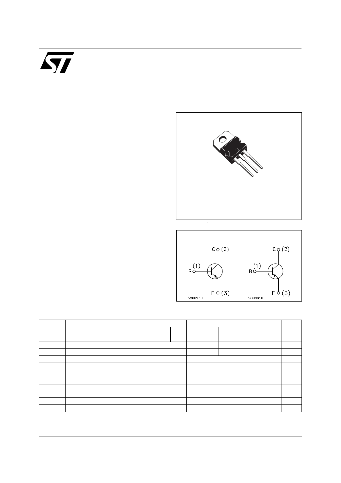
Jedec TO-220 plastic package. They are intented
for use in medium power linear and switching
applications.
The TIP41A and TIP41C complementary PNP
types are TIP42A and TIP42C respectively.
TIP42A/42C
TRANSISTORS
3
2
1
TO-220
INTERNAL SCHEMATIC DIAGRAM
ABSOLUTE MAXIMUM RATINGS
Symbol Parameter Value Unit
NPN TIP41A TIP41B TIP41C
PNP TIP42A TIP42C
V
V
V
I
P
T
For PNP types voltage and current values are negative.
Collector-Base Voltage (IE = 0) 60 80 100 V
CBO
Collector-Emitter Voltage (IB = 0) 60 80 100 V
CEO
Emitter-Base Voltage (IC = 0) 5 V
EBO
Collector Current 6 A
I
C
Collector Peak Current 10 A
CM
I
Base Current 3 A
B
Total Dissipation at T
tot
T
Storage Temperature -65 to 150
stg
T
Max. Operating Junction Temperature 150
j
case
amb
≤ 25 oC
≤ 25 oC
65
2
W
W
o
C
o
C
October 1999
1/4
TIP41A/TIP41B/TIP41C/T IP42A /T IP 42C
THERMAL DATA
R
thj-case
R
thj-amb
Thermal Resistance Junction-case Max
Thermal Resistance Junction-ambient Max
1.92
62.5
o
C/W
o
C/W
ELECTRICAL CHARACTERISTICS
= 25 oC unless otherwise specified)
(T
case
Symbol Parameter Test Conditions Min. Typ. Max. Unit
I
CEO
I
CES
I
EBO
V
CEO(sus)
V
CE(sat)
Collector Cut-off
Current (I
= 0)
B
Collector Cut-off
Current (V
BE
= 0)
Emitter Cut-off Current
(I
= 0)
C
* Collector-Emitter
Sustaining Voltage
(I
= 0)
B
* Collector-Emitter
TIP41A/42A
for
TIP41B/41C/42C
for
TIP41A/42A
for
TIP41B
for
TIP41C/42C
for
= 5 V 1 mA
V
EB
= 30 mA
I
C
TIP41A/42A
for
TIP41B
for
TIP41C/42C
for
V
V
V
V
CE
CE
V
CE
CE
CE
= 30 V
= 60 V
= 60 V
= 80 V
= 100 V
0.7
0.7
0.4
0.4
0.4
60
80
100
IC = 6 A IB = 0.6 A 1.5 V
Saturation Voltage
V
* Base-Emitter Voltage IC = 6 A VCE = 4 V 2 V
BE(on)
h
* DC Current Gain IC = 0.3 A VCE = 4 V
FE
h
Small Signal Current
fe
Gain
∗
Pulsed: Pulse duration = 300 µs, duty cycle ≤ 2 %
For PNP types voltage and current values are negative.
I
= 3 A VCE = 4 V
C
IC = 0.5 A VCE = 10 V f = 1 KHz
I
= 0.5 A VCE = 10 V f = 1 MHz
C
30
15 75
20
3
mA
mA
mA
mA
mA
V
V
V
2/4
 Loading...