

Page 1
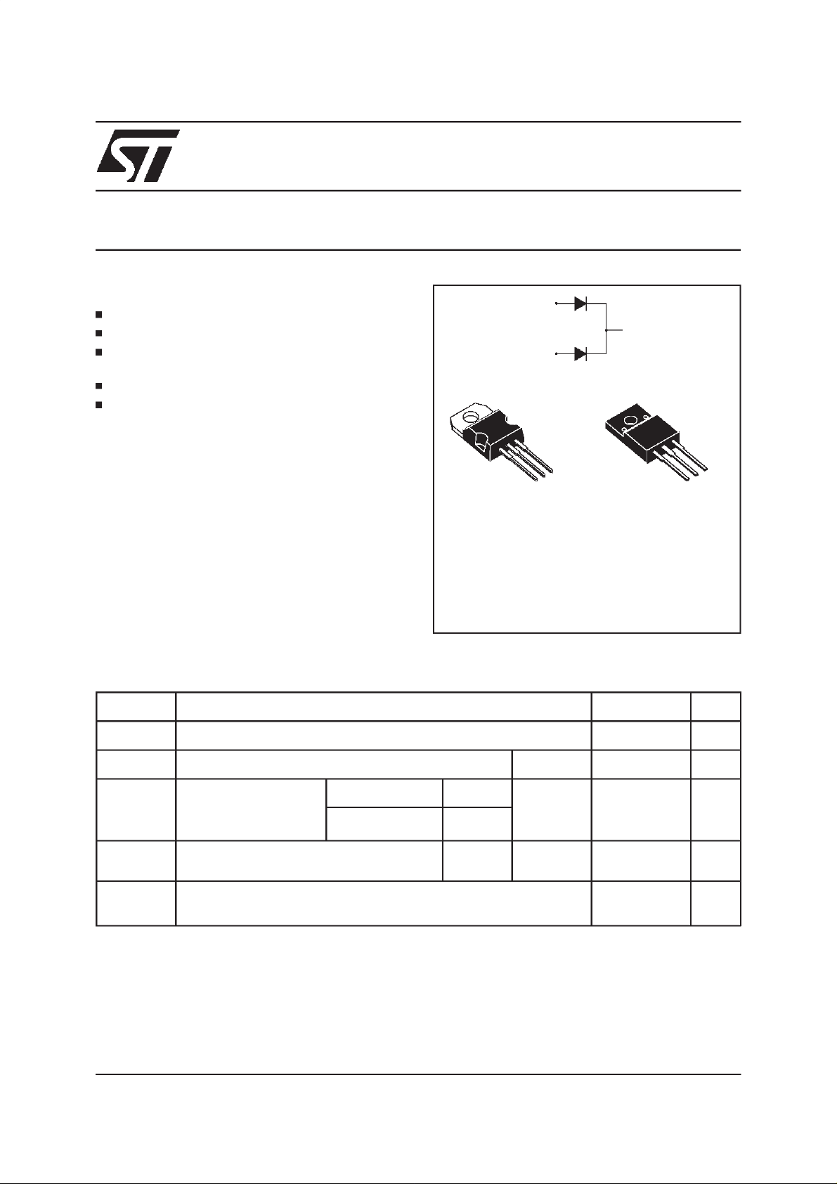
ULTRA FAST RECOVERY RECTIFIERDIODES
FEATURES
SUITEDFOR SMPS
LOW LOSSES
LOW FORWARD AND REVERSERECOVERY
TIME
HIGHSURGECURRENTCAPABILITY
HIGHAVALANCHEENERGYCAPABILITY
STPR620CT
STPR620CF
A1
K
A2
A2
K
DESCRIPTION
A1
Low cost dual center tap rectifiersuitedfor switchmode powersupply and high frequency DC to DC
converters.
TO220AB
(Plastic)
ISOWATT220AB
(Plastic)
Packagedin TO220AB and ISOWATT220AB,this
deviceis intended for usein low voltage,high fre-
STPR620CT
STPR620CF
quency inverters, free wheeling and polarity protectionapplications.
ABSOLUTE MAXIMUM (limiting values)
Symbol Parameter Value Unit
V
RRM
I
F(RMS)
I
F(AV)
Repetitivepeakreversevoltage 200 V
RMSforwardcurrent
Averageforward
Perdiode
TO220AB Tc=125°C Per diode
10 A
3A
current
6
30 A
I
FSM
δ =0.5
ISOWATT220AB Tc=120°C Per device
Surgenon repetitiveforwardcurrent
tp=10ms
Perdiode
sinusoidal
T
stg
Tj
Storagetemperaturerange
Maximumjunctiontemperature
- 65 to+ 150
- 65 to+ 150
A1
A2
K
°C
°
C
October 1999-Ed:2A
1/6
Page 2
STPR620CT/STPR620CF
THERMALRESISTANCES
Symbol Parameter Value Unit
R
th (j-c)
Whenthe diodes1 and 2 are used simultaneously:
∆
Tj(diode1) = P(diode1) x Rth(j-c)(Per diode) + P(diode2) x Rth(c)
ELECTRICAL CHARACTERISTICS
STATICCHARACTERISTICS
Symbol TestConditions Min. Typ. Max. Unit
I
*
R
V
F**
Pulse test :
* tp= 5ms, δ <2%
** tp = 380 µs,δ <2%
Junctionto case
TO220AB Perdiode
ISOWATT220AB Perdiode
T
=25°CV
j
T
= 100°C0.6mA
j
Tj= 125°CI
= 125°CI
T
j
T
=25°CI
j
=V
R
RRM
=3 A 0.99 V
F
=6 A 1.20
F
=6 A 1.25
F
6.5
8.5
50
°
C/W
µ
A
RECOVERYCHARACTERISTICS
Symbol TestConditions Min. Typ. Max. Unit
trr T
tfr T
V
FP
=25°CI
j
=25°CI
j
Tj=25°CI
=0.5A
F
I
=1A
R
=1A
F
=1.1 x V
V
FR
=1A tr =10 ns 3 V
F
Irr = 0.25A 30 ns
tr= 10ns 20 ns
F
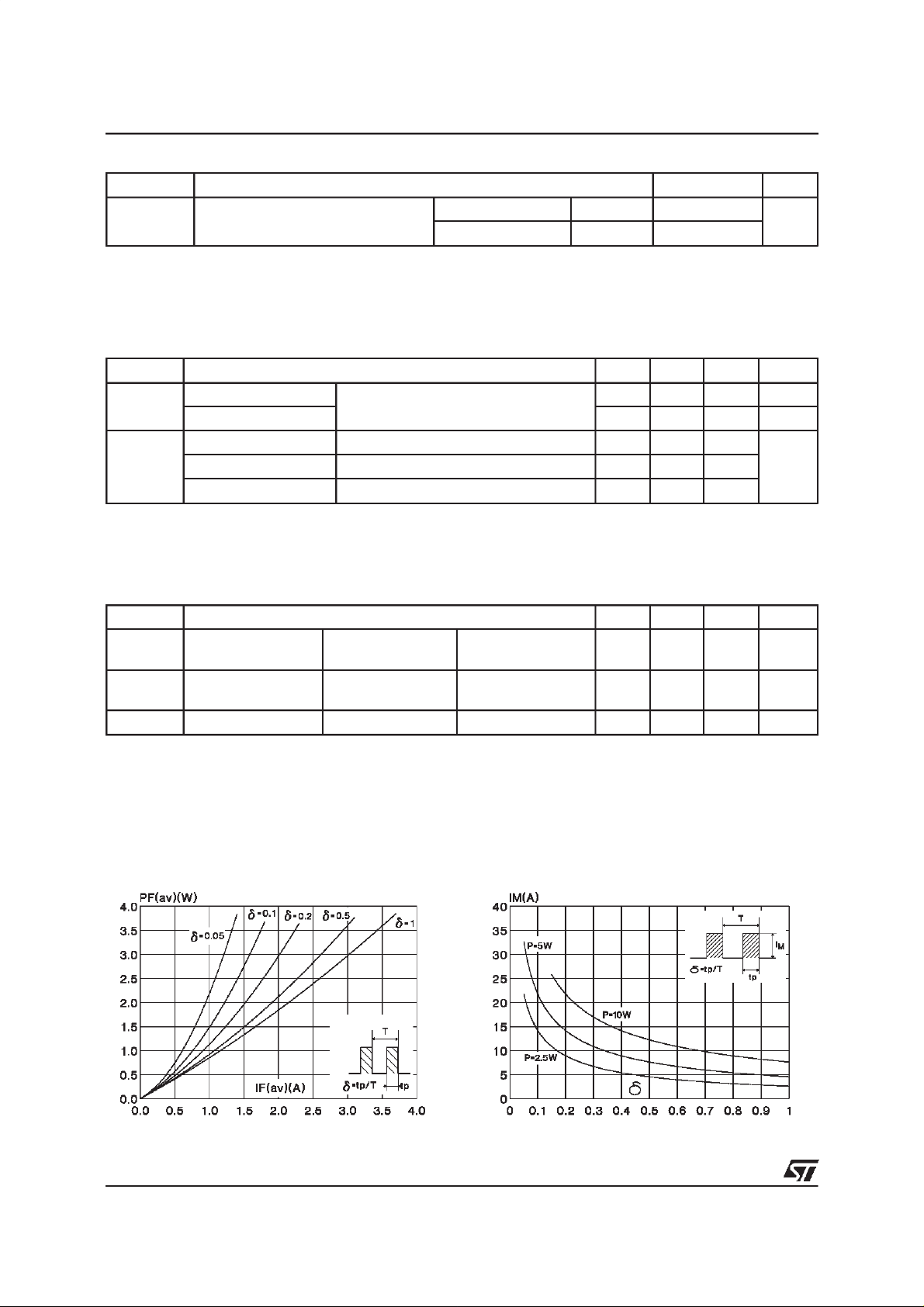
To evaluatethe conductionlossesuse thefollowingequation:
P = 0.78x I
Fig. 1:
Average forwardpower dissipation versus aver-
age forward current (Per diode).
F(AV)
+0.070x I
F2(RMS)
Fig. 2:
Peak current versus form factor.(Perdiode)
2/6
Page 3

STPR620CT/STPR620CF
Fig. 3:
Average currentversus ambienttemperature.
(duty cycle : 0.5) (TO220AB)
Fig. 5:
Non repetitive surgepeak forward currentversus
overload duration
(Maximum values) (Per diode) (TO220AB).
Fig. 4:
Averagecurrent versus ambient temperature.
(duty cycle : 0.5) (ISOWATT220AB)
Fig. 6:
Non repetitive surgepeak forward currentversus
overload duration
(Maximum values) (Per diode) (ISOWATT220AB).
Fig. 7: Relative variation of thermal transient impedance
junction to case versus pulse duration
(Per diode) (TO220AB).
Fig. 8: Relative variation of thermal transient impedance
junction to case versus pulse duration
(Per diode) (ISOWATT220AB).
3/6
Page 4

STPR620CT/STPR620CF
Fig. 9:
Forward voltage drop versus forward current.
(maximum values) (Per diode).
Fig. 11:
Recovery charges versus dI
/dt (Per diode).
F
Fig. 10:
plied (Typical values) (Per diode).
Fig. 12:
Junctioncapacitance versusreverse voltage ap-
Peakreverse current versus dIF/dt (Per diode).
Fig. 13: Dynamic parameters versusjunction temperature (Per diode).
4/6
Page 5
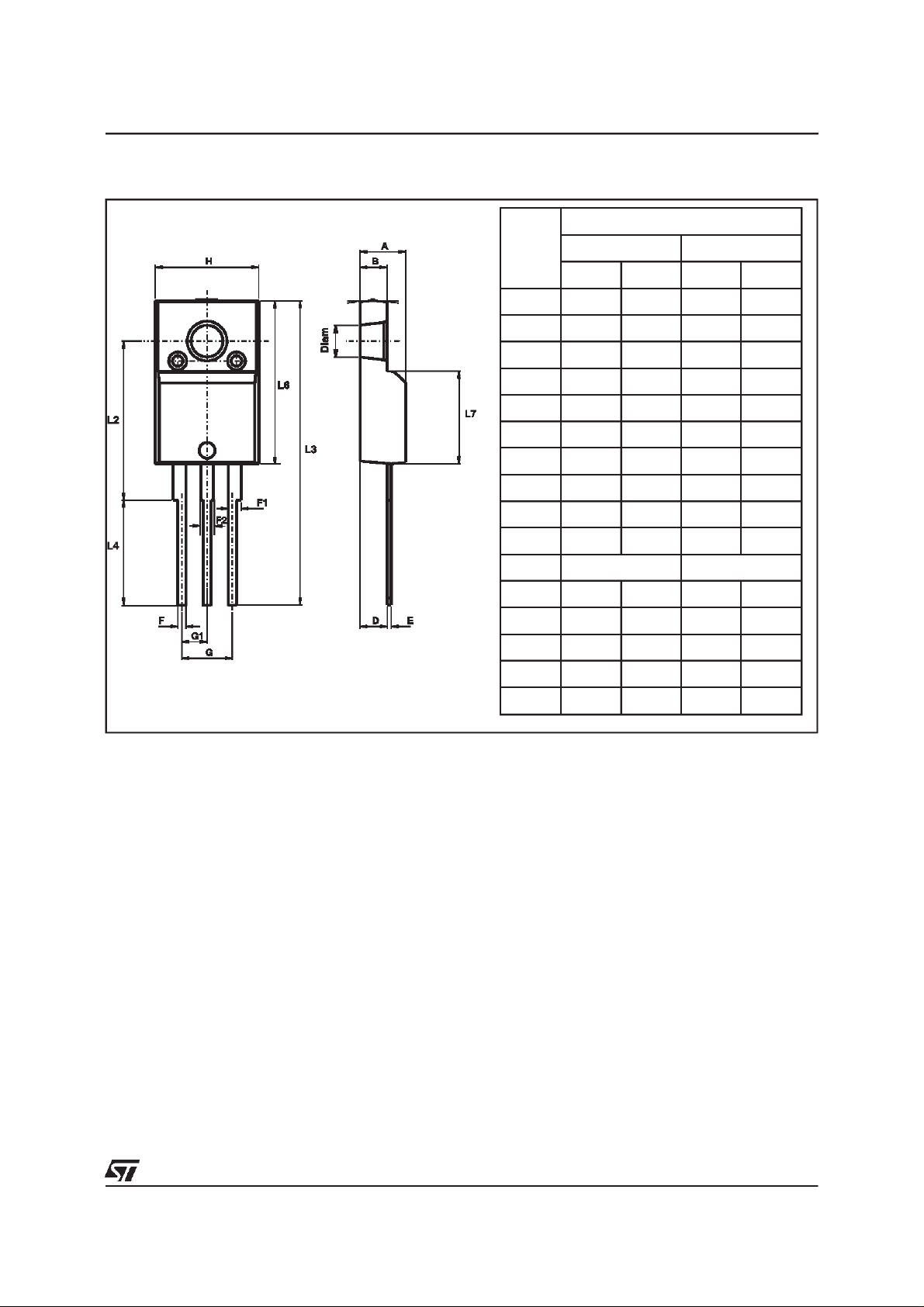
PACKAGEMECHANICALDATA
ISOWATT220AB(JEDEC outline)
STPR620CT/STPR620CF
DIMENSIONS
REF.
A 4.40 4.60 0.173 0.181
B 2.50 2.70 0.098 0.106
D 2.50 2.75 0.098 0.108
E 0.40 0.70 0.016 0.028
F 0.75 1.00 0.030 0.039
F1 1.15 1.70 0.045 0.067
F2 1.15 1.70 0.045 0.067
G 4.95 5.20 0.195 0.205
G1 2.40 2.70 0.094 0.106
H 10.00 10.40 0.394 0.409
L2 16.00typ. 0.630typ.
L3 28.60 30.60 1.125 1.205
Millimeters Inches
Min. Max. Min. Max.
Coolingmethod : C
Marking: Type number
Weight: 2.08g
L4 9.80 10.60 0.386 0.417
L6 15.90 16.40 0.626 0.646
L7 9.00 9.30 0.354 0.366
Diam 3.00 3.20 0.118 0.126
Recommendedtorque value : 0.55m.N
Maximumtorque value: 0.70m.N
5/6
Page 6

STPR620CT/STPR620CF
PACKAGEMECHANICAL DATA
TO220AB(JEDEC outline)
H2
Dia
L5
L6
L2
F2
F1
F
G1
G
L9
L4
DIMENSIONS
REF.
Millimeters Inches
Min. Max. Min. Max.
A 4.40 4.60 0.173 0.181
A
C
L7
C 1.23 1.32 0.048 0.051
D 2.40 2.72 0.094 0.107
E 0.49 0.70 0.019 0.027
F 0.61 0.88 0.024 0.034
F1 1.14 1.70 0.044 0.066
F2 1.14 1.70 0.044 0.066
G 4.95 5.15 0.194 0.202
D
G1 2.40 2.70 0.094 0.106
H2 10 10.40 0.393 0.409
L2 16.4 typ. 0.645 typ.
M
E
L4 13 14 0.511 0.551
L5 2.65 2.95 0.104 0.116
L6 15.25 15.75 0.600 0.620
L7 6.20 6.60 0.244 0.259
L9 3.50 3.93 0.137 0.154
M 2.6 typ. 0.102 typ.
Diam. 3.75 3.85 0.147 0.151
Coolingmethod : C
Marking: Type number
Recommendedtorque value : 0.8m.N
Maximumtorque value: 1.0m.N
Weight: 2.23g
Informationfurnished isbelieved to be accurate and reliable. However, STMicroelectronics assumesno responsibilityfor the consequences of
use of such informationnor forany infringementof patentsor other rights of thirdparties which mayresult from its use. Nolicense isgranted by
implication or otherwise under any patent or patent rights of STMicroelectronics. Specifications mentioned in this publication are subject to
change without notice. This publication supersedes and replaces all information previously supplied.
STMicroelectronics products are not authorized for use as critical components in life support devices or systems without express written approval of STMicroelectronics.
The ST logo is a registered trademark of STMicroelectronics
1999 STMicroelectronics - Printed inItaly - All rights reserved.
STMicroelectronics GROUP OF COMPANIES
Australia - Brazil - China - Finland - France - Germany - Hong Kong - India - Italy- Japan - Malaysia
Malta - Morocco -Singapore - Spain - Sweden - Switzerland - United Kingdom - U.S.A.
http://www.st.com
6/6
 Loading...