


ULTRAFAST RECOVERY RECTIFIER DIODES
.SUITEDFOR SMPS
.LOWLOSSES
.LOWFORWARDAND REVERSE RECOVERY
TIME
.HIGHSURGECURRENTCAPABILITY
.HIGHAVALANCHE ENERGY CAPABILITY
STPR310D/F
STPR320D/F
A
K
DESCRIPTION
Low cost single chip rectifiersuited for switchmode
powersupplyandhighfrequency DCtoDCconverters.
Packaged in TO220AC and ISOWATT220AC, this
deviceis intended for use in low voltage, high frequency inverters, free wheeling andpolarity protection applications.
ABSOL UT E RATING S (limiting values)
Symbol Parameter Value Unit
I
F(RMS)
I
F(AV)
I
FSM
TstgTjStorage and Junction Temperature Range - 65 to +150
RMS ForwardCurrent 10 A
AverageForwardCurrent
δ =0.5
SurgeNon Repetitive Forward Current Tp = 10 ms
TO220AC Tc = 125°C3 A
ISOWATT220AC Tc = 120°C
TO2 20AC
(Plastic)
STPR310D
STPR320D
Sinusoidal
- 65 to +150
ISOWATT220AC
(Plastic)
STPR310F
STPR320F
30 A
K
A
°C
Symbol Parameter STPR Unit
310D
310F
V
RRM
TH ERMA L R ESIST A N CE
Symbol Paramete r Value Unit
Rth (j-c) Junction-case TO220AC 6.5 °C/W
February 1992 Ed: 1
Repetitive PeakReverse Voltage 100 200 V
ISOWATT220AC 8.5
320D
320F
1/6
STPR310D/F / STPR320D/F
ELECTRIC A L CHAR ACT ERI STIC S
STATIC CHARACTERISTICS
Symbol Tests Conditions Min. Typ. Max. Unit
IR*Tj=25°CV
Tj = 100°C 0.5 mA
=V
R
RRM
50 µA
VF** Tj = 125°CI
Tj = 125°CI
Tj = 25°CI
Pulse test : * tp = 5 ms, duty cycle < 2 %
** tp = 380 µs, duty cycle < 2%
= 3 A 0.99 V
F
= 6 A 1.20
F
= 6 A 1.25
F
RECOVERY CHARACTERISTICS
Symbol Tests Conditions Min. Typ. Max. Unit
trr Tj = 25°CI
tfr Tj = 25°CI
V
FP
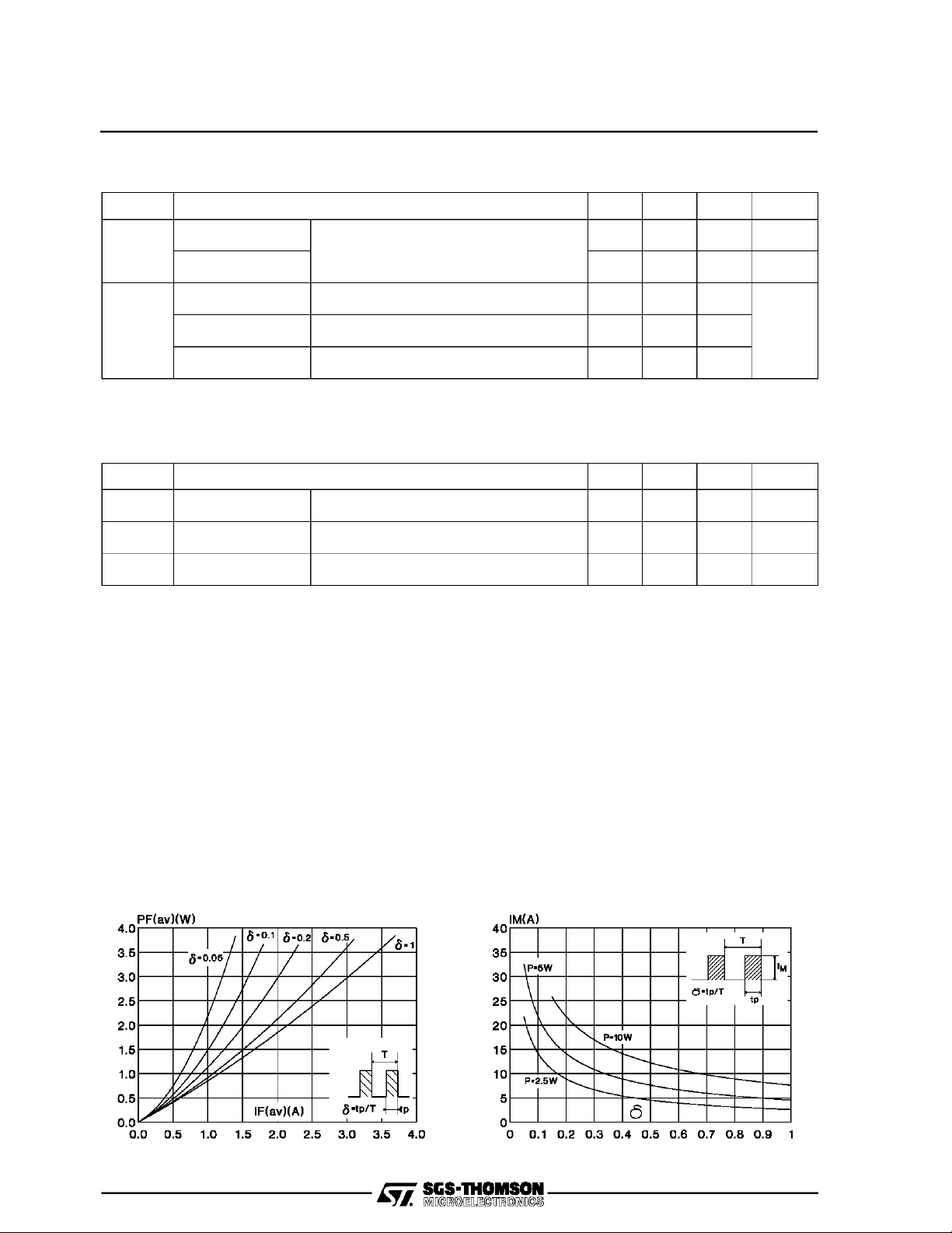
To evaluate the conduction losses use the following equation:
P = 0.78 x I
Tj = 25°CI
+ 0.070 I
F(AV)
F2(RMS)
= 0.5 A IR= 1A Irr=0.25 A 30 ns
F
= 1 A tr=10 ns VFR= 1.1x V
F
= 1 A tr=10 ns 3 V
F
F
20 ns
age forward current.
2/6
Fig.2 : Peak current versus form factor.Fig.1 : Average forward power dissipation versus aver-

STPR310D/F / STPR320D/F
Fig.3 : Average current versus ambient temperature.
(duty cycle : 0.5) (TO220AC)
Fig.5 : Non repetitive surge peak forward current versus
overload duration.
(Maximum values) (TO220AC)
Fig.4 : Average current versus ambient temperature.
(duty cycle : 0.5) (ISOWATT220AC)
Fig.6 : Non repetitive surge peak forward current versus
overload duration.
(Maximum values) (ISOWATT220AC)
Fig.7 : Relative variation of thermal transient impedance
junction to case versus pulse duration.
(TO220AC)
Fig.8 : Relative variation of thermal transient impedance
junction to case versus pulse duration.
(ISOWATT220AC)
3/6

STPR310D/F / STPR320D/F
Fig.9 : Forward voltage drop versus forward current.
(Maximum values)
Fig.11 : Recovery charge versus dIF/dt. Fig.12 : Peak reverse current versus dIF/dt.
Fig.10 : Junction capacitance versus reverse voltage
applied. (Typical values)
Fig.13 : Dynamic parameters versus junction temperature.
4/6

PACKAGE MECHANICAL DATA
TO220AC (JEDEC outline)
A
I
P
N
G
D
E
F
O
STPR310D/F / STPR320D/F
DIMENSIONS
H
J
REF.
A 10 10.4 0.393 0.409
B 15.2 15.9 0.598 0.626
C 13 14 0.511 0.551
K
B
D 6.2 6.6 0.244 0.260
E 16.4 typ. 0.645 typ.
F 3.5 4.2 0.137 0.165
G 2.65 2.95 0.104 0.116
H 4.4 4.6 0.173 0.181
L
C
I 3.75 3.85 0.147 0.151
J 1.23 1.32 0.048 0.051
K 1.27 typ. 0.050 typ.
L 0.49 0.70 0.019 0.027
M
M 2.4 2.72 0.094 0.107
N 4.95 5.15 0.194 0.203
O 1.14 1.70 0.044 0.067
P 0.61 0.88 0.024 0.034
Millimeters Inches
Min. Max. Min. Max.
Cooling method : C
Marking : Type number
Weight : 1.9 g
Recommended torque value : 0.55m.N
Maximum torque value : 0.7m.N
PACKAGE MECHANICALDATA
ISOWATT220AC (JEDECoutline)
A
I
B
D
C
O
P
N
H
J
REF.
Millimeters Inches
DIMENSIONS
Min. Max. Min. Max.
A 10 10.4 0.393 0.409
B 15.9 16.4 0.626 0.645
C 28.6 30.6 1.126 1.204
E
L
M
D 16 typ 0.630 typ
E 9 9.3 0.354 0.366
H 4.4 4.6 0.173 0.181
I 3 3.2 0.118 0.126
J 2.5 2.7 0.098 0.106
L 0.4 0.7 0.015 0.027
M 2.4 2.75 0.094 0.108
N 4.95 5.2 0.195 0.204
O 1.15 1.7 0.045 0.067
P 0.75 1 0.030 0.039
Cooling method : C
Marking : Type number
Weight : 2 g
Recommended torque value : 0.55m.N
Maximum torque value: 0.70m.N
Electrical Isolation : 2000V DC
Capacitance : 12pF
5/6

STPR310D/F / STPR320D/F
Information furnished is believed to be accurate and reliable. However, SGS-THOMSON Microelectronics assumes no responsability for the
consequences of useof such information nor forany infringementof patents or other rightsof thirdparties which may resultsfrom itsuse. No
license isgranted byimplication orotherwise underany patentor patent rights ofSGS-THOMSON Microelectronics. Specifications mentioned
in this publication aresubject to change without notice. Thispublication supersedes and replaces all information previously supplied.
SGS-THOMSON Microelectronicsproducts arenot authorized for useascritical componentsinlifesupport devicesorsystems withoutexpress
written approvalof SGS-THOMSONMicroelectonics.
1994 SGS-THOMSON Microelectronics - All Rights Reserved
TURBOSWITCH, TRANSIL, TRISIL, SNUBBERLESS are Trademarks of SGS-THOMSON Microelectronics.
Australia - Brazil - France - Germany- Hong Kong - Italy - Japan - Korea - Malaysia - Malta - Morocco- The Netherlands -
Singapore - Spain - Sweden - Switzerland - Taiwan - Thailand - United Kingdom - U.S.A
SGS-THOMSON MicroelectronicsGROUP OF COMPANIES
6/6
 Loading...