

ON CHIP POLARITYGUARD
MEETS DC LINE CHARACTERISTICS OF
EITHER CCITTANDEIARS464SPECS
PULSE FUNCTION
HIGHAC IMPEDANCE
OFFHOOK-STATUS DETECTION OUTPUT
LOW EXTERNAL COMPONENT COUNT
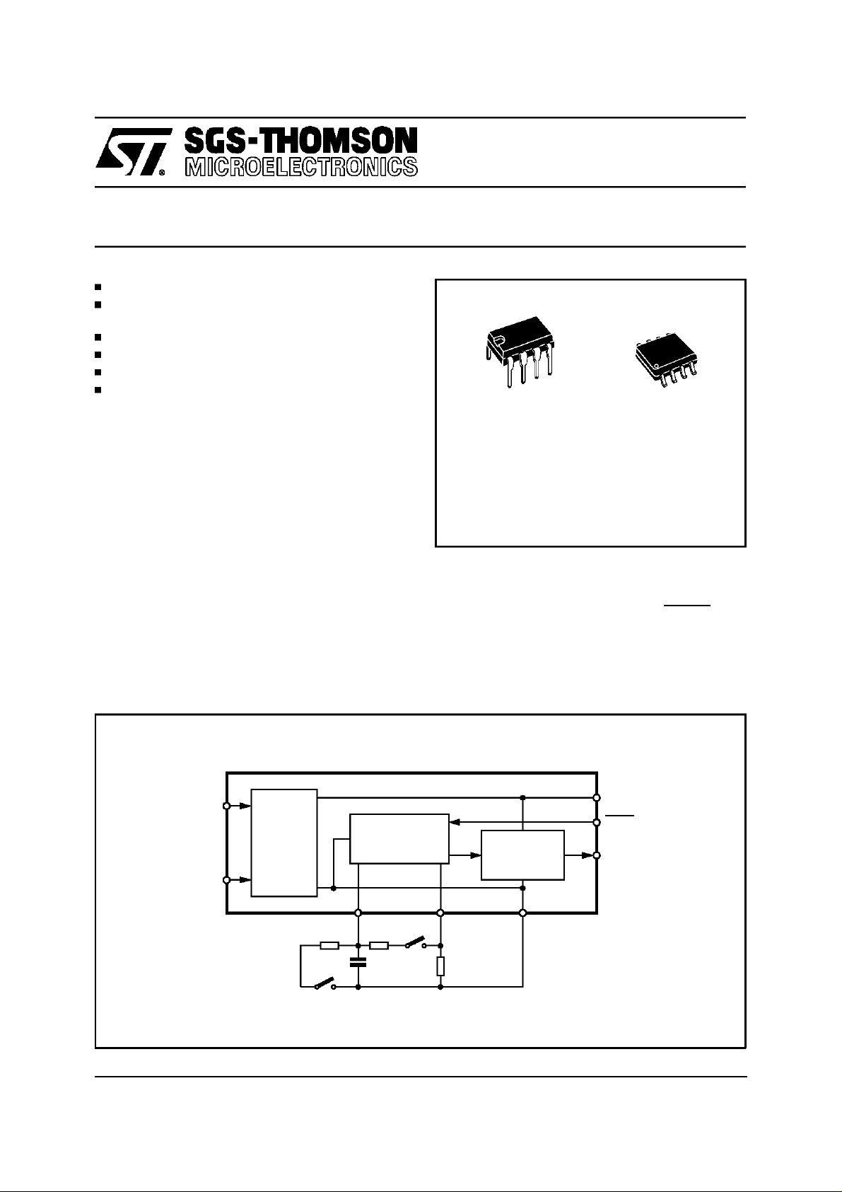
DESCRIPTION
The circuit provides DC loop termination for analog trunk lines.
The V-I characteristics is equivalent to a fixed
voltage drop (zener like characteristic) in series
with an external resistance that determines the
slope of the DC characteristic.
An external low voltage electrolytic capacitor
causes the circuit to exhibit a very high impedance to all AC signal above a minimum frequency
that is determinedby the capacitor itselfand by a
20 Knominalresistor integrated on thechip.
The Off-Hook status is detected all the time a
typic of 8 mA is flowinginto thecircuit. In this condition a constant current generator is activated to
L3845
TRUNK INTERFACE
Minidip SO8
ORDERING NUMBERS:
L3845B L3845D
supply an external device (typically an optocoupler) without affectingthe AC characteristicof the
circuit.
When Pulse Dialing is required the PULSE input
(pin 3) connected to V- causes the device to reduce the fixed DC voltage drop and to exhibit a
pure resistive impedanceequal to the externalresistor.
BLOCK DIAGRAM
8
1
IN1
DC
POLARITY
GUARD
7
IN2
562
ACT DCT V-
R2 R3
S1
June 1996
This is advanced information on a new product now in development or undergoing evaluation. Details are subject to change without notice.
LINE
TERMINATION OF
S2
C1
R1
DETECTION
HOOK
CIRCUIT
D96TL263
V+
3
PULSE
4
HD0
1/7
L3845
ABSOLUTE MAXIMUM RATINGS
Symbol Parameter Value Unit
V
L
I
L
P
tot
T
op
T
srg,Tj
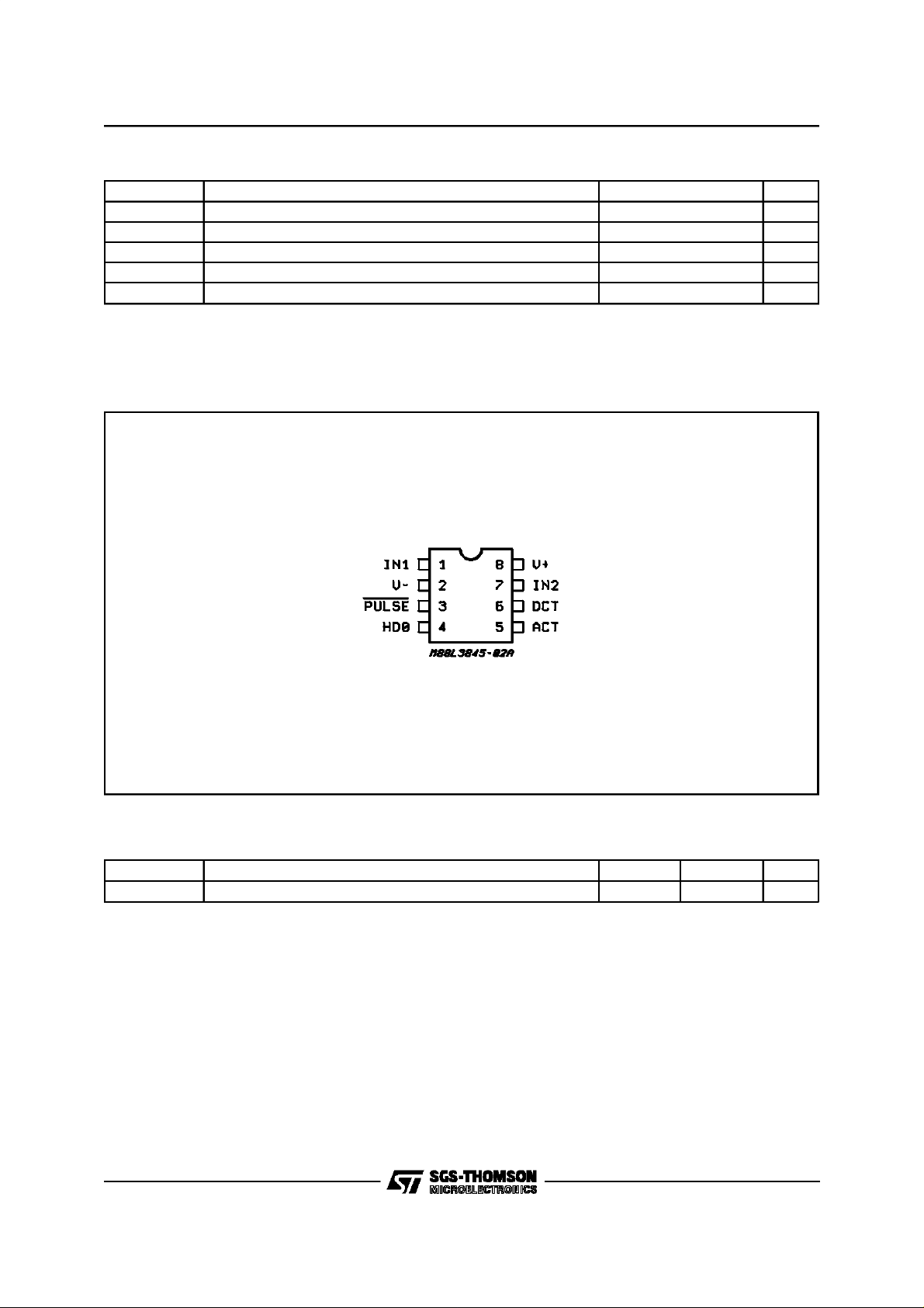
PIN CONNECTION (Topview)
Max Line Voltage (pulse duration 10 ms max) 20 V
Max Line Current 150 mA
Total Power Dissipation at Tamb = 70 °C 800 mW
Operating Temperature – 40 to + 70 °C
Storage and Junction Temperature – 55 to + 150 °C
THERMAL DATA
Symbol Parameter Minidip SO8 Unit
R
th j-amb
(*) Mounted on FR4 Boards
2/7
Thermal Resistance Junction-ambient (*) Max. 80 140 to 180°C/W

L3845
DC ELECTRICALCHARACTERISTICS
= 10 mA to 100 mA, R1=56Ω,S1= Open, T
(I
L
=+25°C,
amb
unless otherwisespecified)
Symbol Parameter Test Condition Min. Typ. Max. Unit
V
L
Line Voltage
(normal mode)
V
LP
Line Voltage
(pulse mode)
I
hn
ON/OFF-Hook
Line CurrentDetection
Threshold
I
hf
OFF/ON-Hook
Line CurrentDetection
Threshold
I
OUT
OFF-Hook
Output Drive Current at Pin
HDO
V
PM
I
PM
Pulse Input Low Voltage 0.8 V
Pull-up Input Current at Pin
PULSE (pulse mode)
I
NM
Imput Current at Pin Pulse
(normal mode)
PULSE = Open
IL = 10 mA
I
=20mA
L
I
= 100 mA
L
PULSE = V
–
IL=20mA
I
=35mA
L
I
=80mA
L
IL = 10 mA
I
20 mA
≥
L
IL = 100 mA
Pulse = V
–
5
6
12
4
5.5
9.5
6.5 9.5 mA
59.2mA
1.5
2
20 µA
3
V
V
V
V
V
V
mA
mA
µ
A
AC ELECTRICALCHARACTERISTICS (IL= 10mAto 100mA, R1=56Ω,R2=470KΩ,R3= 130KΩ,
T
=+25°C, unless otherwise specified)
amb
Symbol Parameter Test Condition Min. Typ. Max. Unit
Z
L
(*) Not tested,guaranteed only by design.
APPLICATIONINFORMATION
With the use of this circuit it is possible to terminate an analog trunk so that all the DC current
component is flowing in the TRUNK TERMINATION CIRCUIT while the AC component is decoupled with a low voltage capacitor and can be
used with a small and low cost audio coupler
transformer to provide the AC balancing termination and two to four wire conversion.
Therefore it is usefull both for MODEMand PABX
systems.
AC Line Impedance S1= Open, S2= Open
C
= 2.2mF
1
f = 1KHz
Sending/Receiving Distortion S
= Open, S2= Open
1
f = 1KHz
V
= 775mVrms
AC-L
I
= 15 to 100mA
L
Sending/Receiving Distortion S
Sending/Receiving Distortion S
= Closed; S2= Open
1
V
= 1.3Vrms 2 %
AC-L
= Open; S2= Closed
1
V
= 1.9Vrms
AC-L
Figure 1 gives the typical application circuit ; it is
worth to note that the TRUNK TERMINATION
CIRCUIT,togetherwith the LS5018transient suppressor provides a compact and low cost module
fully protected against lightning or overvoltages
frequentlypresent on telephonelines.
The PULSE input when connected to V- allows
the device to reduce the Line Voltage and to
show a resistive impedance equal to R1 to the
line. When PULSEinput is left open, this function
is disable.
20 K
2%
2(*) %
Ω
3/7

L3845
Figure 1:
TypicalApplication.
4/7

MINIDIP PACKAGE MECHANICALDATA
L3845
DIM
Min. Typ. Max. Min. Typ. Max.
A 3.32 0.131
a1 0.51 0.020
B 1.15 1.65 0.045 0.065
b 0.356 0.55 0.014 0.022
b1 0.204 0.304 0.008 0.012
D 10.92 0.430
E 7.95 9.75 0.313 0.384
e 2.54 0.100
e3 7.62 0.300
e4 7.62 0.300
F 6.6 0260
i 5.08 0.200
L 3.18 3.81 0.125 0.150
Z 1.52 0.060
mm inch
5/7
L3845
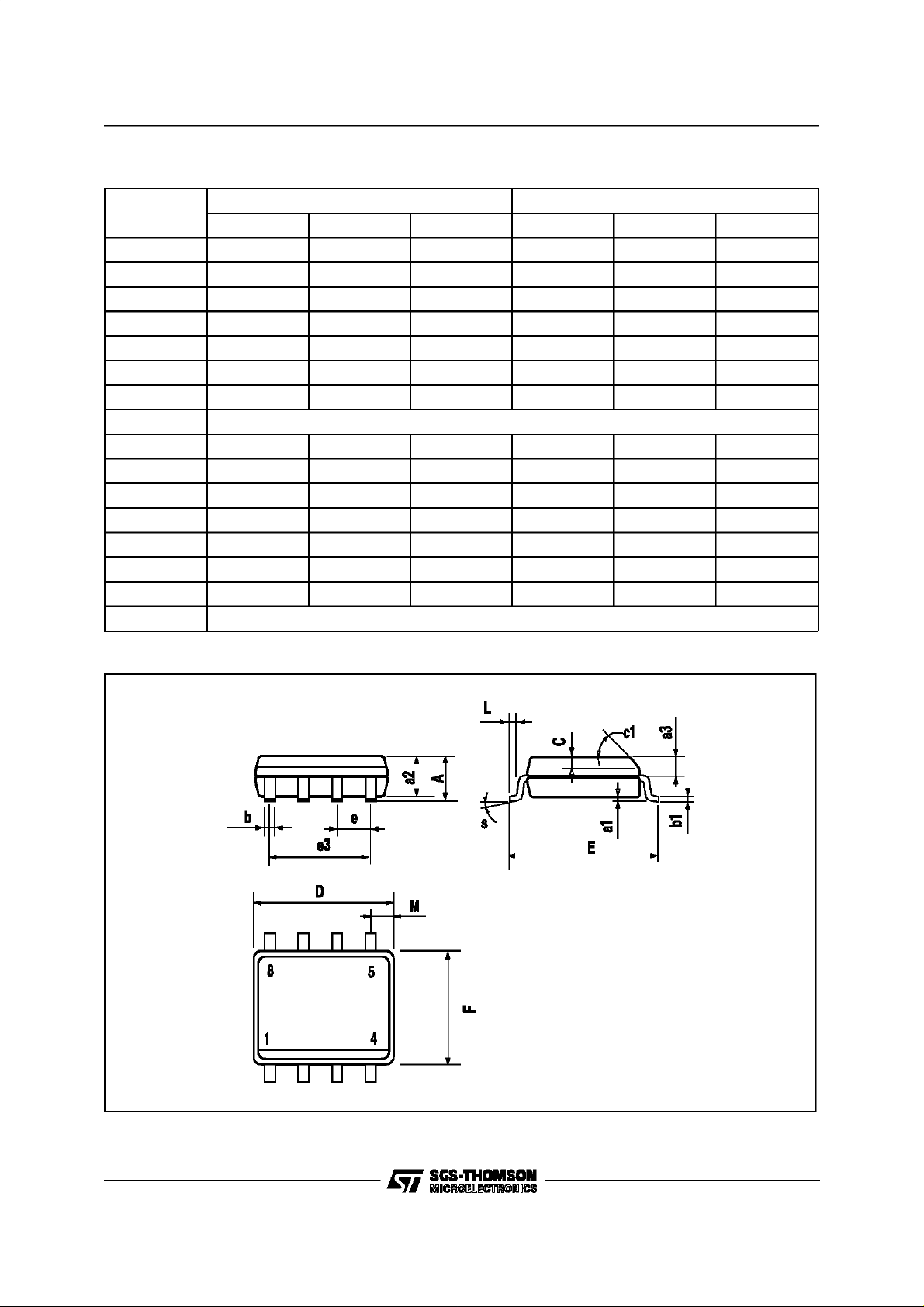
SO8 PACKAGE MECHANICAL DATA
DIM
mm inch
Min. Typ. Max. Min. Typ. Max.
A 1.75 0.069
a1 0.1 0.25 0.004 0.010
a2 1.65 0.065
a3 0.65 0.85 0.026 0.033
b 0.35 0.48 0.014 0.019
b1 0.19 0.25 0.007 0.010
C 0.25 0.5 0.010 0.020
o
c1 45
(typ.)
D 4.8 5.0 0.189 0.197
E 5.8 6.2 0.228 0.244
e 1.27 0.050
e3 3.81 0.150
F 3.8 4.0 0.150 0.157
L 0.4 1.27 0.016 0.050
M 0.6 0.024
o
S8
(max.)
6/7

L3845
Information furnished is believed to be accurate and reliable. However, SGS-THOMSON Microelectronics assumes no
responsibility for the consequences of use of such information nor for any infringement of patents orother rights of third
parties which may result from its use. No license isgranted by implication or otherwise under any patent or patent rights
of SGS-THOMSON Microelectronics. Specifications mentioned in this publication are subject to change without notice.
This publication supersedes and replaces all information previously supplied. SGS-THOMSON Microelectronics products are not authorized for use as critical components in life support devices or systems without express written approval ofSGS-THOMSON Microelectronics.
1994 SGS-THOMSON Microelectronics - All Rights Reserved
Australia - Brazil - France - Germany - Hong Kong - Italy - Japan - Korea - Malaysia - Malta - Morocco - The Nether-
Singapore -Spain - Sweden - Switzerland - Taiwan - Thaliand - United Kingdom - U.S.A.
SGS-THOMSON Microelectronics GROUP OF COMPANIES
lands
7/7
 Loading...