

Page 1
SELECTABLE ICE
SV/SVi-200/250 SCI
INSTALLATION & SERVICE GUIDE
Part Number 020001172
Manitowoc Beverage Equipment
2100 Future Drive Sellersburg, IN 47172-1868
Tel: 812.246.7000, 800.367.4233 Fax: 812.246.9922
www.manitowocbeverage.com
In accordance with our policy of continuous product development and
improvement, this information is subject to change at any time without notice.
August 10, 2007 REV2
Page 2

FOREWORD
Manitowoc Beverage Equipment (MBE) developed this manual as a reference guide for the owner/
operator, service agent, and installer of this equipment. Please read this manual before installation
or operation of the machine. A qualified service technician should perform installation and startup of this equipment, consult the
If you cannot correct the service problem, call your MBE Service Agent or Distributor. Always have your model and
serial number available when you call.
Your Service Agent___________________________________________________________________
Service Agent Telephone Number ______________________________________________________
Your Local MBE Distributor ___________________________________________________________
Distributor Telephone Number _________________________________________________________
Model Number ______________________________________________________________________
Serial Number _______________________________________________________________________
Installation Date _____________________________________________________________________
Troubleshooting Guide
within this manual for service assistance.
UNPACKING AND INSPECTION
Note: The unit was thoroughly inspected before leaving the factory. Any damage or irregularities should
be noted at the time of delivery.
WARRANTY INFORMATION
Consult your local MBE Distributor for terms and conditions of your warranty. Your warranty specifically
excludes all beverage valve brixing, general adjustments, cleaning, accessories and related servicing.
Your warranty card must be returned to Manitowoc Beverage Equipment to activate the warranty on this
equipment. If a warranty card is not returned, the warranty period can begin when the equipment leaves
the MBE factory.
No equipment may be returned to Manitowoc Beverage Equipment without a written Return Materials
Authorization (RMA). Equipment returned without an RMA will be refused at MBE’s dock and returned to
the sender at the sender’s expense.
Please contact your local MBE distributor for return procedures.
Page 3

TABLE OF CONTENTS
FOREWORD ........................................................................................................ 2
UNPACKING AND INSPECTION ......................................................................... 2
WARRANTY INFORMATION ............................................................................... 2
SAFETY ............................................................................................................... 4
IMPORTANT SAFETY INSTRUCTIONS ........................................................................... 4
CARBON DIOXIDE WARNING ......................................................................................... 4
QUALIFIED SERVICE PERSONNEL ................................................................................ 4
SHIPPING, STORAGE, AND RELOCATION ..................................................................... 4
ADDITIONAL WARNINGS ................................................................................................ 4
GROUNDING INSTRUCTIONS ........................................................................................ 5
SELECTABLE ICE MODULE ............................................................................................ 6
INSTALLATION .................................................................................................... 6
OPERATION ........................................................................................................ 7
SELECTABLE ICE DISPENSING ..................................................................................... 7
RECOMMENDED ICE TYPES .......................................................................................... 7
SELECTABLE ICE CONTROL BOARD ............................................................................ 8
USER MAINTENANCE ........................................................................................ 9
HOW TO DISASSEMBLE FOR CLEANING OR MAINTENANCE .................................... 9
SELECTABLE ICE MODULE REMOVAL ......................................................................... 9
SELECTABLE ICE CRUSHER DISASSEMBLY................................................................ 9
HOW TO REASSEMBLE THE ICE CRUSHER ASSEMBLY ........................................... 10
CLEANING INSTRUCTIONS .......................................................................................... 12
TROUBLESHOOTING .................................................................................................... 13
EXPLODED VIEWS, PARTS & DIAGRAMS ..................................................... 14
SELECTABLE ICE 115V WIRING ................................................................................... 14
SELECTABLE ICE EXPLODED VIEW ............................................................................ 15
SELECTABLE ICE MODULE EXPLODED VIEW ............................................................ 16
SELECTABLE ICE MOTOR EXPLODED VIEW .............................................................. 17
REMOTE BOX ASSEMBLY ............................................................................................ 18
FLAVOR MAGIC/SELECTABLE ICE MODULE .............................................................. 19
INDEX................................................................................................................. 23
Page 4
SAFETY
IMPORTANT SAFETY INSTRUCTIONS
Carefully read all safety messages in this manual. Learn how to operate the Selectable Ice unit
properly. Do not allow anyone to operate the unit without proper training and keep it in proper
working condition. Unauthorized modifications to the Selectable Ice may impair function and/or
safety and affect the life of the unit.
CARBON DIOXIDE WARNING
DANGER: Carbon Dioxide (CO2) displaces oxygen. Exposure to a high concentration of CO2 gas
causes tremors, which are followed rapidly by loss of consciousness and suffocation. If a CO2 gas leak
is suspected, particularly in a small area, immediately ventilate the area before repairing the leak. CO
lines and pumps should not be installed in an enclosed space. An enclosed space can be a cooler or
small room or closet. This may include convenience stores with glass door self serve coolers. If you
suspect CO2 may build up in an area, venting of the B-I-B pumps and / or CO2 monitors should be utilized.
QUALIFIED SERVICE PERSONNEL
WARNING: Only trained and certified electrical and plumbing technicians should service this unit.
All wiring and plumbing must conform to national and local codes.
2
SHIPPING, STORAGE, AND RELOCATION
CAUTION: Before shipping, storing, or relocating this unit, syrup systems must be sanitized. After
sanitizing, all liquids (sanitizing solution and water) must be purged from the unit. A freezing environment causes residual sanitizing solution or water remaining inside the unit to freeze, resulting
in damage to internal components.
ADDITIONAL WARNINGS
Installation and start-up of this equipment should be done by a qualified service technician. Operation,
maintenance, and cleaning information in this manual are provided for the user/operator of the equipment.
Save these instructions.
Page 5

Installation and Service Manual
SAFETY
GROUNDING INSTRUCTIONS
WARNING: Risk of electrical shock. Connect to a properly grounded outlet only.
This appliance must be grounded. In the event of malfunction or breakdown, grounding provides
a path of least resistance for electric current to reduce the risk of electric shock. This appliance is
equipped with a cord having an equipment-grounding conductor and a grounding plug. The plug
must be plugged into an appropriate outlet that is properly installed and grounded in accordance
with all local codes and ordinances.
DANGER – Improper connection of the equipment-grounding conductor can result in a risk of
electric shock. The conductor with insulation having an outer surface that is green with or without
yellow stripes is the equipment grounding conductor. If repair or replacement of the cord or plug
is necessary, do not connect the equipment-grounding conductor to a live terminal. Check with a
qualified electrician or serviceman if the grounding instructions are not completely understood, or
if in doubt as to whether the appliance is properly grounded. Do not modify the plug provided with
the appliance – if it will not fit the outlet, have a proper outlet installed by a qualified electrician.
WARNING – When using electric appliances, basic precautions should always be followed, including the following:
a)Read all the instructions before using the appliance.
b)To reduce the risk of injury, close supervision is necessary when an appliance is used
near children.
c) Do not contact moving parts.
d)Only use attachments recommended or sold by the manufacturer.
e)Do not use outdoors.
f) For a cord-connected appliance, the following shall be included:
• Do not unplug by pulling on cord. To unplug, grasp the plug, not the cord.
• Unplug from outlet when not in use and before servicing or cleaning.
• Do not operate any appliance with a damaged cord or plug, or after the appliance
malfunctions or is dropped or damaged in any manner. Return appliance to the
nearest authorized service facility for examination, repair, or electrical or mechanical
adjustment.
g)For a permanently connected appliance – Turn the power switch to the off position when
the appliance is not in use and before servicing or cleaning.
h)For an appliance with a replaceable lamp – always unplug before replacing the lamp.
Replace the bulb with the same type.
i) For a grounded appliance – Connect to a properly grounded outlet only. See Grounding
Instructions.
SAVE THESE INSTRUCTIONS
5
Page 6
Installation and Service Manual
INSTALLATION
Please read installation section of the SV
Series Installation & Service Manual
to become familiar with the requirements to install an SV dispenser. The Selectable Ice dispensing system is mated to SV-200 and SV-250 model ice
and beverage Dispensers only.
SELECTABLE ICE MODULE
The Selectable Ice Module will not be installed on the
dispenser when unit is unboxed.
1. Locate the Selectable Ice Module box in the dispenser
bin and remove the module from the box.
2. Remove merchandiser from dispenser by taking out
the two screws located at the top of the merchandiser.
Once the screws are removed rotate the top of the
SLOTTED SCREWS
Figure 1
Figure 2
merchandiser towards you and then lift the merchandiser up to remove from unit.
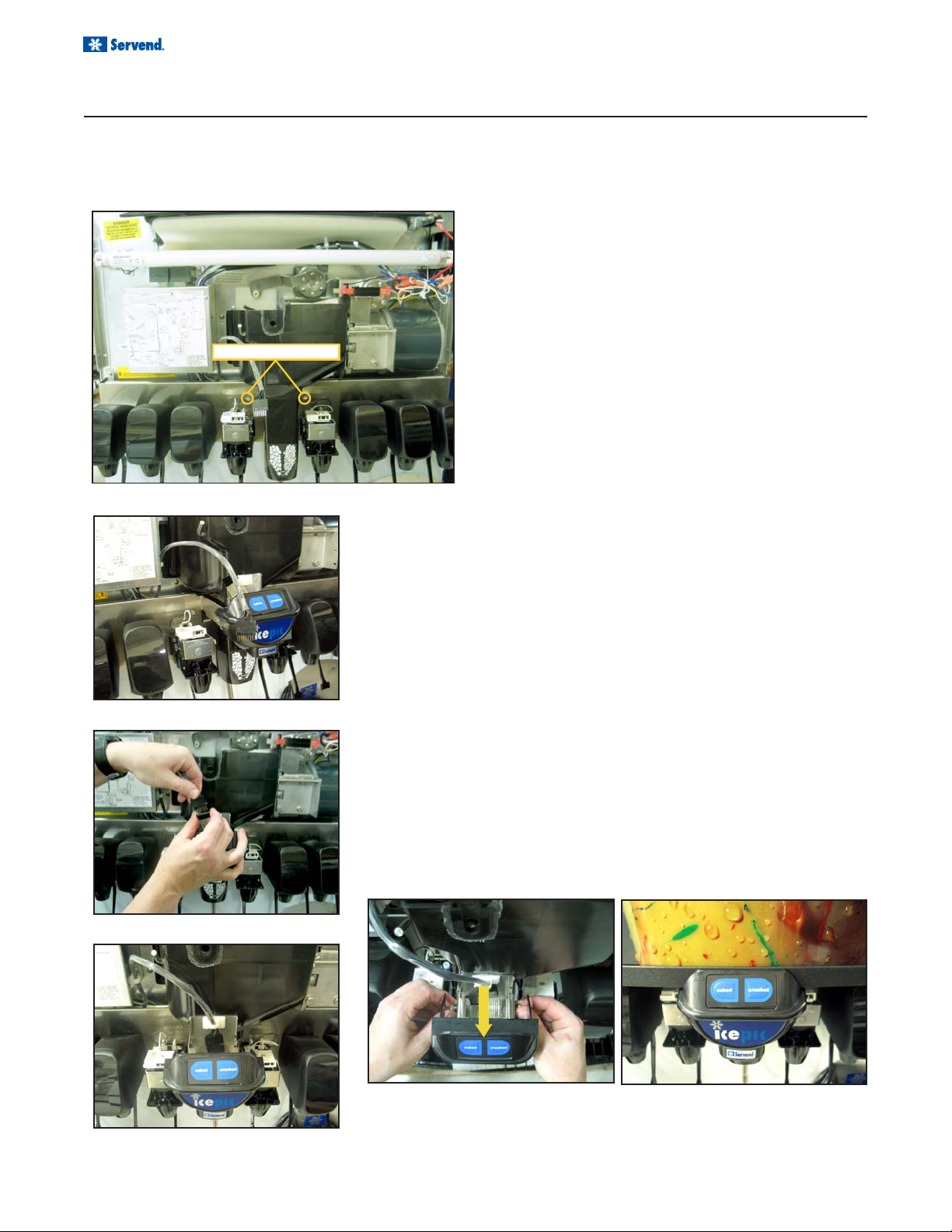
3. Remove the valve covers from the two valves next to
the rocking chute. (See Figure 1)
4. Loosen the two slotted knurl screws located on the
valve mount cap. (See Figure 1)
5. Hang the Selectable Ice Module bracket over the valve
mount cap, and secure to the valve mount cap by tightening the knurl screws. (See Figure 2)
6. Connect the wiring harness to the Selectable Ice Module (Figure 3) and locate the wire harness in the plastic
clip as seen in figure 4.
7. Loosen the bracket adjustment screws and pull the
module toward you. This will allow for reinstallation of
the merchandiser. (See Figure 5)
8. Install merchandiser and adjust the Selectable Ice Module so that it is flush with the front of the merchandiser.
Tighten the adjustment screws. (See Figure 6)
If the equipment being installed has the Flavor Magic
option, follow the instructions on pages 7, 10, and 11 in
Flavor Magic manual 020001309 for installation of the
front module and the remote box. Also use manual
020001309 for programming and trouble shooting the
Flavor Magic portion of this equipment.
An exploded view and parts list for the Flavor Magic/
Selectable Ice module and Remote box are included in
the EXPLODED VIEWS, PARTS, AND DIAGRAMS
section of this manual.
Figure 3
Figure 5
Figure 4
Figure 6
6
Page 7
Installation and Service Manual
OPERATION
SELECTABLE ICE DISPENSING
The first step of selectable ice dispensing is selecting the type ice to be dispensed (Cubed or Crushed). To select the
type ice to be dispensed, press the Cubed or Crushed selection on the key pad located on the front of the dispenser.
Once a type of ice is selected the dispenser will default to that type ice until the other type ice is selected.
Crushed Ice Sequence of Operation:
The customer presses the decorative ice chute and the
microswitch initiates the crushed ice dispensing process.
When activated, the microswitch energizes a solenoid
that opens the ice crusher housing door. The micro switch
also starts the gear motor and ice crusher motor. The
gear motor turns the paddle wheel and U-bar agitator.
The paddle wheel carries ice to the crusher assembly.
Once the ice reaches the crusher housing, four stationary blades and three rotating blades crush the ice and
push it through the opening in the ice crusher housing.
The crushed ice then falls through the opening into the
decorative ice chute, and into the customer’s cup.
Cubed Ice Sequence of Operation:
The customer presses the decorative ice chute and the
microswitch initiates the cube ice dispensing process.
When activated, the microswitch energizes a solenoid
that opens the cube ice dispense door, and the agitator
motor starts. The agitator motor turns the paddle wheel
and U-bar agitator. The paddle wheel carries ice to the
cubed ice dispense point. The ice then falls through the
opening into the decorative ice chute, and into the
customer’s cup.
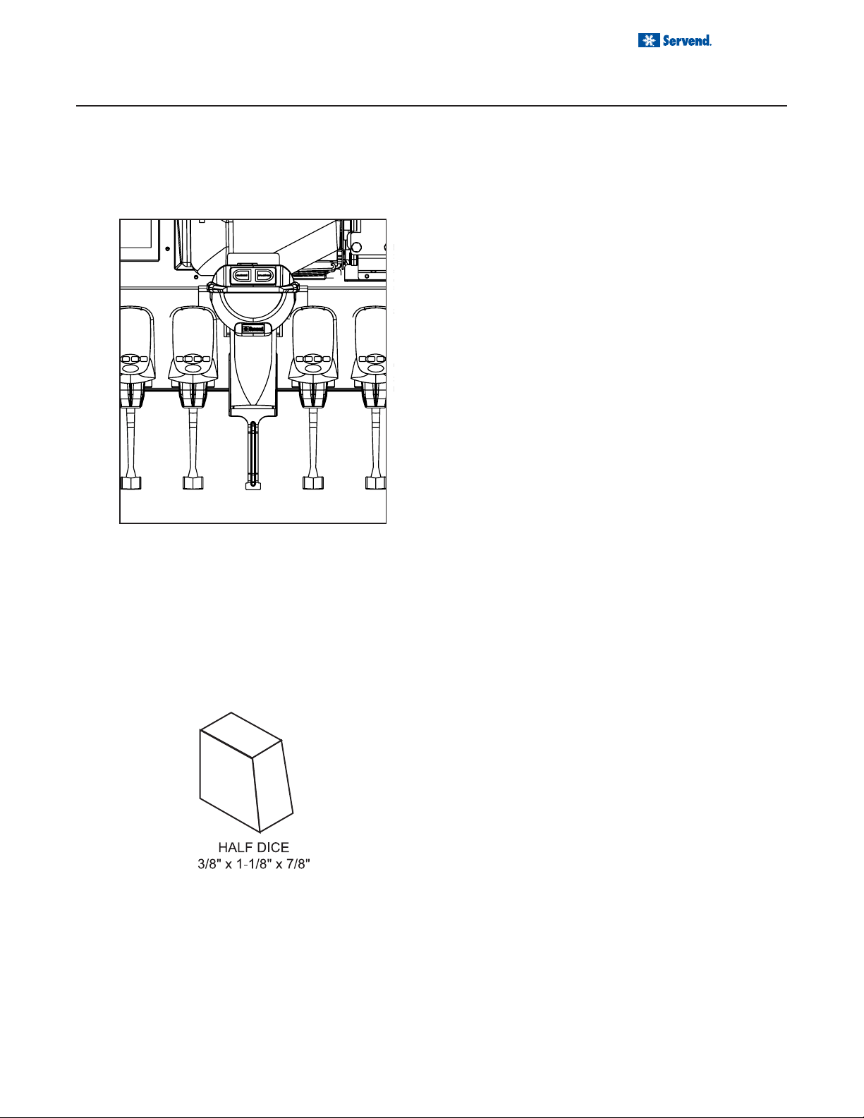
RECOMMENDED ICE TYPES
Manitowoc Half Dice Ice has been shown to give the
best performance in this dispenser. Hoshizaki America,
Inc., ice machines with crescent-style shape cubes are
not compatible with this dispenser.
Super-cooled ice is ice that has been stored below 32o F
(0o C). Super-cooled ice should be allowed to warm at
room temperature for 25 to 30 minutes before emptying
into the dispenser. Failure to do so may result in severe
damage to the dispenser.
7
Page 8
Installation and Service Manual
OPERATION
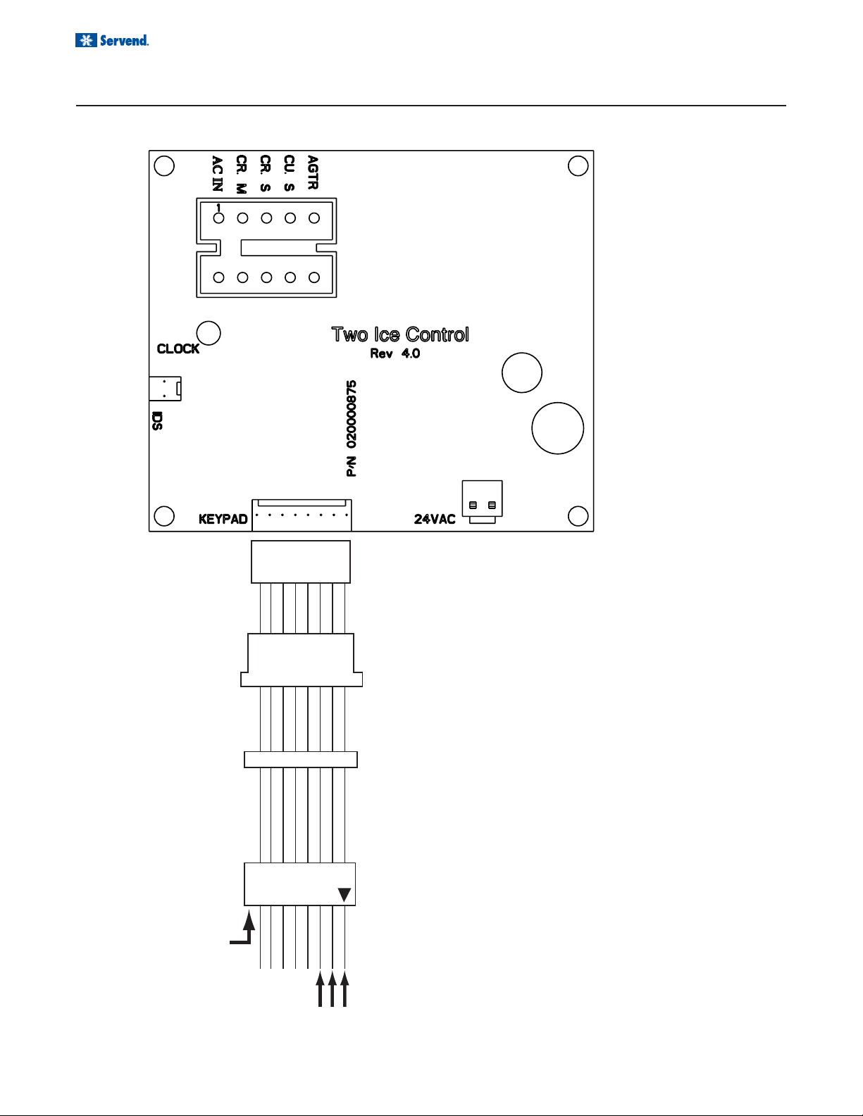
SELECTABLE ICE CONTROL BOARD
No Pin
Triangle on the harness indicates pin 1 location, pin 9
location is blank.
Continuity between pin 1&2 = cubed ice
Continuity between pin 1&3 = crushed ice
9
Pin Locations
8
321
Page 9

Installation and Service Manual
USER MAINTENANCE
HOW TO DISASSEMBLE FOR CLEANING OR MAINTENANCE
See cleaning section of the SV
COTTER PIN
Series User, Installation & Service Manual
bin and other components of the SV unit.
Before servicing or cleaning any part of the Selectable
Ice unit be sure to unplug it from its power source. In order to access the module and crusher you must first remove the merchandiser by taking out the two screws located at the top of the merchandiser. Once the screws
are removed, rotate the top of the merchandiser towards
you and then lift the merchandiser up to remove from unit.
Selectable Ice Module Removal
1. Loosen knurled screws.
2. Disconnect housing bracket
Selectable Ice Crusher Disassembly
1. Unplug unit before cleaning or servicing the Crusher
Assembly.
2. Remove the merchandiser by taking out the two
screws located at the top of the merchandiser. Once
the screws are removed rotate the top of the merchandiser towards you and then lift the merchandiser
up to remove from unit.
for cleaning procedures involving the
SOLENOID
ARM
HOUSING
DOOR
DRIP PAN
CHUTE ROD
DECORATIVE
CHUTE
Note: When the Merchandiser is removed an elec-
trical safety switch disconnects power to the
Ice Crusher assembly.
3. Remove the Ice Chute by pulling the cotter pin out
on the right side of the chute rod and pulling the
chute rod toward the left side of the dispenser.
4. Remove the crushed ice and cube ice doors from
the dispenser by lifting the solenoid arms up and
pushing the doors back to disengage the door from
the solenoid arms.
5. Remove the Crusher Drip Pan by pulling it forward.
MOTOR MOUNT
HOUSING MOUNT
9
Page 10

Installation and Service Manual
HOW TO DISASSEMBLE FOR CLEANING OR MAINTENANCE
CRUSHER HOUSING
LOCKING TAB
HUB/BLADE
ASSEMBLY
CRUSHER HOUSING
USER MAINTENANCE
6. See the following steps to remove the ice crusher
blade assembly from the crusher housing.
A. Unlock the Crusher Hub/Blade assembly from
the Crusher Housing by pushing locking tab in,
and rotating the Hub/Blade assembly clockwise.
B. Pull the Hub/Blade assembly out of the hous-
ing approx. ½” to disengage the Crusher Axle
from the motor shaft.
C. Rotate the knob on the Crusher Axle so it is in a
vertical position. (This will assure the rotating
blades will not interfere with pulling the Hub/Blade
assembly from the housing.)
D. Now the Hub/Blade assembly will be free from
the housing and you will be able to completely
remove the Hub/Blade assembly from unit.
HUB/BLADE
ASSEMBLY
AXLE KNOB
HOW TO REASSEMBLE THE ICE CRUSHER ASSEMBLY
STATIONARY BLADES
AXLE KNOB
CRUSHER HOUSING
1. Insert the Hub/Blade assembly into the Ice Crusher
Housing. When inserting the Hub/Blade assembly you
must align the Stationary blades with the locating slots
in the Ice Crusher Housing.
2. When inserting the Hub/Blade assembly into the Ice
Crusher Housing you must also make sure the Axle
Knob is in a vertical position. This will align the rotating
blades with the Housing to assure a quick and easy
installation.
10
HUB/BLADE ASSEMBLY
Page 11

LOCKING TAB
HUB/BLADE
ASSEMBLY
Installation and Service Manual
USER MAINTENANCE
HOW TO REASSEMBLE THE ICE CRUSHER ASSEMBLY
3. Once all blades are in the Crusher Housing you will need
to align the Crusher Axle with the motor shaft. You can
do this by turning the Axle Knob and pushing the blade
assembly toward the motor until the Hub/Blade assembly is flush with the end of the Crusher Housing.
4. To lock the Hub/Blade assembly into the housing, rotate the Crusher Hub/Blade assembly counter clockwise until the locking tab snaps into place and the
Crusher Hub/Blade assembly is secure.
5. Replace the Crusher Drip Pan.
6. Reattach the Decorative Ice Chute by inserting the chute
rod through the Decorative Chute, Housing Mount, and
Motor Mount. Secure the Chute Rod by inserting the
cotter pin through the rod on the right side of the chute.
7. Ensure the extension at the top of the Decorative
Chute is behind the arm of the Activation Switch.
DRIP PAN
MOTOR MOUNT
HOUSING MOUNT
COTTER PIN
CHUTE ROD
DECORATIVE
CHUTE
11
Page 12

Installation and Service Manual
USER MAINTENANCE
CLEANING INSTRUCTIONS
Clean and sanitize unit according to the directions in the cleaning section of the
Manual
CRUSHER HOUSING
HUB/BLADE
ASSEMBLY
. Clean and sanitize the Selectable Ice components according to the following instructions.
1. Mix a solution of mild detergent to clean the Select-
HOUSING DOOR
DRIP PAN
DECORATIVE CHUTE
SANITARY LEVER
able Ice components. Using the detergent solution
and a soft bristle brush or clean cloth, clean the following components:
• Decorative Chute
• Housing
• Housing Door
• Sanitary Lever
• Hub/Blade Assembly
• Drip Pan
2. Rinse all parts in clean running water.
3. Mix a sanitizing solution of ¼ oz liquid, unscented
bleach (5.25% CL NaO concentration) for each gallon
of water. Mixture should provide 100 ppm available
chlorine.
4. Using the sanitizing solution, soft bristle brushes, or a
clean cloth, sanitize the components listed in step 1.
The ice storage chamber should be sanitized with a
soft bristle brush to adequately clean the metering
wheel slot and drainage area.
5. Reverse the procedure to reassemble the Selectable
Ice mechanism.
6. Reconnect power to unit.
7. Check for proper operation.
SV Installation & Service
12
Page 13

Installation and Service Manual
USER MAINTENANCE
TROUBLESHOOTING
This section is for troubleshooting the Selectable Ice dispensing system. Any problems with the base SV unit
should be diagnosed with Troublshooting section of the
PROBLEM POSSIBLE CAUSE CORRECTIVE ACTION
SV Series User, Installation & Service Manual
.
Dispenser does not
dispense crushed ice.
1) Nothing is heard.
2) Crusher motor hums but
does not turn.
3) Crusher dispense door
does not open.
4) Gear box on motor a. Gear box on motor faulty.
5) Crusher Motor turns but Gear
Motor for Paddlewheel/Agitator
Bar does not turn.
a. No power to dispenser
b. Loose wiring
c. Dispense switch faulty
d. Crusher Moto r Faulty.
e. Dispenser Safety Switch Open.
a. Blades obstructed.
b. Motor faulty
c. Faulty start relay/capacitor
a. Door sole noi d faulty
b. Loose wiring to solenoid
b. Crusher Axle broken
a. Agitator Gear Motor faulty.
b. Loose wiring.
a. Check power source and power cord.
b. Check wiring
c. Replace switch
d. Replace Motor/Gear Box
e. Assure Merchandiser is installed correctly
with the safety switch in the closed position.
a. Check for obstructions in ice crusher
housing.
b. Replace Motor
c. Check relay/capacitor and replace if bad.
a. Replace Solenoid
b. Check wiring
a. Replace Ice Crusher Motor Assembly
b. Replace Crusher Axle
a. Replace Agitator Gear Motor.
b. Check wiring
Nothing on dispenser
works.
Difficulty inserting
Blade/Hub Assembly into
Crusher housing
Crushed Ice dispenses
continuously, or by itself.
No flashing lights on
keypad, Fluorescent light
was on, crusher and
whole ice dispenser will
not function, transformer
breaker blown.
c. Obstruction in Ice bin stopping motor
a. No power to dispenser Check power source
b. Dispenser Safety Switch opens. Assure Merchandiser is installed correctly with
c. Loose wiring Check wiring.
a. Stationary Blades not aligned with
locating slots at top and bottom of
crushe r ho usi ng
b. Rotating Blades not in vertical
position.
c. Check for ice in Crusher Housing.
Ice Dispense Switch Faulty Replace the Ice dispense switch.
Water shorted out wiring harness on
valves only.
c. Check for obstruction.
the safety switch in the closed position.
See "How to Disassemble for Maintenance"
section in this manual.
Clean up water and reset transformer.
13
Page 14

Installation and Service Manual
EXPLODED VIEWS, PARTS & DIAGRAMS
SELECTABLE ICE 115V WIRING
Below are instructions for testing the timed agitation on the SI unit:
14
Page 15

Installation and Service Manual
EXPLODED VIEWS, PARTS & DIAGRAMS
SELECTABLE ICE EXPLODED VIEW
NO. Part# Description
1 00212539 STANDOFF 7/16 HIGH
2 1001005 STARTER LEV FS2
3 1001006 STARTER BASE
4 5008229 TRANSFORMER 75VA 120V W/BREAKER
5 5008644 BALLAST 115/60
6 5012374 CLIP HITCH PIN
7 5031408 BLADE / HUB
8 5031515 CAPACITOR CRUSHER
9 5031516 BRACKET CAPACITOR MTR ED-8110-1
10 5031518 RELAY MOTOR ED-8110-1
11 020000201 CAP CAPACITOR MOTOR
12 020000592 MERCH BOTTOM W/ LENS
13 020000867 PADDLE WHEEL AREA
14 020000874 DOOR WHOLE ICE
15 020000875 CONTROL BOARD 120V
16 020000879 DOOR CRUSHED ICE
17 020000914 CHUTE DECORATIVE
18 020000951 SOLENOID ASSY
19 020000952 ROD SELECTABLE ICE
NO. Part# Description
20 020000993 CHANNEL MOTOR MOUNT
21 020001001 LEVER RC NARROW SHORT
22 020001025 LABEL WIRING 115/60
23 020001026 HOUSING
24 020001046 BOX ELECTRICAL
25 020001047 COVER BOX ELECTRICAL
26 020001072 MODULE SELECTABLE ICE
27 020001140 MICROSWITCH SAFETY
28 020001141 MOTOR SCI
29 020001285 WIRE WRAP
30 020001361 DRIPPAN
— 020000335 HARNESS ACTIVATION SWITCH
— 020000336 HARNESS KEYPAD
— 020000337 HARNESS TRANSFORMER
— 020000338 HARNESS CONTROL BOARD
15
Page 16

EXPLODED VIEWS, PARTS & DIAGRAMS
SELECTABLE ICE MODULE EXPLODED VIEW
Page 17

Installation and Service Manual
EXPLODED VIEWS, PARTS & DIAGRAMS
SELECTABLE ICE MOTOR EXPLODED VIEW
NO. Part# Description
1 00850705 NUT 10-32 HEX W/LOCK
2 0900901 SCR 6-32 X 1" SS PH RHMS
3 0901904 WASHER LOCK 1/4IN SS
4 0901915 WASHER STAR #8 SS
5 0902304 SCR 6-32 ESNA SS
6 1000703 MICROSWITCH
7 5007377 BOLT 1/4-20 ESNA SS
8 5012081 SCR 8-32 x 1/4" PH PS
9 5031264 MOUNT MOTOR
10 5031267 GASKET MOTOR
11 5031281 MOUNT HOUSING
12 5031369 MOTOR ED-8110-1
13 5031370 SOLENOID ROTARY
14 5031615 ARM SOLENOID ROTARY
15 5031835 BRACKET MICROSWITCH EXT
17
Page 18

Installation and Service Manual
EXPLODED VIEWS, PARTS & DIAGRAMS
REMOTE BOX ASSEMBLY
NO. Part# Description
1 202-FN-D22 VLV ELEC PL BLK
2 00212539 STANDOFF 7/16 HIGH
3 5011940 SCREW 8-32 X 1/2
4 5030437 BOARD CTRL 4 FLAVOR FM
5 5030441 HARNESS 2VLV FM
6 020000500 CVR FM ELEC BOX
7 020000501 HOUSING FM ELEC BOX
8 020000512 MNT FM CIRCUIT BOARD
9 020000586 HARNESS CTRL BRD POL FM INT
10 020000589 HARNESS POWER 24V FM
11 020001297 CORD GRIP
12 020001303 Tubing 1/4 x 12FT
18
Page 19

Installation and Service Manual
EXPLODED VIEWS, PARTS & DIAGRAMS
FLAVOR MAGIC/SELECTABLE ICE MODULE
NO. Part# Description
1 501-25 NOZZLE SOFTPOUR BLK
2 850350 FLAT WASHER .219ID X .500OD .502
3 905403 CLIP PLASTIC WIRE & CORD
4 5012790 SCR 10-32X1/2 KNURL UNSLT
5 5029806 RIVNUT 10-32
6 5030446 TUBING 1/4 X 4 FT
7 5031193 KEYPAD 4 BUTTON FM
8 5031453 RETAINER QUAD TUBE FM
9 O20000473 COVER FRONT FM ICEPIC
10 O20000493 COVER REAR FM ICEPIC
11 O20000846 BRACKET MOUNTING CENTER
12 O20000876 KEYPAD SELECTABLE ICE
13 O20001034 LABEL LOGO SERVEND HORZ
14 O20001153 BRACKET WELDED FM
19
Page 20

Page 21

Page 22

Page 23

INDEX
B
brixing ....................................... 2
C
Carbon Dioxide ......................... 4
Cleaning .................................... 2
CO2 ........................................... 5
CO2 monitors ............................ 5
D
damage ..................................... 2
delivery ...................................... 2
distributor .................................. 2
F
FOREWORD ............................ 2
I
INSPECTION ............................ 2
INSTALLATION ......................... 6
Installation Date ........................ 2
irregularities .............................. 2
M
MBE .......................................... 2
Model Number .......................... 2
modifications ............................. 4
O
Operation .................................. 4
Q
Qualified Service Personnel ..... 4
R
Relocation ................................. 4
return procedures ..................... 2
S
SAFETY ............................... 4, 5
sanitizing ................................... 5
Serial Number ........................... 2
service assistance .................... 2
Service Personnel ..................... 4
Shipping .................................... 4
Shipping, Storage, Relocation .. 4
start-up ...................................... 4
Storage ..................................... 4
U
UNPACKING ............................. 2
W
Warning ..................................... 4
WARRANTY INFORMATION ... 2
water-to-syrup ratio.
See
brixing
Page 24

Manitowoc Beverage Equipment
2100 Future Drive Sellersburg, IN 47172-1868
Tel: 812.246.7000, 800.367.4233 Fax: 812.246.9922
www.manitowocbeverage.com
In accordance with our policy of continuous product development and
improvement, this information is subject to change at any time without notice.
020001172 August 10, 2007 REV2
 Loading...