

Page 1
S, SV, SVi, NGF, &
quickdraw™
Beverage/Ice Dispensers
Installation, Use & Care Manual
This manual is updated as new information and models are released.
Visit our website for the latest manual. www.manitowocfsg.com
Leader in Ice & Beverage Dispensers
Part Number 020003996 4/12
Page 2
Safety Notices
! Warning
!
Caution
Important
!
Caution
Important
! Warning
As you work on Manitowoc equipment, be sure to pay
close attention to the safety notices in this manual.
Disregarding the notices may lead to serious injury and/
or damage to the equipment.
Throughout this manual, you will see the following types
of safety notices:
Text in a Warning box alerts you to a potential
personal injury situation. Be sure to read the
Warning statement before proceeding, and work
carefully.
Text in a Caution box alerts you to a situation in
which you could damage the equip ment. Be sure to
read the Caution statement before proceeding, and
work carefully.
Procedural Notices
As you work on Manitowoc equipment, be sure to read
the procedural notices in this manual. These notices
supply helpful information which may assist you as you
work.
Throughout this manual, you will see the following types
of procedural notices:
Read These Before Proceeding:
Proper installation, care and maintenance are
essential for maximum performance and trouble-free
operation of your Manitowoc equipment. Read and
understand this manual. It contains valuable care
and maintenance information. If you encounter
problems not covered by this manual, do not
proceed, contact Manitowoc Foodservice Group.
We will be happy to provide assistance.
Routine adjustments and maintenance procedures
outlined in this manual are not covered by the
warranty.
PERSONAL INJURY POTENTIAL
Do not operate equipment that has been misused,
abused, neglected, damaged, or altered/modified
from that of original manufactured specifications.
NOTE: SAVE THESE INSTRUCTIONS.
Text in an Important box provides you with
information that may help you perform a procedure
more efficiently. Disregarding this information will not
cause damage or injury, but it may slow you down as
you work.
NOTE: Text set off as a Note provides you with simple,
but useful, extra information about th e pr oce dur e yo u
are performing.
We reserve the right to make product improvements at any time.
Specifications and design are subject to change without notice.
Page 3

Section 1
General Information
Read This Manual. . . . . . . . . . . . . . . . . . . . . . . . . . . . . . . . . . . . . . . . . . . . . . . . . 1-1
Unit Inspection . . . . . . . . . . . . . . . . . . . . . . . . . . . . . . . . . . . . . . . . . . . . . . . . . . . 1-1
Model Numbers. . . . . . . . . . . . . . . . . . . . . . . . . . . . . . . . . . . . . . . . . . . . . . . . . . . 1-1
How to Read a Model Number. . . . . . . . . . . . . . . . . . . . . . . . . . . . . . . . . . . . . . . 1-1
Accessories. . . . . . . . . . . . . . . . . . . . . . . . . . . . . . . . . . . . . . . . . . . . . . . . . . . . . . 1-1
Serial Number Location . . . . . . . . . . . . . . . . . . . . . . . . . . . . . . . . . . . . . . . . . . . . 1-2
Warranty Information . . . . . . . . . . . . . . . . . . . . . . . . . . . . . . . . . . . . . . . . . . . . . . 1-2
Section 2
Installation Instructions
General . . . . . . . . . . . . . . . . . . . . . . . . . . . . . . . . . . . . . . . . . . . . . . . . . . . . . . . . . 2-1
Dimensions . . . . . . . . . . . . . . . . . . . . . . . . . . . . . . . . . . . . . . . . . . . . . . . . . . . . . . 2-1
Footprints . . . . . . . . . . . . . . . . . . . . . . . . . . . . . . . . . . . . . . . . . . . . . . . . . . . . . . . 2-2
Location. . . . . . . . . . . . . . . . . . . . . . . . . . . . . . . . . . . . . . . . . . . . . . . . . . . . . . . . . 2-3
Location Requirements for Top Mounted Ice Machine Installations. . . . . . . . 2-3
Pre-installation Checklist. . . . . . . . . . . . . . . . . . . . . . . . . . . . . . . . . . . . . . . . . . . 2-4
Assembly. . . . . . . . . . . . . . . . . . . . . . . . . . . . . . . . . . . . . . . . . . . . . . . . . . . . . . . . 2-5
Electrical . . . . . . . . . . . . . . . . . . . . . . . . . . . . . . . . . . . . . . . . . . . . . . . . . . . . . . . . 2-6
Wat er Supply. . . . . . . . . . . . . . . . . . . . . . . . . . . . . . . . . . . . . . . . . . . . . . . . . . . . . 2-8
CO
Drains. . . . . . . . . . . . . . . . . . . . . . . . . . . . . . . . . . . . . . . . . . . . . . . . . . . . . . . . . . . 2-14
Table of Contents
Baffle for Manitowoc
Manual Fill Lid for Dispensers with an Ice Machine . . . . . . . . . . . . . . . . . . 1-2
Ice Flow Restrictor . . . . . . . . . . . . . . . . . . . . . . . . . . . . . . . . . . . . . . . . . . . 1-2
Legs . . . . . . . . . . . . . . . . . . . . . . . . . . . . . . . . . . . . . . . . . . . . . . . . . . . . . . 1-2
Installing Baffle for Ice Machine Installations . . . . . . . . . . . . . . . . . . . . . . . 2-5
General . . . . . . . . . . . . . . . . . . . . . . . . . . . . . . . . . . . . . . . . . . . . . . . . . . . . 2-6
Minimum Circuit Ampacity . . . . . . . . . . . . . . . . . . . . . . . . . . . . . . . . . . . . . 2-6
Electrical Requirements . . . . . . . . . . . . . . . . . . . . . . . . . . . . . . . . . . . . . . . 2-6
Voltage . . . . . . . . . . . . . . . . . . . . . . . . . . . . . . . . . . . . . . . . . . . . . . . . . . . . 2-6
Minimum Circuit Amperage Chart . . . . . . . . . . . . . . . . . . . . . . . . . . . . . . . . 2-6
Grounding Instructions . . . . . . . . . . . . . . . . . . . . . . . . . . . . . . . . . . . . . . . . 2-6
Pump Deck Wiring . . . . . . . . . . . . . . . . . . . . . . . . . . . . . . . . . . . . . . . . . . . 2-7
Recommended Plumbing . . . . . . . . . . . . . . . . . . . . . . . . . . . . . . . . . . . . . . 2-8
Diagram & Flex Manifold Locations . . . . . . . . . . . . . . . . . . . . . . . . . . . . . . 2-8
Supply . . . . . . . . . . . . . . . . . . . . . . . . . . . . . . . . . . . . . . . . . . . . . . . . . . . . . . 2-14
2
Routing Internal Carb Tank Purge Tube . . . . . . . . . . . . . . . . . . . . . . . . . . . 2-14
®
Ice Machines . . . . . . . . . . . . . . . . . . . . . . . . . . . . . . 1-1
Part Number 020003996 4/12 i
Page 4

Section 3
Operation
Table of Contents (continued)
Step by Step Installation. . . . . . . . . . . . . . . . . . . . . . . . . . . . . . . . . . . . . . . . . . . . 2-15
General . . . . . . . . . . . . . . . . . . . . . . . . . . . . . . . . . . . . . . . . . . . . . . . . . . . . 2-15
Specifications Chart . . . . . . . . . . . . . . . . . . . . . . . . . . . . . . . . . . . . . . . . . . . 2-15
Unit Installation . . . . . . . . . . . . . . . . . . . . . . . . . . . . . . . . . . . . . . . . . . . . . . 2-15
quickdraw Installations . . . . . . . . . . . . . . . . . . . . . . . . . . . . . . . . . . . . . . . . 2-16
Setting Pressures . . . . . . . . . . . . . . . . . . . . . . . . . . . . . . . . . . . . . . . . . . . . 2-16
ADA Key Pads . . . . . . . . . . . . . . . . . . . . . . . . . . . . . . . . . . . . . . . . . . . . . . . 2-17
Starting Your Beverage System & Dispenser . . . . . . . . . . . . . . . . . . . . . . . 2-18
General System Overview . . . . . . . . . . . . . . . . . . . . . . . . . . . . . . . . . . . . . . . . . . 3-1
Component Identification . . . . . . . . . . . . . . . . . . . . . . . . . . . . . . . . . . . . . . . . . . . 3-2
Sequence of Operation. . . . . . . . . . . . . . . . . . . . . . . . . . . . . . . . . . . . . . . . . . . . . 3-3
Ice Recommended for Dispensing . . . . . . . . . . . . . . . . . . . . . . . . . . . . . . . 3-3
Ice Storage and Dispensing . . . . . . . . . . . . . . . . . . . . . . . . . . . . . . . . . . . . 3-3
Beverage Valves . . . . . . . . . . . . . . . . . . . . . . . . . . . . . . . . . . . . . . . . . . . . . 3-3
Rocking Chute Ice Dispensing . . . . . . . . . . . . . . . . . . . . . . . . . . . . . . . . . . 3-3
Carbonation . . . . . . . . . . . . . . . . . . . . . . . . . . . . . . . . . . . . . . . . . . . . . . . . . 3-3
Syrup Delivery System . . . . . . . . . . . . . . . . . . . . . . . . . . . . . . . . . . . . . . . . 3-4
Back Room Package . . . . . . . . . . . . . . . . . . . . . . . . . . . . . . . . . . . . . . . . . . 3-4
Racking . . . . . . . . . . . . . . . . . . . . . . . . . . . . . . . . . . . . . . . . . . . . . . . . . . . . 3-5
B-I-B . . . . . . . . . . . . . . . . . . . . . . . . . . . . . . . . . . . . . . . . . . . . . . . . . . . . . . 3-5
Pumps . . . . . . . . . . . . . . . . . . . . . . . . . . . . . . . . . . . . . . . . . . . . . . . . . . . . . 3-5
Auto Bag Selectors . . . . . . . . . . . . . . . . . . . . . . . . . . . . . . . . . . . . . . . . . . . 3-5
Figal System . . . . . . . . . . . . . . . . . . . . . . . . . . . . . . . . . . . . . . . . . . . . . . . . 3-6
Figal Tanks . . . . . . . . . . . . . . . . . . . . . . . . . . . . . . . . . . . . . . . . . . . . . . . . . 3-6
Agitation Timer . . . . . . . . . . . . . . . . . . . . . . . . . . . . . . . . . . . . . . . . . . . . . . 3-6
Operation Checks and Adjustments . . . . . . . . . . . . . . . . . . . . . . . . . . . . . . . . . . 3-7
Rocking Chute Ice Delivery Switch Adjustment . . . . . . . . . . . . . . . . . . . . . . 3-7
quickdraw Ice Portion Adjustments . . . . . . . . . . . . . . . . . . . . . . . . . . . . . . . 3-8
SENSOR BEAM . . . . . . . . . . . . . . . . . . . . . . . . . . . . . . . . . . . . . . . . . . . . . 3-9
Brix Check . . . . . . . . . . . . . . . . . . . . . . . . . . . . . . . . . . . . . . . . . . . . . . . . . . 3-10
ii Part Number 020003996 4/12
Page 5

Section 4
Maintenance
Table of Contents (continued)
Cleaning. . . . . . . . . . . . . . . . . . . . . . . . . . . . . . . . . . . . . . . . . . . . . . . . . . . . . . . . . 4-1
Daily Cleaning . . . . . . . . . . . . . . . . . . . . . . . . . . . . . . . . . . . . . . . . . . . . . . . 4-1
Monthly Cleaning . . . . . . . . . . . . . . . . . . . . . . . . . . . . . . . . . . . . . . . . . . . . 4-2
Cleaning Checklist . . . . . . . . . . . . . . . . . . . . . . . . . . . . . . . . . . . . . . . . . . . 4-2
Preventive Maintenance. . . . . . . . . . . . . . . . . . . . . . . . . . . . . . . . . . . . . . . . . . . . 4-3
Disassembly . . . . . . . . . . . . . . . . . . . . . . . . . . . . . . . . . . . . . . . . . . . . . . . . . . . . . 4-3
Disassembly for Cleaning and Maintenance . . . . . . . . . . . . . . . . . . . . . . . . 4-3
Disassemble the Rocking Chute . . . . . . . . . . . . . . . . . . . . . . . . . . . . . . . . . 4-4
quickdraw Components . . . . . . . . . . . . . . . . . . . . . . . . . . . . . . . . . . . . . . . 4-5
Non-front Serviceable Gear Motor Removal . . . . . . . . . . . . . . . . . . . . . . . . 4-6
Front Serviceable Gear Motor Removal . . . . . . . . . . . . . . . . . . . . . . . . . . . 4-7
Sanitizing. . . . . . . . . . . . . . . . . . . . . . . . . . . . . . . . . . . . . . . . . . . . . . . . . . . . . . . . 4-8
Beverage System Cleaning . . . . . . . . . . . . . . . . . . . . . . . . . . . . . . . . . . . . 4-8
Bag-In-Box System Sanitation . . . . . . . . . . . . . . . . . . . . . . . . . . . . . . . . . . 4-8
Figal Beverage System . . . . . . . . . . . . . . . . . . . . . . . . . . . . . . . . . . . . . . . . 4-9
Shipping, Storage and Relocation . . . . . . . . . . . . . . . . . . . . . . . . . . . . . . . . . . . 4-9
Section 5
Before Calling for Service
Checklist . . . . . . . . . . . . . . . . . . . . . . . . . . . . . . . . . . . . . . . . . . . . . . . . . . . . . . . . 5-1
Drink Troubleshooting . . . . . . . . . . . . . . . . . . . . . . . . . . . . . . . . . . . . . . . . . . . . . 5-2
Pump Troubleshooting. . . . . . . . . . . . . . . . . . . . . . . . . . . . . . . . . . . . . . . . . . . . . 5-3
quickdraw Mechanism Troubleshooting . . . . . . . . . . . . . . . . . . . . . . . . . . . . . . 5-3
quickdraw Ice Portion Control Program . . . . . . . . . . . . . . . . . . . . . . . . . . . . . . 5-4
Part Number 020003996 4/12
iii
Page 6

Table of Contents (continued)
iv Part Number 020003996 4/12
Page 7
Section 1
!
Warning
S - Ice Dispenser
SV - Ice/Beverage
Dispenser
i - intelli-carb
QD - quickdraw
Ice Capacity
Model Prefix
Model Suffix
Model Base
SV–250–i
General Information
Read This Manual
Manitowoc Beverage Equipment (MBE) developed this
manual as a reference guide for the owner/oper ator a nd
installer of this equipment. Please read this manual
before installation or operation of the machine. A
qualified service technician must perform inst allation and
start-up of this equipment, consult Section 5 within this
manual for service assistance.
If you cannot correct the service problem, call your MBE
Service Agent or Distributor. Always have your model
and serial number available when you call.
Your Service Agent ____________________________
Service Agent Telephone Number_________________
Your Local MBE Distributor ______________________
Distributor Telephone Number____________________
Model Number _______________________________
Serial Number ________________________________
Installation Date ______________________________
Unit Inspection
Thoroughly inspect the unit upon delivery. Immediately
report any damage that occurred during tr ansportation to
the delivery carrier. Request a written inspection report
from a claims inspector to document any necessary
claim.
PERSONAL INJURY POTENTIAL
Do not operate equipment that has been misused,
abused, neglected, damaged, or altered/modified
from that of original manufactured specifications.
Model Numbers
This manual covers the following models:
Beverage/Ice Dispensers
S-150, S-200, S-250, SV-150, SV-175, SV-200,
SV-250, SV-150i, SV-175i, SV-200i, SV-250i,
SV-250QD, NGF-250, NGF-250QD
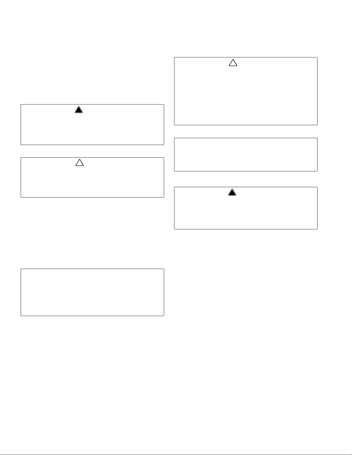
How to Read a Model Number
Accessories
BAFFLE FOR MANITOWOC® ICE MACHINES
When installing a Manitowoc Ice Machine on a
dispenser, a baffle kit is required for proper installation.
The baffle kit is designed to prevent ice from lying
against the front of the ice machine, and melting down
the front of the dispenser. There are two different baffle
kits available for “S” series ice machines, one kit is for
the 30" wide machine, and the other kit is for the 22"
wide machine. There is also a kit for “Q” series ice
machines.
Kits are available through your local distributor. List
prices may be subject to change without notification.
Please call your local parts distributor for current pricing
before ordering.
NOTE: For full information about ice machine
installation, including plumbing lines connections and
electrical requirements, see the ice machine installation
manual.
Part Number 020003996 4/12 1-1
Page 8
General Information Section 1
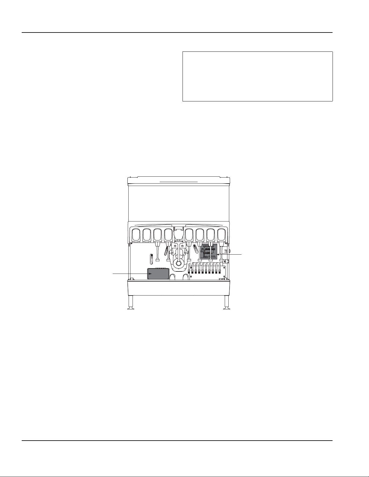
Label
MANUAL FILL LID FOR DISPENSERS WITH AN ICE MACHINE
If you are top mounting your dispenser with an ice
machine, you will require a lid for the manual fill area at
the top, front of the dispenser.
If you ordered a dispenser and an ice machine at the
same time, the manual fill lid was included with the unit.
The manual fill lid can be ordered from your local
distributor.
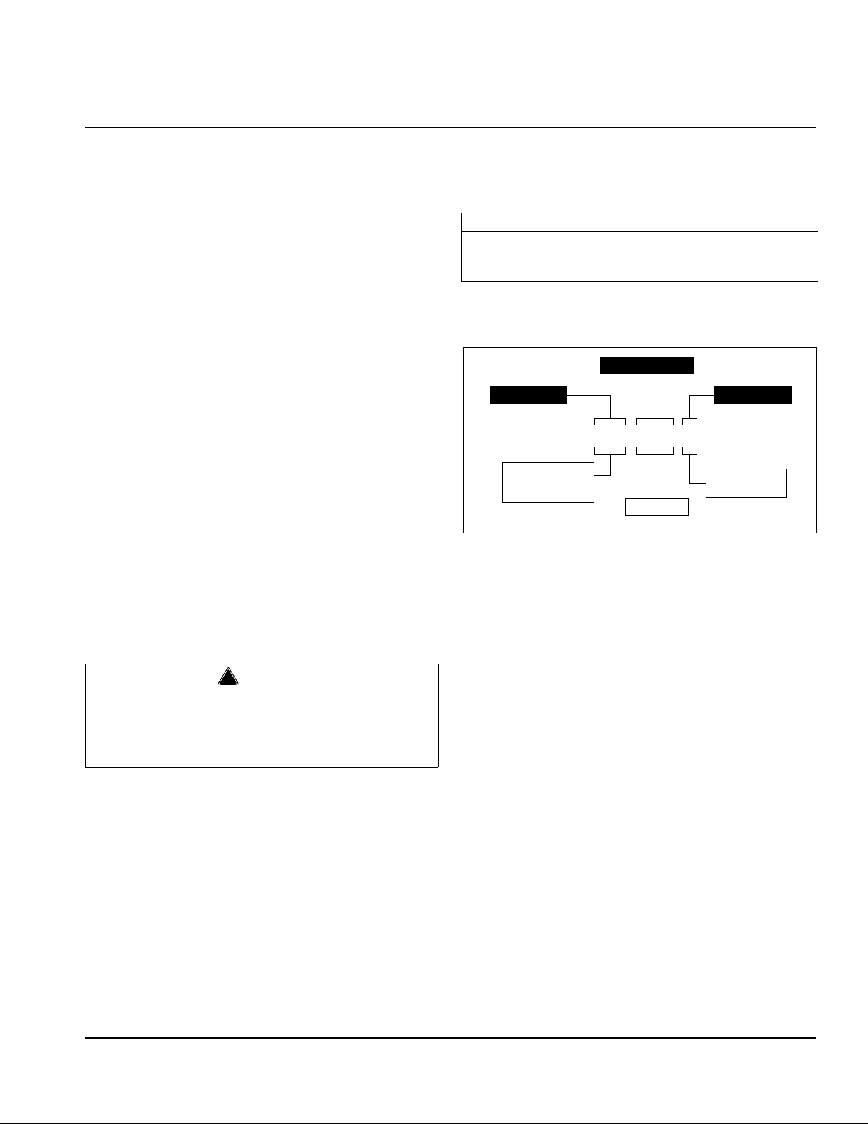
ICE FLOW RESTRICTOR
An optional ice flow restrictor decreases the amount of
ice allowed to enter the ice chute by blocking a small
area at the entrance of the dispenser chute . Th is in tur n
restricts the flow of ice that is dispensed into your cup.
Please refer to the instructions included in kit #5013822
for more information on how to install.
Ice Flow Restrictor
LEGS
Legs are optional equipment with most MBE dispen sers.
Sta ndard legs a re 4" ( 10.2 cm) t a ll st ainless stee l legs. If
an ice machine is installed on top of the dispenser, legs
must not be installed. We do not recommen d using legs
when an ice machine is mounted on the dispenser. The
combined weight of the dispenser , ice and ice machine
is more evenly distributed when the base area of the
dispenser is in contact with the counter top.
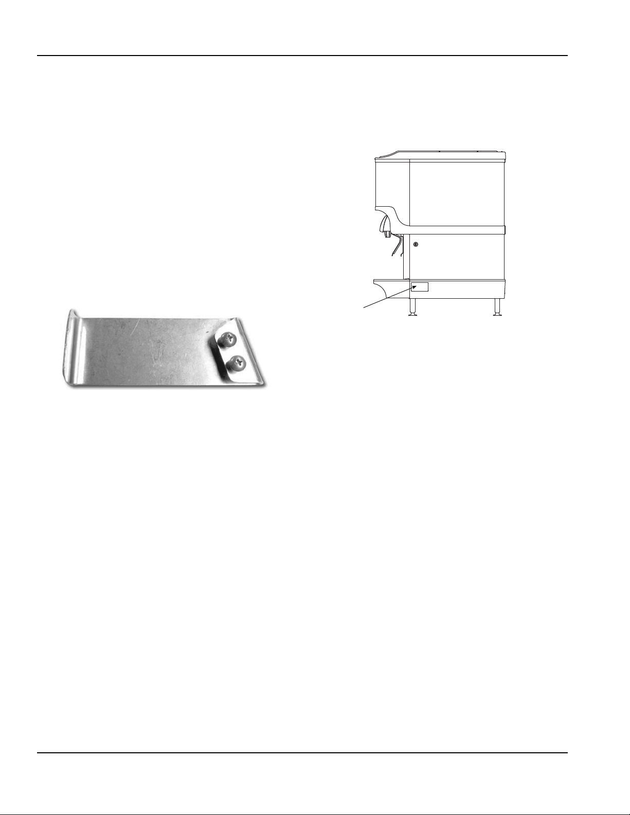
Serial Number Location
This number is required when requesting information
from your local distributor. The serial number is listed on
the SERIAL NUMBER DECAL affixed to the dispenser.
Serial Number Location
Warranty Information
Consult your local MBE Distributor for terms and
conditions of your warranty. Your warranty specifically
excludes all beverage valve brixing, general
adjustments, cleaning, accessories and related
servicing.
Your warranty card must be returned to MBE to activate
the warranty on this equipment. If a warranty card is not
returned, the warranty period can begin when the
equipment leaves the MBE factory.
No equipment may be returned to MBE without a written
Return Materials Authorization (RMA). Equipment
returned without an RMA will be refused at MBE’s dock
and returned to the sender at the sender’s expense.
Please contact your local MBE distributor for return
procedures.
1-2
Part Number 020003996 4/12
Page 9
General
Important
Section 2
Installation Instructions
These instructions are provided to assist the qualified
installer. Contact your Manitowoc Beverage Equipment
Service Agent or call Manitowoc Beverage Equipment
for information regarding start-up service s.
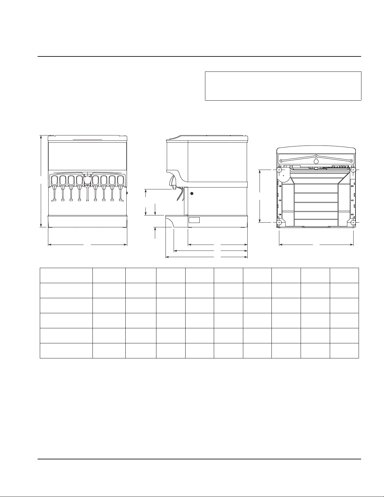
Dimensions
A
C
D
B
Failure to follow these installation guidelines may
affect warranty coverage.
H
E
F
G
I
Model/Ice
Capacity
S/SV-150 34.81"
S/SV-175 34.81"
S/SV-200 34.81"
S/SV/NGF-250 39.81"
S/SV/NGF-250QD 39.88"
ABCDEFGHI
(88.4 cm)
(88.4 cm)
(88.4 cm)
(101.1 cm)
(101.3 cm)
23.00"
(58.4 cm)
25.00"
(63.5 cm)
30.00"
(76.2 cm)
30.00"
(76.2 cm)
30.00"
(76.2 cm)
9.94"
(17.6 cm)
9.94"
(17.6 cm)
9.94"
(17.6 cm)
9.94"
(17.6 cm)
9.94"
(17.6 cm)
4.44"
(11.3 cm)
4.44"
(11.3 cm)
4.44"
(11.3 cm)
4.44"
(11.3 cm)
4.44"
(11.3 cm)
22.63"
(57.5 cm)
22.63"
(57.5 cm)
22.63"
(57.5 cm)
22.63"
(57.5 cm)
22.63"
(57.5 cm)
28.00"
(71.1 cm)
28.00"
(71.1 cm)
28.00"
(71.1 cm)
28.00"
(71.1 cm)
28.00"
(71.1 cm)
31.13"
(79.1 cm)
31.13"
(79.1 cm)
31.13"
(79.1 cm)
31.13"
(79.1 cm)
31.13"
(79.1 cm)
20.00"
(50.8 cm)
20.00"
(50.8 cm)
20.00"
(50.8 cm)
20.00"
(50.8 cm)
20.00"
(50.8 cm)
20.44"
(51.9 cm)
22.44"
(57.0 cm)
27.44"
(69.7 cm)
27.44"
(69.7 cm)
27.44"
(69.7 cm)
Part Number 020003996 4/12 2-1
Page 10
Installation Instructions Section 2
C
A
D
B
Minimum Area
for Cutout
Maximum Area
for Cutout
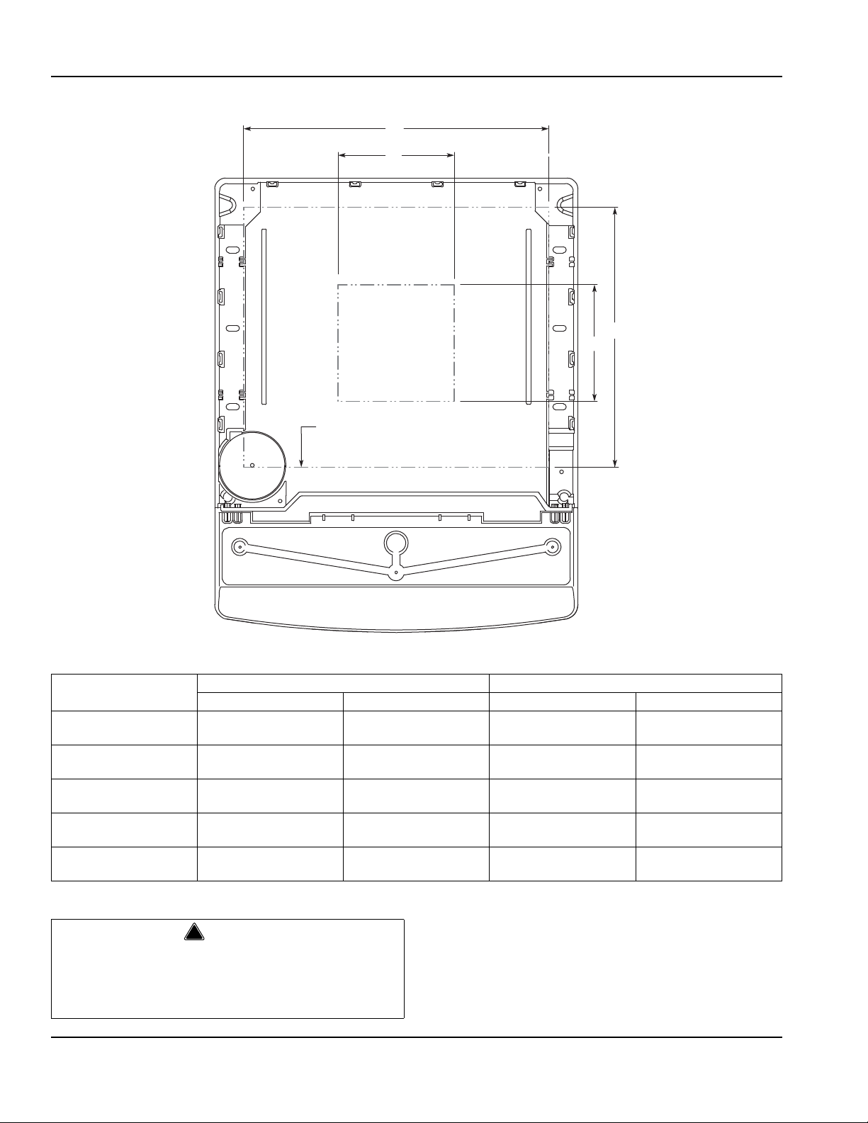
NOTE: Footprint for S/SV-175 shown.
!
Warning
Footprints
S & SV
150 19.00"
175 21.00"
200 26.00"
250* 26.00"
250QD* 26.00"
* Includes NGF
ABCD
(48.3 cm)
(53.3 cm)
(66.0 cm)
(66.0 cm)
(66.0 cm)
Maximum Minimum
Cutting the countertop may decrease its strength.
Counter must be braced to support the dispenser
countertop weight plus ice storage capacity and
weight of ice machine, if applicable.
17.81"
(45.2 cm)
17.81"
(45.2 cm)
17.81"
(45.2 cm)
17.81"
(45.2 cm)
17.81"
(45.2 cm)
8.00"
(20.3 cm)
8.00"
(20.3 cm)
8.00"
(20.3 cm)
8.00"
(20.3 cm)
8.00"
(20.3 cm)
8.00"
(20.3 cm)
8.00"
(20.3 cm)
8.00"
(20.3 cm)
8.00"
(20.3 cm)
8.00"
(20.3 cm)
2-2
Part Number 020003996 4/12
Page 11
Section 2 Installation Instructions
!
Warning
Location
The location selected for the beverage dispenser must
meet the following criteria. If any of these criteria are not
met, select another location.
• The air temperature must be at least 50°F (10°C), but
must not exceed 95°F (35°C).
• The location must not be near heat-generating
equipment or in direct sunlight and must be protected
from weather.
• The countertop must be level. Verify that the
countertop can support the weight of the dispe ns er,
or the dispenser/ice machine combination plus the
weight of the stored ice.
• Water lines, drains and power outlet must be within 6'
(1.8 m) of location.
Carbon Dioxide (CO2) displaces oxygen. Exposure
to a high concentration of CO
which are followed rapidly by loss of con sciousness
and suffocation. If a CO
particularly in a small area, immediately ventilate the
area before repairing the leak. CO
must not be installed in an enclosed space. An
enclosed space can be a cooler or small room or
closet. This may include convenience stores with
glass door self serve coolers. If you suspect CO
may build up in an area, venting of the B-I-B pumps
and / or CO
monitors must be utilized.
2
gas causes tremors,
2
gas leak is suspected,
2
lines and pumps
2
2
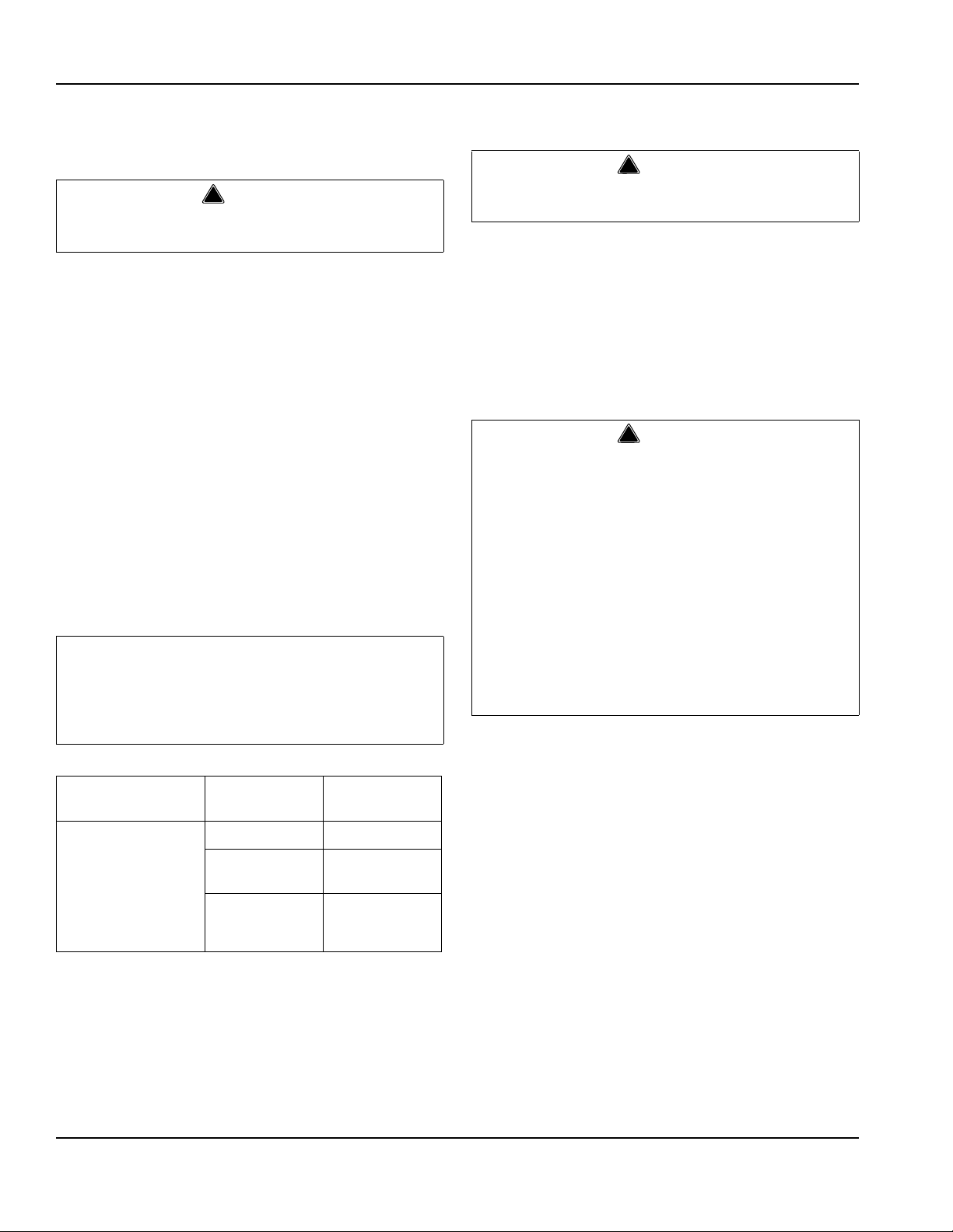
Location Requirements for T op Mounted Ice Machine Installations
Location — Avoid placing the dispenser and/or ice
machine near heat sources such as radiators, ovens,
refrigeration equipment and direct sunlight.
Clearances — Refer to the ice machine installation
manual for clearances.
Front of ice machine to be flush with front of
dispenser — Some ice machines may overhang at the
back of the dispenser.
Drains — A separate drain line is required for the ice
machine, in addition to a drain line for the ice/beverage
dispenser.
Dispensers may require an adapter kit to install some
top-mounted ice machines. Contact your local distributor
for the correct adapter kit.
For full information about ice machine installation,
including clearances, plumbing lines, connections,
and electrical requirements, see the ice machine
installation manual.
Part Number 020003996 4/12 2-3
Page 12
Installation Instructions Section 2
Pre-installation Checklist
When installing any system, first make sure the major components are available. Generally the major components
necessary for an installation are:
Pre-mix System:
CO
regulator set
2
Post Mix System:
CO2 regulator set
Product connectors for Figal tank
Gas connectors for Figal tank
Beverage dispenser
Beverage tubing
tank
CO
2
Figal beverage tanks
Stepless (Oetiker) clamps
Chain for CO
tank
2
Beverage dispenser
Beverage tubing
tank
CO
2
Carbonator
Stepless (Oetiker) clamps
Chain for CO
tank
2
Bulk Syrup System also:
Syrup connectors for Bulk tank
B-I-B System also:
B-I-B connectors
B-I-B regulator set
B-I-B rack
B-I-B syrup boxes
2-4
Gas connectors for Bulk tank
Bulk syrup tanks
Part Number 020003996 4/12
Page 13
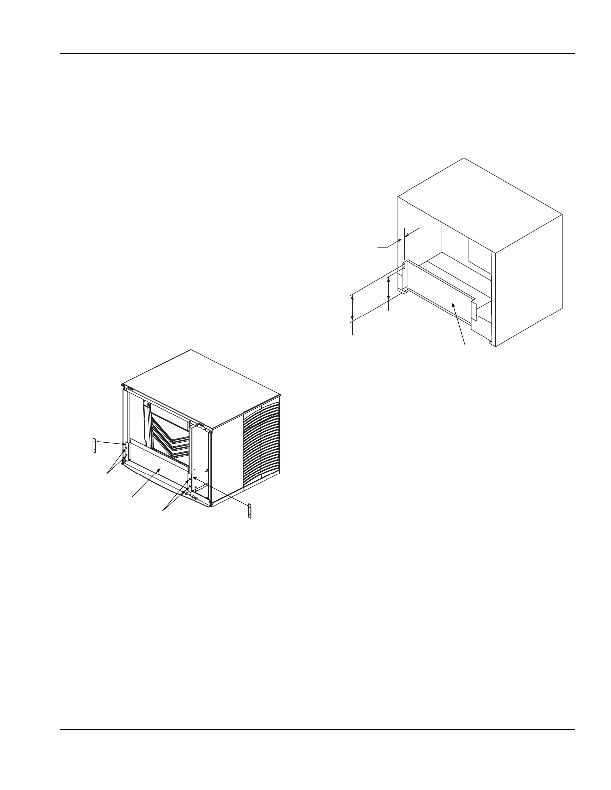
Section 2 Installation Instructions
Backing Plate
to Be Inserted
Into Side
Pocket of
Bulkhead
Screws
Screws
New Ice Baffle
Backing Plate
to Be Inserted
Into Side
Pocket of
Bulkhead
Baffle
0.69"
(1.7 cm)
Ref.
6.32"
(16.0 cm)
Ref.
7.22"
(18.3 cm)
Ref.
Assembly
INSTALLING BAFFLE FOR ICE MACHINE INSTALLATIONS
S Series Baffle
1. Remove both front panels.
2. Examine the ice machine to see if the machine has
four screws on the lower front plastic panels.
3. If there are screws, remove the m from the
countersunk holes on the front surface of the
machine, save the screws.
4. Install the deflector, using the four screws removed
in step three.
5. Four screws and two backing plates are in the kit.
6. If there are no screws on the ice machine (step 2),
pierce the thin plastic countersunk holes, install the
backing plates and install the deflector using the
screws from the kit.
7. Replace the front panels.
Q Series Baffle
1. Position baffle on top of water well with tab on the
front and the other tab inside the water well.
2. Mount the baffle on the left side of the ice machine
using the hole and screw provided.
Q Series Ice Machine
S Series Ice Machine
Part Number 020003996 4/12 2-5
Page 14
Installation Instructions Section 2
!
Warning
Important
!
Warning
!
Warning
Electrical
GENERAL
All wiring must conform to local, state and national
codes.
MINIMUM CIRCUIT AMPACITY
The minimum circuit ampacity is used to help select the
wire size of the electrical supply. (Minimum circuit
ampacity is not the beverage/ice machine’s running amp
load.) The wire size (or gauge) is also dependent upon
location, materials used, length of run, etc., so it must be
determined by a qualified electrician.
ELECTRICAL REQUIREMENTS
Refer to Ice Machine Model/Serial Plate for
voltage/amperage specifications.
VOLTAGE
The standard voltage for S/SV/SVI/NGF Series
dispensers is 120VAC-60Hz. A power cord is provided
with 120VAC-60Hz models only. S/SV/SVI/NGF Series
dispensers use a 1/7 hp gearmotor.
MINIMUM CIRCUIT AMPERAGE CHART
Due to continuous improvements, this information is
for reference only. Please refer to the dispenser
serial number tag to verify electrical data. Serial tag
information overrides information listed on this page.
GROUNDING INSTRUCTIONS
The beverage/ice machine must be grounded in
accordance with national and local electrical codes.
This appliance must be grounded. In the event of
malfunction or breakdown, grounding provides a path of
least resistance for electric current to reduce the risk of
electric shock. This appliance is equipped with a cord
having an equipment-grounding conductor and a
grounding plug. The plug must be plugged into an
appropriate outlet that is properly inst alled and grounded
in accordance with all local codes and ordinances.
Improper connection of the equipment-grounding
conductor can result in a risk of electric shock. The
conductor with insulation having an outer surface
that is green with or without yellow stripes is the
equipment grounding conductor. If repair or
replacement of the cord or plug is necessary, do not
connect the equipment-grounding conductor to a
live terminal. Check with a qualified electrician or
serviceman if the grounding instructions are not
completely understood, or if in doubt as to whether
the appliance is properly grounded. Do not modify
the plug provided with the appliance — if it will not fit
the outlet, have a proper outlet installed by a
qualified electrician.
Dispenser Voltage/Cycle
S-150, S-200, S-250,
SV-150, SV-175,
SV-200, SV-250,
SV-150i, SV-175i,
SV-200i, SV-250i,
SV-250QD, NGF-250,
NGF-250QD
2-6
Circuit Amps
115/60 2.8
220/50, 220/60,
240/50, 240/60
220-240/50 5
(with carb deck)
Minimum
1.5
Part Number 020003996 4/12
Page 15

Section 2 Installation Instructions
!
Warning
PUMP DECK WIRING
The supply cord is equipped with a three prong 5-15P.
When using electric appliances, basic precautions
must always be followed, including the following:
a. Read all the instructions before using the
appliance.
b. To reduce the risk of injury, close supervision is
necessary when an appliance is used near
children.
c. Do not contact moving parts.
d. Only use attachments recommended or sold by
the manufacturer.
e. Do not use outdoors.
f. For a cord-connected appliance, the following
shall be included:
• Do not unplug by pulling on cord. To unplug,
grasp the plug, not the cord.
• Unplug from outlet when not in use and
before servicing or cleaning.
• Do not operate any appliance with a
damaged cord or plug, or after the appliance
malfunctions or is dropped or damaged in any
manner. Contact the nearest authorized
service facility for examination, repair, or
electrical or mechanical adjustment.
g. For a permanently connected appliance — Turn
the power switch to the off position when the
appliance is not in use and before servicing or
cleaning.
When a Ground Fault Circuit Interrupter (GFCI) is
required by code, a breaker type protector must be
used. We do not recommend GFIC outlets as they are
known for more intermittent nuisance trips than panel
breakers. To ensure both the safety and proper
operation of this equipment, be certain that th e electrical
receptacle is a proper design so as to accept this plug,
ensuring that the carbonator assembly is prop e rly
grounded.
If the pump deck is to be installed in an area or
community whose local codes require permanent wiring,
the following procedure must be followed.
1. The three wires (white, black and green) must be fed
through the cable connector and brought into the
wiring compartment. The cable must be secured into
the connector.
2. The green wire from the cable must be connected to
the green screw that attaches to the inside panel of
the wiring compartment. Be sure to use a ring to rque
terminal for connecting the wire to the screw.
3. The white wire from the cable must be joined to the
N terminal of the liquid level control board by a
suitable U.L. listed insulated cable connector.
4. The black wire from the cable must be joined to the
L1 terminal of the liquid level control board by a
suitable U.L. listed insulated cable connector.
h. For an appliance with a replaceable lamp —
Always unplug before replacing the lamp.
Replace the bulb with the same type.
i. For a grounded appliance — Connect to a
properly grounded outlet only. See Grounding
Instructions.
Part Number 020003996 4/12 2-7
Page 16
Installation Instructions Section 2
Important
Plumbing Diagram
Flex Manifold
(for carbonated
units)
Water Supply
RECOMMENDED PLUMBING
The plumbing diagram is printed on a white vinyl label,
located above the inlet tubes for syrup and water. The
plumbing diagram label can be accessed by removing
the splash panel of the dispenser . The plumbing diagram
label explains which inlet coldplate fittings supply which
dispenser valves and water manifolds.
The water supply must first be connected to the
carbonator pump (not shown) before plumbing to
connection “A” shown on plumbing diagram. The
carbonator pump deck must be within six feet of the
dispenser for optimum performance. See BIB inst allation
diagram for system pressure settings.
DIAGRAM & FLEX MANIFOLD LOCATIONS
When installing cold carbonated (Intelli carb)
equipment, never put a tee for the plain water
connection in the line from the pump deck to the
cold plate. Putting a tee in the line will create service
problems and bad drink quality.
NOTE: Valves are read from right to left.
A check valve must be installed in the water supply
line 3 feet from the noncarbonated water connect ion
“PW”. Contact factory if not installed.
2-8
Part Number 020003996 4/12
Page 17

Section 2 Installation Instructions
INTERNAL CARBONATOR TANK
PLUMBING: 2-1-1-2 MANIFOLDING
*OPTIONAL*
VARIETY VALVE ON #3
1 – WATER
(THRU COLDPLATE)
2 – SYRUP
(AMBIENT)
3 – SYRUP
(AMBIENT)
4 – SYRUP
(THRU COLDPLATE)
VALVES “SYRUP LINES NOT SHOWN”
PRE-CHILL OUT TO CARBONATOR
65 4321
23
4
2112
1,2 3 4 5,6
VALVES
CIRCUITS
CO
2
Manifold: Change to carbonated or non-carbonated water.
1. Rotate plunger 180° using a 5/32" Hex Key wrench.
2. Pull plunger up to get non-carbonated water.
3. Push plunger down to get carbonated water.
4. Turn plunger back 180° to lock.
5. Port 5 is not used.
Plain Water
(Plain Water Supply)
CARBONATOR OUT TO POST-CHILL
Plain Water
(From Pump
to Carbonator)
1
#1 #2 #3 #4 #5 #6
Syrup Lines
COLD PLATE
*EXTERNALLY CARBONATED UNITS: CARBONATOR IS REPLACED BY BY-PASS TUBE
FOR ASSISTANCE CALL (812) 246-7000
1
S/SV150 6 Valve Diagram
Part Number 020003996 4/12 2-9
Page 18

Installation Instructions Section 2
1
INTERNAL CARBONATOR TANK
(OPTIONAL)
PLUMBING: 3-1-1-1-2 MANIFOLDING
*OPTIONAL*
VARIETY VALVE ON #4
1 – WATER
(THRU COLDPLATE)
2 – SYRUP
(AMBIENT)
3 – SYRUP
(AMBIENT)
4 – SYRUP
(THRU COLDPLATE)
VALVES “SYRUP LINES NOT SHOWN”
PRE-CHILL OUT TO CARBONATOR
8765
4
3
23
4
211
7, 8 6 5 4
VALVES
CIRCUITS
CO
2
Manifold: Change to carbonated or non-carbonated water.
1. Rotate plunger 180° using a 5/32" Hex Key wrench.
2. Pull plunger up to get non-carbonated water.
3. Push plunger down to get carbonated water.
4. Turn plunger back 180° to lock.
Plain Water
(Plain Water Supply)
CARBONATOR OUT TO POST-CHILL
Plain Water
(From Pump
to Carbonator)
1
#1 #2 #3 #4 #5 #6
Syrup Lines
COLD PLATE
*EXTERNALLY CARBONATED UNITS: CARBONATOR IS REPLACED BY BY-PASS TUBE
FOR ASSISTANCE CALL (812) 246-7000
2
1
3
1, 2, 3
#7 #8
1
S/SV175 8 Valve Diagram
2-10
Part Number 020003996 4/12
Page 19

Section 2 Installation Instructions
1
PLUMBING: 3-1-1-1-2 MANIFOLDING
*OPTIONAL*
VARIETY VALVE ON #4
1 – WATER
(THRU COLDPLATE)
2 – SYRUP
(AMBIENT)
3 – SYRUP
(AMBIENT)
4 – SYRUP
(THRU COLDPLATE)
NOTE: SYRUP LINES NOT SHOWN
PRE-CHILL OUT
TO CARBONATOR
8
7
6543
23
4
311
1, 2, 3 4 5 6
VALVES
CIRCUITS
CO
2
Manifold: Change to carbonated or non-carbonated water.
1. Rotate plunger 180° using a 5/32" Hex Key wrench.
2. Pull plunger up to get non-carbonated water.
3. Push plunger down to get carbonated water.
4. Turn plunger back 180° to lock.
Plain Water
(Plain Water Supply)
CARBONATOR OUT
TO POST-CHILL
Plain Water
(From Pump
to Carbonator)
1
#1 #2 #3 #4 #5 #6
Syrup Lines
COLD PLATE
*EXTERNALLY CARBONATED UNITS: CARBONATOR IS REPLACED BY BY-PASS TUBE
FOR ASSISTANCE CALL (812) 246-7000
21
2
7, 8
#7 #8
VALVES
INTERNAL
CARBONATOR
TANK
(OPTIONAL)
S/SV200/250/SV-250QD 8 V alve Diagram
Part Number 020003996 4/12 2-11
Page 20

Installation Instructions Section 2
INTERNAL
CARBONATOR
TANK
(OPTIONAL)
PLUMBING: 3-1-2-1-3 MANIFOLDING
PRE-CHILL OUT
TO CARBONATOR
876543
321
1, 2, 3 4 5, 6 7
VALVES
CIRCUITS
CO
2
Manifold: Change to carbonated or non-carbonated water.
1. Rotate plunger 180° using a 5/32" Hex Key wrench.
2. Pull plunger up to get non-carbonated water.
3. Push plunger down to get carbonated water.
4. Turn plunger back 180° to lock.
Plain Water
(Plain Water Supply)
CARBONATOR OUT
TO POST-CHILL
Plain Water
(From Pump
to Carbonator)
1
Syrup Lines
COLD PLATE
FOR ASSISTANCE CALL (812) 246-7000
21
3
8, 9, 10
NOTE: SYRUP LINES NOT SHOWN
10 9
VALVES
#1 #2 #5 #6 #7 #8 #9 #10#3 #4
S/SV200/250 10 Valve Diagram
2-12
Part Number 020003996 4/12
Page 21

Section 2 Installation Instructions
NGF-250 & NGF-250QD 8 Valve Diagram
VALVES
VALVES
W/2 VARIETY VLVS STANDARD NO VARIETY VLV
VALVES
SYRUP #4
SYRUP #12
SYRUP #11
SYRUP #10
SYRUP #6
SYRUP #8
SYRUP #5
SYRUP #9
SYRUP #7
W/2 VARIETY VLVS
SYRUP #12
SYRUP #11
SYRUP #10
SYRUP #8
SYRUP #5
SYRUP #9
SYRUP #4
SYRUP #7
SYRUP #6
W/3 VARIETY VLVS
SYRUP #3
SYRUP #2
SYRUP #1
PLAIN WATER
PLAIN WATER
TO CARBONATOR
SYRUP #3
SYRUP #2
SYRUP #1
PLAIN WATER
PLAIN WATER
TO CARBONATOR
VARIETY VALVE
KEY PAD
W-WATER
3-FLAVOR
2-FLAVOR
1-FLAVOR
CO
2
INTERNAL
CARBONATOR
TAN K
(OPTIONAL)
VARIETY VALVE
CARBONATOR OUT TO POST-CHILL
BLOCK
MANIFOLD TO CHANGE TO CARBONATED
OR NON-CARBONATED WATER
1) ROTATE PLUNGER 180O USING A 5/32”
ALLEN WRENCH
2) PULL PLUNGER OUT TO GET NON-CARB WATER.
PUSH PLUNGER IN TO GET CARB WATER
3) TURN PLUNGER BACK 180
PRE-CHILL OUT TO CARBONATOR
O
SYRUP #12
SYRUP #11
SYRUP #10
TO LOCK
SYRUP #9
SYRUP #8
SYRUP #7
SYRUP #6
SYRUP #4
SYRUP #5
SYRUP #3
VALVE S
CIRCUITS
SYRUP #2
SYRUP #1
PLAIN WATER
PLAIN WATER TO CARBONATOR
COLD PLATE
*A & *B ARE AMBIENT SYRUP LINES ADDED FOR THE 3RD VARIETY VALVE..
LINE TO BE PLUGGED WHEN NOT IN USE.
SYRUP #12
SYRUP #11
SYRUP #10
SYRUP #8
SYRUP #5
SYRUP #3
SYRUP #2
SYRUP #1
PLAIN WATER
PLAIN WATER
SYRUP #9
SYRUP #4
SYRUP #7
SYRUP #6
TO CARBONATOR
SYRUP LINE (S#) / CARB ONLY LINE (C) / MANIFOLD LINE (W/C)
*EXTERNALLY CARBONATED UNITS: CARBONATOR TANK IS REPLACED BY BY-PASS TUBE.
020002170
Part Number 020003996 4/12 2-13
Page 22

Installation Instructions Section 2
Pressure
Relief
Drain Pan
SV-200 & 250
Rear of Unit
To Drain
90° Elbow Fitting
Radiator Clamp
Flexible Tubing
Straight Fitting
Radiator Clamp
Flexible Tubing
Rear Access for Drain
Hose and Beverage Lines
Drainage Through Bottom Drainage Through Back Rear View
CO2 Supply
ROUTING INTERNAL CARB TANK PURGE TUBE
Some models are equipped with an internal carbonation
tank. These models require that the purge/pressure
relief tubing be routed to a drain.
1. Remove the splash panel.
2. Uncoil tubing and route between the front of the
dispenser and the drain pan.
4. Verify the tubing is not kinked and then secure
tubing to maintain a minimum 1" (2.5 cm) air gap at
the drain. Follow any applicable local or national
codes.
3. Depending on drain location route the tubing
through the tubing bundle cutout or out the back of
the dispenser.
Drains
S/SV/SVI/NGF Series dispensers drain through a double connection to the drain pan.
2-14
Part Number 020003996 4/12
Page 23

Section 2 Installation Instructions
Collector
Box
Straight Fittings 90° Fittings
Drain Line
Fittings
Drain Line
Fitting
Drain Line
Collector
Box
Step by Step Installation
GENERAL
S/SV/SVI/NGF Series dispensers have a stainless steel
cabinet and lighted merchandiser standard.
Beverage valves, coldplate connections, drain
connections and electrical components are front
serviceable.
SPECIFICATIONS CHART
Min. Max
Water pressure 40 psi 55 psi
Ambient temperature 40°F
(4°C)
CO2 pressure 40 psi 50 psi
Electrical 1 15V/60 Hz/1 230V/50-60 Hz/1
Pre-mix pressure
Normal 60 psi*
Diet 40 psi*
B-I-B 60 psi or according to line run
Carbonation
105°F
(41°C)
UNIT INSTALLATION
1. Place the dispenser in the desired location.
2. Run the beverage lines and water lines; make sure
to install the water connections to the proper inlets.
Connection “A” comes from the brass carbonator
pump and connection “B” is your plain water supply.
Install Plumbing Drains & Insulate
3. Connect Drain Kit to drain pan (See Drains Section 2-14).
4. Extended splash panel units do the following:
A. Remove the extended splash panel from the unit
by removing the two (2) phillips head screws
holding it in place.
B. Determine drain setup and screw either the 90°
or straight line drain fittings into the collector box
included with the drain kit
(See Drains Section 2-14).
Cold 75 psi
Ambient 90 psi 105 psi
quickdraw CO2 supply 75 psig
quickdraw regulator
40 psig 50 psig
valve
quickdraw Carbonation
Cold 75 psi
Ambient 90 psi 100 psi
* This is the optimal pressure. When the foam is too high, decrease
the pressure; when spitting/popping is an issue, increase the
pressure.
NOTE: Depending on the drain setup connect the straight
fittings to the collector box if the drain lines are to run straight
back underneath the unit or the 90° fittings if the drain lines
run down through the counter top.
C. Using the provided radiator clamps connect and
secure the drain lines to the collector box fitting s
with a standard screwdriver or 5/16 nut driver.
Part Number 020003996 4/12 2-15
Page 24

Installation Instructions Section 2
Important
Left Bracket
Tab
Right
Bracket Tab
Left Slot
Right Slot
Left Tab In
Slot
Right Tab In
Slot
90° Elbow
90° Elbow
!
Warning
Important
Important
D. Mount the collector box to the bracket by sliding
the right and left bracket tabs into the slots on
the collector box.
E. Be sure the 90° rubber ice bin drain elbows are
routed into the collector box.
F. Reinstall the extended splash panel.
5. Fill bin with ice.
6. Set flexible manifold Carb/Non-Carb drinks for correct drink
settings (See Recommended Plumbing Section 2-8).
7. Turn water supply on to the dispenser.
8. Purge air from the carbonator tank. Lift the pressure
relief valve tab on the carbonator tank until water comes
out of the relief valve.
9. Connect the pump deck control lead to the pump motor .
10. Connect power supply cords. (There are (2) two cords
that need to be connected to a 115V power supply.)
1 1. Brix beverage valves (See Brix Check Section 3-10)
and fill bin with ice.
When installing cold carbonated (Intelli carb) equipment,
never put a tee for the plain water connection in the line
from the pump deck to the cold plate. Putting a tee in the
line will create service problems and bad drink quality.
QUICKDRAW INSTALLATIONS
Personal Injury - Hazardous Moving Parts
Do not adjust regulator valve above 50 psig.
Recommended operating parameters are 40-50 p sig.
NOTE: The quickdraw unit requires a supply of CO
pressure requirement for the CO
adjustable Ice Dispense CO
supply is 75 psig. The
2
regulator in the electric box
2
must be set at 40 to 45 psi. The Ice Dispense CO
. The
2
Regulator
2
must never be set above 50 psi.
Turn CO
supply on to the dispenser. Each cold carb pump
2
deck is furnished with a fixed regulator set at 75 psi. Ambient
units need to be set between 90 and 100 psi.
The ice portion sizes must be adjusted to customer
requirements at the time of installation. (See the quickdraw
Ice Portion Adjustments section for more information.)
SETTING PRESSURES
Pre-mix Pressures
Normal pre-mix pressure regulators must be set at 60 PSI.
Diet pre-mix pressure regulators must be set at 40 PSI. If you
are experiencing high foaming, decreasing the pressures may
correct the problem. Spitting and popping usually requires
slightly increasing the pressures. Pre-mix beverage valve
pressures vary by type and manufacturer. Please consult the
manufacturer of the valves you are using for specific
instructions regarding operation of the valve.
Cold Carb and Ambient System Pressures
1. Incoming tap water - must be at a minimum dynamic
pressure of 40 psi and maximum static pressure of 55 psi
(measured at inlet to pump).
2. BIB pressure gauge must be set for 60 psi or according to
your line run.
3. Carbonator Pressure gauge (Use Preset Regulator):
- Cold Carbonation set for 75 psi.
- Ambient systems must be set at 90 psi to 105 psi.
2-16
If incoming water pressure is under 40 psi, a water booster
is recommended. If incoming water pressure is over 55 psi,
a water regulating valve is required.
Part Number 020003996 4/12
Page 25

Section 2 Installation Instructions
Drain Pan
ADA Ribbon Cable
ADA Harness
ADA Box
Ribbon Cable
ADA Box
Ribbon Connector
ADA Box
Ribbon Cable
ADA Harness
ADA Wire
Harness Clip
Important
Connected ADA
Cables
Drain Pan
ADA Box
ADA KEY PADS
These instructions are for installations with this option.
1. Remove power from the unit.
Merchandiser Removal
2. Loosen the two knurled fasteners located in the top of
the merchandiser that hold the merchandiser in place.
3. Remove the merchandiser by lifting up and tilting
forward.
Splash Panel Removal
4. Remove the splash panel from the unit by removing the
two (2) phillips head screws holding it in place.
ADA Wiring
5. Route the ADA ribbon cable under the drain pan.
moving parts or panels wh en they are placed back on
the unit.
Drain Pan & ADA T ouch Pad Box
9. Attach the drain pan to the unit.
10. Center the ADA Key Pad Box with the unit in front of the
drain pan and secure into pl ace.
6. Continue routing the ADA cable behind the valve mount
cap on the left hand side of the unit.
7. Connect the ADA ribbon cable to the ADA wire harness
located to the left of the ice chute and held to the foam
front by a wire clip.
If mounting the ADA Box directly in front of the drain p an
on the counter top leave a minimum of 1 inch space
between the bottom edge of the drain pan and the ADA
Box to allow space for drain pan removal.
1 1. Apply corresponding drink labels to the ADA key pads.
NOTE: Drinks correspond from left to right on the left side of the
unit, and right to left on the right side of the unit. If buttons are not
used they will be blanked out. The Cubed/Crushed buttons are
only utilized on units configured with the Selectable Ice feature.
(See ADA Key Pad Matrix Section 2-18)
8. Neatly tuck in and take up any slack remaining in the
ADA ribbon cable so it will not be in the way of any
Part Number 020003996 4/12 2-17
Page 26

Installation Instructions Section 2
12345 678910
123 4 56
Cubed Crushed
Cubed Crushed6 Valve Dispensers
12345678910
1234 5678
Cubed Crushed
Cubed Crushed8 Valve Dispensers
12345 678910
12
10 Valve Dispensers
345 6 78910
Cubed Crushed
Cubed Crushed
Important
ADA Key Pad Matrix
STARTING YOUR BEVERAGE SYSTEM & DISPENSER
Upon completion of the beverage dispenser and / or
system installation, all tubing, dispenser, and system
components must be cleaned and sanitized prior to use.
NOTE: At installation, equipment, dispensers, and tubing
get moved through many environments, dirt, dust, chases,
insulation, drywall, etc. It is an important procedure and
best practice to address cleaning to deliver the best quality
drink to your customer.
Clean and sanitize the water and syrup circuits
according to instructions provided in this manual.
Clean and sanitize the dispenser components
according to instructions provided in this manual.
Seal to counter top when no legs are used with the
unit. Consult and use local health codes if a
discrepancy occurs between this manual and your
local health codes.
Finish Installation
12. Put the splash panel and merchandiser back onto the
unit and reinstall the screws that hold them in place.
13. Restore power to the unit.
2-18
Part Number 020003996 4/12
Page 27

General System Overview
1800
75
60
Dispenser
Carbonator Tank
Carbonate,
Non-carbonate
Beverage Manifold
Counter top
Syrup
Tap Water
Tap Water
CO
2
CO
2
CO2 Cylinder
Bag-in-box
Syrup
Carton
CO
2
BIB Syrup
Pump
90-
1800
60
105
Dispenser
Counter top
Syrup
Tap Water
Tap Water
CO
2
Carbonated
Water
CO
2
Cylinder
CO
2
w/Cold plate
BIB Syrup
Pump
Syrup
Syrup
Non-carbonated
Water
Carbonator Tank
Bag-in-box
Syrup
Carton
Syrup
CO
2
Section 3
Operation
Typical Internal Carbonation Beverage Dispensing System
Part Number 020003996 4/12 3-1
Typical External Carbonation (Ambient) Beverage Dispensing System
Page 28

Operation Section 3
Merchandiser
Soda Valves
Key Switch
Carb/Non-Carb Water manifold
and Syrup/Soda Inlet
(Behind Splash Panel)
Drainpan Grid
Drainpan
Splash Panel
Counter
Component Identification
3-2
Part Number 020003996 4/12
Page 29

Section 3 Operation
RECOMMENDED ICE OTHER ICE SIZES AND SHAPES
Dice
7/8" x 7/8" x 7/8"
(2.2 x 2.2 x 2.2 cm)
Half Dice
3/8" x 1-1/8" x 7/8"
(1.0 x 2.9 x 2.2 cm)
Contour
3/8" x 1-1/4" x 1-1/4"
(1.0 x 3.2 x 3.2 cm)
Mini
7/8" Dia. x 3/4" Long
(2.2 cm Dia. x 1.9 cm Long)
Gourmet-Small
1" Dia. x 3/4"
(2.5 cm Dia. x 1.9 cm)
Crescent Cube
0.75"
(1.9 cm)
0.38"
(1.0 cm)
1.13"
(2.9 cm)
Sequence of Operation
ICE RECOMMENDED FOR DISPENSING
Dispensers are designed to dispense hard, cube ice up
to one-inch square. The ice shapes and sizes listed
above are recommended for dispensing. Warm “Super
Cooled” Ice Before Dispensing: “Super Cooled” ice is not
recommended for dispensing. “Super cooled” ice is ice
that has been stored in freezers below 32°F. must it be
necessary to temporarily use “super cooled” ice, allow
the ice to warm at room temperature for 25 to 30
minutes before placing the ice in the dispenser.
ICE STORAGE AND DISPENSING
As the customer presses the rocking chute, the arm at
the top left rear of the chute pushes upward on the door
lock. The door opens until it contacts the stops in the
mounting brackets. The plastic arm on the ice ch ute also
activates the lever of the ice dispensing switch. When
activated, the micro switch starts the gear motor. The
gear motor turns the paddle wheel and agitator arm.
The paddlewheel carries ice. Periodic agitation is
standard on the 30" and larger dispensers. During
periodic agitation, the paddle wheel and agitator turn for
approximately three seconds every three and one halfhours. The door lock prevents ice from being dispensed
during the agitation cycle.
BEVERAGE VALVES
Post-mix beverage valves are designed to precisely
meter the flow of both water and syrup to obtain the
proper mixing ratio. The syrup and soda w ate r
components of the post-mix beverage a re mixed as th ey
leave the beverage valve.
ROCKING CHUTE ICE DISPENSING
As the customer presses the rocking chute, the arm at
the top left rear of the chute pushes upward on the door
lock. The door opens until it contacts the stops in the
mounting brackets. The plastic arm on the ice chute also
activates the lever of the ice dispensing switch. When
activated, the micro switch starts the gear motor. The
gear motor turns the paddle wheel and agitator bar.
CARBONATION
The purpose of the carbonator is to take regular tap
water at street water pressure (minimum 20 PSI,
maximum 80 PSI, dynamic or flowing pressure) 1/2"
water line and increase the water to beverage system
pressure (usually 100 PSI). This water is then combined
with the CO
same pressure, the CO
gas. Because the water and gas are at the
2
will dissolve into the water.
2
Chilling the mixture before dispensing will assist in
locking the carbon dioxide into the water. After
dispensing, the CO
The CO
will gradually leave the liquid due to pressure
2
may be unlocked from the liquid.
2
and temperature changes.
Components
The components of the carbonator are: water pump, an
electric motor to operate the pump, carbonator tank
where the water and CO
mix, and a water level control.
2
Part Number 020003996 4/12 3-3
Page 30

Operation Section 3
From Water Supply
To Noncarbonated
Water Inlet Barb
Water to
Carbonator
Pump
Filter
Water Regulator
40–55 PSI
Booster System
(If Required)
To CO
2
Manifold (BIB
Pumps) from
CO
2
Supply
60 PSI
T o Syrup Inlet
Barbs on Unit
T o BIB Pumps
from BIB
To BIB
Pump
BIB
Operation
Carbon Dioxide (CO
arrives at the carbonator tank through the gas inlet.
Water supply enters the carbon ator pump inlet at regular
street water line pressure (minimum 20 PSI, maximum
80 PSI, dynamic or flowing pressure). The water pump
increases the pressure of the water, which allows the
water to flow into the carbonator tank. The CO
water mix together in the carbonator to produce the
carbonated water that is then sent to the soda dispenser.
The agitation of the water and CO
under high pressure creates the soda water. The quality
of carbonation (percent of CO
increases as the water temperature decreases and
exposure time increases.
The water level in the carbonator tank is controlled by a
water level control in the tank. This control turns the
pump motor off and on to maintain a preset level of liquid
in the tank. The water level control may be electronic
probes or a mechanical float.
SYRUP DELIVERY SYSTEM
Y our syrup location can va ry depending on the volume of
beverages served and ease of accessibility. Your
beverage system may set in a back storage room or
under the counter of the dispenser. Configurations are
almost limitless. Check the temperatures expected for
the storage location. Adverse temperatures can affect
the storage and quality of beverage products. It is
recommended the temperature of storage location must
not fall below 40°F (4°C) or rise above 90°F (32°C).
2
) leaves the storage tank and
and the
2
together in the tank
2
mixed in the water)
2
BACK ROOM PACKAGE
1. Incoming tap water – must be at a minimum
dynamic pressure of 40 psi and maximum static
pressure of 55 psi.
2. Carbonator Water pump motor – Powers the
water pump. The water pump motor is part of the
carbonator pump deck.
3. Carbonator Water pump – Pumps tap wa ter into
the carbonator tank. The water pump is part of the
carbonator. The incoming water for the carbonator
must be first run through the pump before
connecting to the proper cold plate inlet.
4. Internal/External Carbonator tank – Combines
CO
gas and tap water to form carbonated water.
2
The “carbonator” is the carbonator tank, water pump
and water pump motor.
5. CO
cylinder – Holds highly pressurized carbon
2
dioxide (CO
aluminum cylinder tank. CO
). The CO2 cylinder is a steel or
2
gas flows through the
2
primary pressure regulator.
6. BIB pressure gauge – Set for a minimum of 60 psi.
Indicates CO
pressure going to B-I-B pumps.
2
3-4
Part Number 020003996 4/12
Page 31

Section 3 Operation
7. Primary pressure regulator – Lowers the CO2 gas
pressure, to 100 psi, so the CO
gas will be at the
2
proper pressure to enter the carbonator regulator.
8. Lowered outgoing pressure – Set for 75 psi.
Gauge indicates lowered outgoing pressure from the
CO
cylinder after being routed through the primary
2
pressure regulator at 100 psi.
9. Secondary pressure regulator – Lowers the CO
gas pressure before the CO
pump. CO
pressure activates the syrup pump.
2
gas flows to the syrup
2
2
10. Syrup pump – Draws syrup out of the bag-in-box
syrup package. Syrup flows through the syrup lines
to the dispenser for chilling, then dispensing. There
is a syrup pump for each bag-in-box syrup system.
11. Bag-In-Box syrup cartons – Box which contains a
plastic bag, filled with syrup.
RACKING
Regardless if you are working on a B-I-B or Figal
system, a place will be designated for placement of the
product. A rack (or shelf) system affords systematic
placement and complete usage of the beverage p aid for.
The B-I-B rack allows the boxes to lay properly for syrup
dispersal. Please check with your B-I-B syrup supplier.
Some boxes must be slightly tilted down, while others
may be in virtually any position. The Figal tank rack
keeps the newer and full tanks organized at one end of
the beverage line with the partial tanks at the othe r.
B-I-B
The Bag-In-Box system refers to a plastic disposable
bag. The B-I-B normally contains 5 gallons of syrup,
however some locations offer 2-1/2 gallon B-I-B units.
This plastic bag is then held inside a cardboard or other
container. B-I-B systems are for post-mix applications
only.
PUMPS
The syrup in a B-I-B system is delivered to the beverage
system through gas operated pumps. These pumps
extract the syrup out of the bags, forcing th e sy r up
throughout the system.
AUTO BAG SELECTORS
These are used on higher volume B-I-B systems where
two or more bags of the same product are connected to
one pump and one system. An auto bag selector is
essentially a valve that automatically changes from one
bag (or series of bags) to another bag (or series of bags)
of syrup as the bags empty, allowing a constant flow of
product.
Part Number 020003996 4/12 3-5
Page 32

Operation Section 3
Carbonated Water to Dispenser
3/8 Syrup Lines to Dispenser
Incoming
Water
Carbonator
100 psi
CO
2
Soda Water
Pump
Important
1
RED
NO
2
3
6
4
5
COM NC
FIGAL SYSTEM
Figal refers to the stainless steel tanks of pre-mix
beverage or post-mix syrup. A small CO
tank pushes
2
the beverage out of the figal tank.
AGITATION TIMER
The timer is non-adjustable and is set to agitate the ice
for 3 seconds every 3.5 hours. Activating the dispenser
will reset the timer. After 3.5 hours of non-use, the timer
will energize the dispenser motor.
The LED tells the technician in which mode the timer is
operating. Rather than a jumper pin, this timer has a
female spade connector that must be connected to
terminal number 6.
When this jumper is in place, the LED will blink at
one-second intervals, this is the run mode.
When the jumper is open, the LED will flash every
0.4 second. This is the test mode and the timer will cycle
every 55 seconds in test mode. If the timer is left in test
mode, it will automatically reset to run mode.
FIGAL TANKS
The stainless steel Figal beverage tanks are easy to
store and connect. When using the Figal tanks:
• Use a gas connector for the inlet fitting of the tank.
• Use a syrup connector for the outlet fitting of the
tank.
• If more than one Figal tank is connected in series,
when changing tanks, remove the tank closest to the
original gas inlet while adding the new tank to the
connector closest to the syrup outlet.
Most Figal tanks have a self-closing valve on the tank as
well as the gas and syrup connectors. This allows the
operator of the system to change tanks without having to
shut down the entire system. With this type of connector ,
push down on the connector while pulling up on the snap
ring around the opening of the connecto r. Then simply
pull the connector off the tank.
Agitation Timer
quickdraw ice & beverage dispensers do not have
an agitation timer and need to be left in Auto Mode
at night so periodic ice agitation takes place.
3-6
Part Number 020003996 4/12
Page 33

Section 3 Operation
Door Stops
Door Lock
Door
Ice Delivery
Switch
Door Stops
Door
Door Lock
1/16"
to
1/4"
Tab
Switch Arm
Operation Checks and Adjustments
ROCKING CHUTE ICE DELIVERY SWITCH ADJUSTMENT
To properly adjust the switch, first unplug the power cord
to the unit then remove the merchandiser. This will give
you access to the ice delivery switch located on the left
side of the rocking chute.
The left side of the rocking chute has a tab that pushes
up on the ice delivery switch. To adjust it, use needle
nose pliers and bend the arm of the switch up or down in
order to change the point where the tab makes contact
with the switch arm.
Begin by observing the chute by slowly pushing against
the rocking chute. When the ice delivery switch clicks,
measure the distance from the doo r stops on the rocking
chute bracket to the door. The distance between the two
must be no more than 1/4" (0.64 cm), but no less than
1/16" (0.16 cm).
Part Number 020003996 4/12 3-7
Page 34

Operation Section 3
SMALLEST SIZE /
DECREASE BUTTON
MANUAL PUSH
FOR ICE SWITCH
DISPLAY HIDDEN
PROGRAM
SWITCH
ICE DISPENSE
POWER SWITCH
ICE DISPENSE
MODE SWITCH
LARGEST SIZE /
INCREASE BUTTON
MANUAL
AUTO
QUICKDRAW ICE PORTION ADJUSTMENTS
The quickdraw ice dispensing system has adjustable ice portion sizes. Follow the directions below to set the ice
portion size. Each portion size must be checked according to customer specification at the time of installation.
1. To set the ice portion sizes, press the program
switch 1 time in 3 seconds. The display will read
“0001”.
2. Press the ice portion size that is to be adjusted.
Once the portion size that is to be adjusted is
pressed, the display will show the present pulse
setting for that size.
3. To increase the portion size, press the largest size
button. To decrease the portion size, press the
smallest size button.
NOTE: The pulse count will increase, or decrease, by 1
with each press of the smallest or largest size buttons.
4. Press the program button 1 time to exit program
mode and save settings.
5. Repeat steps 1 through 4 for each cup size as
necessary.
NOTE: For Data Display Mode, and Test Mode
instructions please refer to the quickdraw Portio n
Control Program flow chart in this manual.
3-8
Part Number 020003996 4/12
Page 35

Section 3 Operation
Emitter
Receiver
Beam
Left Adjustment Screw
Rectangular Window in Ice Chamber
SENSOR BEAM
Sensor Beam Sequence of Operation
1. Ice fills the ice chute until it interrupts the beam.
2. Paddlewheel stops.
3. Ready for the next portioned dispense.
Adjustment
1. Loosen screws on left & right side of assembly.
3. Tighten screws on left & right side of assembly.
4. Test the Quick Draw.
2. Adjust Sensor board sensor eyes to the center of the
rectangular window on ice chamber.
Part Number 020003996 4/12 3-9
Page 36

Operation Section 3
6:1
5.5:1
8.5:1
5:1
WATER
5.5
to 1
8.5
to 1
9
10
8
7
6
5
4
3
2
OZ.
SYRUP
WATER
SYRUP
RATIOS
High Yield Brix Cup
BRIX CHECK
Step 1 - Gather Tools
Tools you will need; brix cup and S tube.
NOTE: Follow instructions on 2a or 2b depending on
Valve Type that is being checked.
Step 2a - Attaching S Tube To Multi-flavor Valve
• Remove nozzle and syrup diffuser from valve.
• Slide white end of S Tube over tip of diffuser snuggly.
• Re-attach nozzle and diffuser with S Tube in place.
• Select flavor to brix.
Step 2b - Attaching S Tube To Single Flavor Valve
Step 4 - Fill Brix Cup
• Position the large end of the brix cup under the valve.
At the same time insert the free end of the S tube into
the proper syrup chamber. See diagram to the right
for reference.
• Dispense product until product reaches the grid on
the Brix cup.
NOTE: The water should be clear. If the water is not
clear, the S-lube has not been attached correctly to the
syrup diffuser. Repeat step 2.
Step 5 - Read The Brix
• Remove nozzle and syrup diffuser from valve.
• Slide white end of S Tube over tip of diffuser snuggly.
• Re-attach nozzle and diffuser with S Tube in place.
Step 3 - Prime S Tube
• Remove filled brix cup from dispenser and tap on
counter 3 times. Place on flat surface.
• Look a the grid lines. The water and syrup levels
should be +/- 2 bars of each other.
• Repeat steps 1-5 for each different product that will
be brixed.
NOTE: If Brix ratio is not correct, contact service
After nozzle has been re-attached, dispense a small
company.
amount of product to fill up the S Tube.
• This is necessary to ensure an accurate reading.
3-10
Part Number 020003996 4/12
Page 37

Section 4
!
Caution
!
Warning
!
Warning
Maintenance
Cleaning
DAILY CLEANING
All cleaning must meet your local health department
regulations. The following cleaning instructions are
provided as a guide.
Use only warm soapy water to clean the exterior of
the tower. Do not use solvents or other cleaning
agents. Do not pour hot coffee into the drain pan.
Pouring hot coffee down the drain pan can
eventually crack the drain pan, especially if the
drain pan is cold or still contains ice.
Clean the dispensing valves:
6. Remove nozzles and diffusers from beverage
valves.
Electric Shock Hazard
Unplug unit before servicing or cleaning.
When using cleaning fluids or chemicals, rubber
gloves and eye protection must be wor n.
Clean the exterior and drain pan:
1. Turn off the key switch located on either right or left
side of the unit.
2. Lift the grid and remove it from the drain pan.
3. Using mild soap, warm water and a clean cloth, wipe
the drain pan and splash panel. Then, rinse with
clean, warm water. Allow plenty of warm (not hot)
water to run down the drain of the drain pan, to
remove syrup residue that can clog the drain
opening.
4. Wash the grid, then rinse with clean water. Place the
grid back in the drain pan.
5. Wash all exterior surfaces of the unit with warm
water and a clean cloth. Wipe again with a clean, dry
cloth.
Nozzle Removal
7. Rinse nozzle and diffuser with warm, clean water.
8. Clean nozzles and diffusers with soapy water and a
soft bristle brush.
9. Clean the underside of the beverage valves with
warm, soapy water. Rinse with clean damp towel.
10. Replace nozzles and diffusers on valves.
11. Turn on the key switch.
Part Number 020003996 4/12 4-1
Page 38

Maintenance Section 4
!
Warning
!
Warning
MONTHLY CLEANING
6. Prepare 2 gallons of sanitizing solution by mixing
1/2 ounce of household bleach (that contains 5.25 %
Unplug unit before servicing or cleaning ice bin.
Ice bin contains part s tha t can move at any time and
will cause injury if hands are in the way.
When using cleaning fluids or chemicals, rubber
gloves and eye protection must be worn .
Clean and sanitize the ice bin:
1. Unplug unit and remove all ice from the ice bin.
2. Mix a solution of mild detergent to clean the
dispenser bin and components.
3. Wash the ice bin using a sponge and the mild
detergent solution.
4. Using the mild detergent solution and a soft bristle
brush or clean cloth, clean the following dispenser
parts:
• Entire bin
• Paddle wheel
• Paddle wheel area
•Agitator
• Paddle wheel pin
• Ice Chute
• Rear bushing
• Motor shaft
• Strip lids (where applicable)
5. Rinse all the parts in clean, running water.
sodium hypochlorite) with 2 gallons of 120°F water.
The mixture must not exceed 100 PPM of chlorine.
Or mix a solution of any approved sanitizer,
following the directions for mixing and applying the
sanitizer.
7. Sanitize the ice bin and cold plate with the sanitizing
solution for at least 10 seconds.
8. Allow to air dry. Do not rinse.
Re-assembling the dispenser parts:
9. Re-assemble parts in the following order:
• Bin liner
• Paddle wheel
•Agitator
• Paddle wheel pin
• Ice chute
• Merchandiser
10. Hand tighten all knurled fastene rs.
11. Pour in fresh, sanitary ice and replace the plastic lid
on the top of the dispenser.
12. Plug in the unit’s electrical cord.
13. Check for proper ice dispensing.
CLEANING CHECKLIST
•Check CO
the primary regulator gauge will point to a shaded
area that reads “Low CO
Cylinder.”
• Check syrup supply.
• Clean drain pan, grid, and splash panel.
• Clean the valve nozzles and diffusers.
supply . If CO2 supply is low, an arrow on
2
” or “Change CO2
2
4-2
Part Number 020003996 4/12
Page 39

Section 4 Maintenance
A
G
F
E
C
D
B
Preventive Maintenance
Preventative maintenance is a vital part of keeping your
dispenser in top condition. Following the guidelines
below will assist you in continued trouble-free operation
of your unit.
1. Conduct daily maintenance of the machine.
2. Perform monthly maintenance of the machine.
3. Perform periodic maintenance and sanitizing of
beverage system.
4. Do not overfill the dispenser bin with ice.
5. Do not allow the dispenser to sit for prolonged
periods of non use with ice in the bin.
6. Most ice dispenser service problems are caused by
low usage of the ice dispenser.
7. Do not allow ice to remain in the bin more than a day
in order to prevent ice from freezing together and/or
stagnant ice.
Possible excess ice storage reasons:
• Storage capacity exceeds daily requirements.
• Low demand during the off season.
• Dispenser oversized with future growth in mind.
Lower ice storage to meet one day’s needs. If you
manually fill ice, fill only with the appropriate amount of
ice. Fill the dispenser with fresh ice each morning. Do
not fill the dispenser at night just before shut down. Ice
cubes can freeze together if not dispensed.
Disassembly
DISASSEMBLY FOR CLEANING AND MAINTENANCE
NOTE: Sanitize the ice dispenser at Initial Start-up in
addition to monthly sanitizing. You will need a slotted
screwdriver in order to disassemb le.
Disassemble parts in the following order:
A. Merchandiser
B. Ice chute
C. Paddle wheel or agitator pins
D. Agitator
E. Paddle wheel
F. Bin liner
G. Paddle wheel area
Beverage/Ice Dispenser
Accessing a Dispenser Bin Top Mounted with a
Manitowoc Ice Machine:
1. Remove the front panel of the ice machine.
2. Remove the ice deflection baffle. This will give you
access to the dispenser bin.
3. If the Manitowoc ice machine is operating, wait for
the sheet of ice to fall into the dispenser bin.
When the ice sheet falls into the dispenser bin,
immediately place toggle switch of the ice machine to
the OFF position. If the Manitowoc ice machine is NOT
operating, place the toggle switch of the ice machine to
the OFF position.
4. On models without a top mounted ice machine,
remove the plastic lid from the top of the dispenser.
5. Remove all ice from the dispenser .
6. Disconnect electrical powe r to the dispenser.
Part Number 020003996 4/12 4-3
Page 40

Maintenance Section 4
2
1
7. Remove agitator arm and paddlewheel pin.
Non-front Serviceable Motor
a. Rotate the agitator arm so the paddle wheel pin
handle is pointing up, toward the ceiling.
b. Prepare agitator pin for removal by removin g the
stainless steel split ring.
c. Then remove the paddle wheel pin from the hole
in the agitator.
d. Push the agitator bar toward the back of the unit
until the agitator is free of the paddle wheel hub.
Front Serviceable Motor
a. With agitator arm in any position remove hitch
clip pin from the mushroom bushing on the rear
of the ice bin.
b. Push the agitator bar toward the bushing to
remove it from the paddle wheel hub.
NOTE: If a top mount ice machine is installed, sliding the
ice machine to one side will make bin component
removal easier. If the ice machine is hard plumbed it will
need to be disconnected.
8. Remove paddle wheel, bin liner and paddle wheel
area.
9. Move the front of the agitator to one side and slide
the agitator forward until the rear of the agitator shaft
is clear of the bushing.
10. Remove the agitator from the bin area.
11. Slide the paddle wheel from its shaft.
12. Loosen the four knurled fasteners that hold the bin
liner in place.
13. Remove the bin liner.
14. Remove the paddle wheel area from the bin.
15. Discard the remaining ice in the bin.
DISASSEMBLE THE ROCKING CHUTE
NOTE: For all quickdraw units, refer to the quickdraw
Components section for ice chute information.
1. Loosen the two knurled fasteners that hold the
merchandiser in place.
2. Remove the merchandiser.
3. Remove outer bracket.
4. Remove door lock.
5. Remove door.
6. Remove ice chute.
4-4
Non-front Serviceable
4
5
6
Front Serviceable
Ice Chute Removal
Part Number 020003996 4/12
Page 41

Section 4 Maintenance
Beverage Valve
Switch
Ice Dispense Switch
QUICKDRAW COMPONENTS
1. Turn the beverage valve switch on the front left side
to the off position.
2. Place a receptacle (bucket or large cup) under the
ice dispense chute.
3. Place the ice dispense switch to MANUAL mod e.
The door will open and ice will fall into the bucket
or cup.
4. Remove the ice chute cover:
B. Push the bottom of chute to rear until it stops.
C. Rock top of the chute forward until top of chute
clears unit.
A. Grab the tabs on the back of chute and spread,
pulling tabs off of pins.
5. Mix a solution of mild detergent to clean the
quickdraw components. Using the deterg ent solution
and a soft bristle brush or clean cloth, clean the
following components:
• Cup locator
• quickdraw chamber
• Door
• Ice chute cover
6. Rinse all parts in clean running water.
7. Mix a sanitizing solution of 1/4 ounce liquid,
unscented bleach (5.25% CL NaO concentration) for
each gallon of water. The mixture must provide 100PPM available chlorine.
8. Using the sanitizing solution, a soft bristle brush, or
a clean cloth, sanitize the components listed in Step
Part Number 020003996 4/12 4-5
Page 42

Maintenance Section 4
Removable Front
Merchandiser Panel
Agitator
Ice Bin
Ice
Paddle Wheel
Rocking Chute
Ice Dispense Chute
Drain Pan
Gear Motor
Water Line
Beverage Valve
(Option)
5. The ice chamber must be sanitized with a soft
bristle brush to adequately clean the drainage area.
9. Reverse the procedure to reassemble the quickdraw
mechanism.
10. Place the ice dispense switch to the AUTO position,
and place the beverage valve switch to the ON
position.
11. Check for proper operation.
NON-FRONT SERVICEABLE GEAR MOTOR REMOVAL
These instructions are provided as a guide for the
removal of the gear motor. Depending on the model
number of your dispenser, these instructions may vary
slightly.
1. Disconnect power from the electric receptacle.
2. Remove all ice from the ice storage bin of the
dispenser.
3. Remove the paddle wheel pin from the paddle
wheel/agitator assembly inside the dispenser bin.
4. Remove the agitator assembly from the dispenser
bin by pushing the agitator to the back of the bin.
Angle the front of the agitator to the side. Pull the
agitator forward then out of the dispenser.
5. Remove the paddle wheel from the dispenser by
pulling the hub of the paddle wheel to the back of the
bin and off the gear motor shaft.
6. Remove the splash panel from the dispenser and
expose the gear motor.
7. Disconnect the electric connector from the gear
motor wire leads.
8. Remove the pin in front of the gear motor.
9. Y ou m ust be able to remove the gea r motor from the
dispenser.
10. To install a replacement gear motor, reverse this
procedure.
4-6
Part Number 020003996 4/12
Page 43

Section 4 Maintenance
FRONT SERVICEABLE GEAR MOTOR REMOVAL
These instructions are provided as a guide for the removal of the gear motor . Depend ing on the model number of your
dispenser, these instructions may vary slightly.
1. Unplug the dispenser.
2. Unplug the motor.
3. Remove motor mount pins.
4. Slide motor towards you.
5. Notice alignment of the chamfered edge of drive
shaft.
6. New motor must have the same alignment (within
15 degrees).
7. To get correct alignment you can do one of two
things:
a. Turn drive shaft with an adjustable wrench,
being careful not to damage the drive shaft.
b. Plug in the unit, plug in the motor and use the
ice dispense switch to move the drive shaft into
correct alignment.
8. If you plugged in the unit to help with alignmen t of
drive shaft now unplug the unit.
9. Slide motor up into housing, making sure that the
tabs fit on the bracket.
10. Install motor mount pins.
11. Plug in motor.
12. Test unit.
Part Number 020003996 4/12 4-7
Page 44

Maintenance Section 4
!
Warning
!
Warning
Bag
side
connector
Sanitizing
BEVERAGE SYSTEM CLEANING
Flush sanitizing solution from syrup system.
Residual sanitizing solution left in system could
create a health hazard.
When using cleaning fluids or chemicals, rubber
gloves and eye protection must be worn .
Sanitize the beverage system at initial start-up as well as
regularly scheduled cleaning. The drain pan must be in
place under soda valves, to carry away detergent and
sanitizing agents that will be flushed through valves.
BAG-IN-BOX SYSTEM SANITATION
The procedure below is for the sanitation of one
syrup circuit at a time. Repeat to sanitize additional
circuits.
You will need the following items to clean and sanitize
the Bag-in-Box (BIB) beverage system:
• Three (3) clean buckets
2. Disconnect the “syrup-line side” of the bag-in-box
connector.
3. Rinse connector with warm tap water.
4. Connect syrup connector to BIB connector and
immerse both into Bucket 1. A “bag-side” connector
can be created by cutting the connector from an
empty disposable syrup bag.
• Plastic brush or soft cloth
• Mild detergent
• Unscented bleach (5% Na CL O) or
Commercial sanitizer
• Bag-In-Box bag connector
1. Prepare the following in the buckets:
• Bucket 1 — warm to hot tap water for rinsing.
• Bucket 2 — mild detergent and warm to hot
water.
• Bucket 3 — mix a solution of unscented bleach
(5% Na CL O) or commercial sanitizer and warm
to hot water. Mixture must supply 100 PPM
available chlorine (1/4 oz. bleach to 1 gallon
water).
4-8
Part Number 020003996 4/12
Page 45

Section 4 Maintenance
!
Caution
5. Draw rinse water through system until clean water is
dispensed. Most beverage valves allow the syrup
side to be manually activated by depressing the
syrup pallet.
6. Connect Bucket 2 to system.
7. Draw detergent solution through system until
solution is dispensed.
8. Repeat steps 2-7 until all syrup circuits contain
detergent solution.
9. Allow detergent solution to remain in the system for
5 minutes.
10. Connect Bucket 3 to system.
11. Draw sanitizing solution through system until
solution is dispensed.
12. Repeat step 11 until all syrup circuits contain
sanitizer solution.
13. Allow sanitizer solution to remain in system for 15
minutes.
14. Remove nozzles and diffusers from beverage
valves.
15. Scrub nozzles, diffusers and all removable valve
parts (except electrical parts) with a plastic brush or
a soft cloth and the detergent solution.
16. Soak nozzles, diffusers and removable valve parts
(except electrical parts) in sanitizer for 15 minutes.
17. Replace nozzles, diffusers and valve part s.
18. Connect Bucket 1 to system.
19. Draw rinse water through system until no presence
of sanitizer is detected.
20. Attach syrup connectors to BIBs.
21. Draw syrup through system until only syrup is
dispensed.
22. Discard first 2 drinks.
2. Disconnect all product and water lines from product
tanks and remove carbonator.
3. Locate the Figal syrup tank for the circuit to be
sanitized. Remove both quick disconnects from the
Figal syrup tank. Rinse quick disconnects in tap
water.
4. Connect rinse tank to the syrup line. Draw clean
rinse water through the valve until syrup is flushed
from the system.
5. Connect detergent tank to the syrup line and draw
detergent through the valve for two minutes. Then,
allow remaining detergent to stay in the system for
five minutes.
6. Connect rinse tank to the syrup line. Draw clean
rinse water through the valve until detergent is
flushed from the system.
7. Remove valve nozzle and diffuser as shown in Daily
Cleaning instructions. Using a plastic brush or a soft
cloth and warm water , scrub the nozzle, diffuser,
bottom of the dispensing valve and cup lever, if
applicable.
8. Place removable valve parts (EXCEPT solenoids) in
sanitizing solution for 15 minutes.
9. Replace valve diffuser and nozzle on the beverage
valve.
10. Connect sanitizer tank to the syrup line and draw
sanitizer through the valve for two minutes. Allow
sanitizer to remain in the system for a minimum of
15 minutes.
11. Reconnect syrup and carbonated water lines.
12. Draw syrup through the lines to rins e the sys te m.
Discard drinks until at least two cups of satisfactory
tasting beverage are dispensed through the valve.
Shipping, Storage and Relocation
FIGAL BEVERAGE SYSTEM
1. Prepare the following in three clean Figal tanks:
• Rinse tank - fill with room temperature tap water.
• Detergent tank - mix approved beverage system
cleaner with warm water as directed.
• Sanitizing tank - mix a solution of unscented
bleach (5% Na CL O) or commercial sanitizer
and warm to hot water. Mixture must supply 100
PPM available chlorine (1/4 oz. bleach to
1 gallon water).
Part Number 020003996 4/12 4-9
Before shipping, storing, or relocating this unit,
syrup systems must be sanitized. After sanitizing, all
liquids (sanitizing solution and water) must be
purged from the unit. A freezing environment
causes residual sanitizing solution or water
remaining inside the unit to freeze, resulting in
damage to internal components.
Page 46

Maintenance Section 4
THIS PA GE INTENTIO NALLY LEFT BLANK
4-10
Part Number 020003996 4/12
Page 47

Section 5
Before Calling for Service
Checklist
If a problem arises during operation of your dispenser, follow the checklist below before calling service. Routine
adjustments and maintenance procedures are not covered by the warranty.
Problem Possible Cause To Correct
Dispenser will not dispense ice (and NO
SOUNDS are heard when machine is
activated).
Dispenser will not dispense ice (motor
runs but no ice movement is heard in
bin).
Excessive clustering or bridging of ice. Loaded ice not broken up. (Caution:
Ice dispenses continuously. Misaligned microswitch. Adjust microswitch.
Thumping noise or irregular sound at a
particular area of the dispenser.
Dispensing crushed ice or reduced
dispensing speed.
Door will not close. Ice jammed in chute . Adjust bridge in ice machine or, when
Mounting brackets for rocking chute have
spread too far apart.
No power. Check electrical connection.
Loose wire in electrical system. Thoroughly check all wire connections.
Dispenser overloaded with ice. Remove ice from dispenser until unit will
operate.
Motor not working. Check thermally protected motor.
Replace motor or capacitor if necessary.
No ice in bin. Fill dispenser with ice.
Door not opening. Check rocking chute mechanism or
electric solenoid operation.
Paddle wheel pin slipped from the paddle
wheel.
Super cooled ice is not covered by the
Servend warranty.)
Excessive water spilling from the ice
machine.
Poorly adjusted ice machine. Adjust ice machine to eliminate large
Extremely low usage of the dispenser. Lower the ice level in the bin.
Agitation timer set incorrectly. Test agitation timer.
Shaved ice clusters in the bin. Remove clusters, discover why ice is
Water spillage from ice machine into
dispenser bin.
Agitation timer. Test agitation timer.
Bridge of ice sheet is too thick. Adjust ice machine.
Paddle wheel area broken or cracked. Replace paddle wheel area.
Ice clusters in bin. Break up or remove clusters.
Door not fully open. Adjust door.
Door and/or door lock has come out of
place.
Replace paddle wheel pin.
Break ice clusters before manually filling
the dispenser. (See ice
recommendations.)
Adjust ice machine to eliminate water
spillage.
waffle shapes.
shaving, and then repair.
Adjust ice machine.
manually filling, break up clusters.
Replace door and lock into proper
position.
Bend parts into shape.
Part Number 020003996 4/12 5-1
Page 48

Before Calling for Service Section 5
Drink T roubleshooting
Condition Investigation Check Correction
Water only dispensing No pressure Regulator(s) out of adjustment Check/adjust regulator(s).
Install fresh tank.
2
line pinched, kinked or
Check/repair/replace CO2 line.
or reset breaker.
Replace water filter.
Check/clean/replace pump strainer.
Check/clean/repair water check valve.
Check for frozen water line. Internal
carbonator unit only.
motor, electrode or liquid level control.
Install fresh tank.
2
line pinched, kinked or
Check/repair/replace CO2 line.
Adjust CO
pressure due to leaks Repair CO2 leaks.
2
Clean out the lines.
if necessary.
replace regulator if necessary.
pressure or change the tank.
2
pressure or replace regulator
2
supply. Reset pressure or
2
Syrup and CO
only
2
Carbonator No power Check power supply. Plug in carbonator
dispensing
Syrup and plain water
No pressure Out of CO
only dispensing
One valve will not
dispense anything
Beverage dispensed is
too sweet
Beverage is not sweet
enough
Is there power to the
valve?
Is the ratio (brix) of the
drink correct?
Is the ratio (brix) of the
drink correct?
Drinks are foaming Are system pressures
correct?
No water, syrup or gas
dispensing
Is there power to the
unit?
Is power coming
through the key
switch?
Is there power to the
key switch?
Out of CO
Defective regulator(s) Check/repair/replace regulator(s).
CO
2
obstructed
Water supply Make sure water is turned “on”.
Defective carbonator Check/repair/replace carbonator pump,
HP regulator out of adjustment Adjust HP regulator to the proper setting.
Defective HP regulator Check/repair/replace HP regulator.
CO
2
obstructed
Broken wire or loose connection Replace/repair wire or connector.
Bad microswitch Replace microswitch.
Flow control out of adjustment Adjust the flow control.
Insufficient soda flow due to low
carbonator pressure
Low CO
Obstruction in the water or soda
line
Flow control out of adjustment Adjust the flow control.
Soda flow too high Reset CO
Obstruction in syrup line Clean out the syrup line.
Over carbonation Check CO
Dirty lines/valves Clean/sanitize entire system.
No power Plug in unit or reset breaker.
Power to control box Replace fuse or control box.
Key switch “off” Turn switch “on”.
Key switch defective Replace key switch.
No power through the transformer Reset/replace transformer.
5-2
Part Number 020003996 4/12
Page 49

Section 5 Before Calling for Service
1. Remove probe electronics.
2. Pass magnetic tip of screwdriver by
lower end of tube extending from
electronics package.
3. Reed switch will close.
4. Carbonator operates.
Pump Troubleshooting
Problem Possible Cause Corrective Action
Pump motor does not
shut off
Problem with probe or probe harness
Pump motor
Problem with probe or probe harness
intermittent
Pump motor does not
pump
Water pressure from water source is not
high enough
quickdraw Mechanism Troubleshooting
Problem Possible Cause Corrective Action
Ice dispense door is
not closing
Ice portion size is
increasing
Ice portion size is
erratic
supply is low.
CO
2
CO
regulator set too low.
2
Toggle switch is in the OFF or MANUAL
position.
Power is disconnected from unit.
supply is low.
CO
2
regulator set too low.
CO
2
Sensor board and main board are not
communicating properly.
Sensor board and main board are not
communicating properly.
Verify water pressure leading into pump inlet is 40 psi
minimum.
Replenish CO
supply.
2
Check regulator setting and adjust to 40 - 45 psig.
Move toggle switch to the AUTO position.
Plug unit in.
Replenish CO
supply.
2
Check regulator setting and adjust to 40 - 45 psig.
Check main board/sensor board communication process.
Check main board/sensor board communication process.
Part Number 020003996 4/12 5-3
Page 50

Before Calling for Service Section 5
SUPPLY POWER ON
SWITCH IN
AUTO MODE
POWER UP
DISPLAYS
“8888” THEN
“____”
DISPENSE
CHUTE FILLED
W/ ICE
AUTO
MODE
PRESS ANY SIZE
BUTTON TO
DISPENSE
PROGRAMMED
SIZE
FIXED MAXIMUM
TIME IS 6 SEC IF
PROGRAMMED
PULSE COUNT IS
NOT REACHED
TURN SWITCH
TO OFF TO
RESET, THEN FIX
OUT OF ICE
CONDITION
DISPLAY SHOWS
“_ICE”
INDICATING OUT
OF ICE
AUGER TIMES
OUT IN 30 SEC
IF CHUTE
CANNOT BE
FILLED W/ICE
SWITCH IN
MANUAL MODE
TO MANUALLY
DISPENSE
PRESS AND HOLD
“MANUAL PUSH
FOR ICE” SWITCH
PRESS ONE (1)
TIME (IN 3S)
PROGRAM
MODE
DISPLAY
“0001”
SET TOTAL
PULSES FOR
EACH SIZE
PRESS TWO (2)
TIME (IN 3S)
DATA DISPLAY
MODE “0002”
READ NO. OF
DISPENSES FOR
EACH SIZE SINCE
LAST RESET
(9999) MAX
PRESS THREE (3)
TIME (IN 3S)
TEST MODE
MODE “0003”
MANUALLY CYCLE
SENSORS &
MOTORS FOR
TROUBLESHOOTING
REMOVE ICE IN
CHUTE &
MANUALLY
BLOCK SENSOR
WITH PAPER
“1113” FOR
BLOCKED
“1003” FOR
UNBLOCKED ICE
CHUTE SENSOR
PRESS FOUR (4)
TIMES (IN 3S)
ICE SENSING
MODE “0004”
ADJUSTS
IR BEAM
STRENGTH IN
ICE CHUTE
PRESS SMALL
SIZE BUTTON TO
TEST ICE CHUTE
SENSOR
DISPLAY “1XX3”
ADJUSTABLE
FROM 3-30
FAC TORY
SETTING IS (7)
“0704”
PRESS LARGE
SIZE BUTTON
AGAIN TO
TOGGLE
BETWEEN
“3113” AGITATOR
ON
“3003” AGITATOR
OFF
PRESS SMALL
SIZE BUTTON
TO REDUCE ICE
LEVEL IN CHUTE
(MORE
SENSITIVE IR
BEAM)
PRESS LARGE
SIZE BUTTON
TO INCREASE
ICE LEVEL
IN CHUTE (LESS
SENSITIVE IR
BEAM)
PRESS XLARGE
SIZE BUTTON
AGAIN TO
TOGGLE
BETWEEN “3113”
AIR SOL ON
“3003” AIR SOL
OFF
PRESS LARGE
SIZE BUTTON TO
TEST AGITATOR
DISPLAY “3003”
PRESS PROGRAM BUTTON ONE (1) TIME TO EXIT PROGRAM MODE & SAVE SETTINGS
PRESS XLARGE
BUTTON TO
TEST AIR
SOLENOID
DISPLAY “4003”
REPEAT
FOR
EACH
SIZE
AS
NECESSARY
PRESS ANY SIZE BUTTON TO
DISPLAY ITS RUNNING COUNT
SINCE LAS RESET
REPEAT FOR
ALL SIZES AS
NECESSARY
TO RESET
COUNT TO
ZERO
PRESS &
HOLD ITS
SIZE BUTTON
FOR
3 SECONDS
PRESS THE
LARGE
BUTTON
TO
INCREASE
PULSE
COUNT BY
1 EACH
PRESS
PRESS ANY
SIZE BUTTON
TO DISPLAY
ITS PRESENT
PULSE
SETTING
PRESS THE
SMALL
BUTTON TO
DECREASE
PULSE COUNT
BY 1 EACH
PRESS
ENTER PROGRAM MODE
EXIT PROGRAM MODE
PRESS PROGRAM SWITCH ONCE (1), TWICE (2), THREE (3), OR FOUR (4), TIMES (IN 3 SEC) TO ENTER THESE PROGRAM MODES
YES
NO
OR
YES
NO
quickdraw Ice Portion Control Program
5-4
Part Number 020003996 4/12
Page 51

Page 52

© 2012 Manitowoc
Continuing product improvements
may necessitate change of
specifications without notice.
Part Number 020003996 4/12
Manitowoc Beverage Systems
Sellersburg, IN 47172, USA
Ph: 812-246-7000 Fax: 812-246-7024
Visit us online at: www.manitowocfsg.com
2100 Future Drive
 Loading...