

Page 1
Flavor Magic Module
Integrated & Aftermarket
Installation, Use & Care Manual
This manual is updated as new information and models are released.
Visit our website for the latest manual. www.manitowocfsg.com
Leader in Ice & Beverage Dispensers
Part Number 020001199 012/09
Page 2
Safety Notices
! Warning
!
Caution
Important
!
Caution
Important
! Warning
As you work on Manitowoc equipment, be sure to pay
close attention to the safety notices in this manual.
Disregarding the notices may lead to serious injury and/
or damage to the equipment.
Throughout this manual, you will see the following types
of safety notices:
Text in a Warning box alerts you to a potential
personal injury situation. Be sure to read the
Warning statement before proceeding, and work
carefully.
Text in a Caution box alerts you to a situation in
which you could damage the equipment. Be sure to
read the Caution statement before proc eeding, and
work carefully.
Procedural Notices
As you work on Manitowoc equipment, be sure to read
the procedural notices in this manual. These notices
supply helpful information which may assist you as you
work.
Throughout this manual, you will see the following types
of procedural notices:
Read These Before Proceeding:
Proper installation, care and maintenance are
essential for maximum performance and troublefree operation of your Manitow oc equipment. Read
and understand this manual. It contains valuable
care and maintenance information. If you encounter
problems not covered by this manual, do not
proceed, contact Manitowoc Foodservice Group.
We will be happy to provide assistance.
Routine adjustments and maintenance procedures
outlined in this manual are not covered by the
warranty.
PERSONAL INJURY POTENTIAL
Do not operate equipment that has been misused,
abused, neglected, damaged, or altered/modified
from that of original manufactured specifications.
NOTE: SAVE THESE INSTRUCTIONS.
Text in an Important box provides you with
information that may help you perform a procedure
more efficiently. Disregarding this information will
not cause damage or injury, but it may slow you
down as you work.
NOTE: Text set off as a Note provides you with simple,
but useful, extra information about th e pr oce dur e yo u
are performing.
We reserve the right to make product improvements at any time.
Specifications and design are subject to change without notice.
Page 3

Section 1
General Information
Read This Manual. . . . . . . . . . . . . . . . . . . . . . . . . . . . . . . . . . . . . . . . . . . . . . . . . 1-1
Unit Inspection . . . . . . . . . . . . . . . . . . . . . . . . . . . . . . . . . . . . . . . . . . . . . . . . . . . 1-1
Model Numbers. . . . . . . . . . . . . . . . . . . . . . . . . . . . . . . . . . . . . . . . . . . . . . . . . . . 1-1
Accessories. . . . . . . . . . . . . . . . . . . . . . . . . . . . . . . . . . . . . . . . . . . . . . . . . . . . . . 1-1
Serial Number Location . . . . . . . . . . . . . . . . . . . . . . . . . . . . . . . . . . . . . . . . . . . . 1-2
Warranty Information . . . . . . . . . . . . . . . . . . . . . . . . . . . . . . . . . . . . . . . . . . . . . . 1-2
Section 2
Installation Instructions
General . . . . . . . . . . . . . . . . . . . . . . . . . . . . . . . . . . . . . . . . . . . . . . . . . . . . . . . . . 2-1
Electrical . . . . . . . . . . . . . . . . . . . . . . . . . . . . . . . . . . . . . . . . . . . . . . . . . . . . . . . . 2-2
Recommended Plumbing. . . . . . . . . . . . . . . . . . . . . . . . . . . . . . . . . . . . . . . . . . . 2-4
Step by Step Aftermarket & Integrated Installations. . . . . . . . . . . . . . . . . . . . . 2-5
Starting Your Beverage System & Dispenser . . . . . . . . . . . . . . . . . . . . . . . . . . 2-10
How To Read A Model Number . . . . . . . . . . . . . . . . . . . . . . . . . . . . . . . . . 1-1
Module Kit Contents . . . . . . . . . . . . . . . . . . . . . . . . . . . . . . . . . . . . . . . . . . 1-1
Back Room Kit Contents . . . . . . . . . . . . . . . . . . . . . . . . . . . . . . . . . . . . . . . 1-1
Connectors . . . . . . . . . . . . . . . . . . . . . . . . . . . . . . . . . . . . . . . . . . . . . . . . . 1-2
Sanitary Levers . . . . . . . . . . . . . . . . . . . . . . . . . . . . . . . . . . . . . . . . . . . . . . 1-2
Flavor Magic Serial Number Locations . . . . . . . . . . . . . . . . . . . . . . . . . . . . 1-2
Dimensions . . . . . . . . . . . . . . . . . . . . . . . . . . . . . . . . . . . . . . . . . . . . . . . . . 2-1
Essential Tools . . . . . . . . . . . . . . . . . . . . . . . . . . . . . . . . . . . . . . . . . . . . . . 2-1
Pre-installation Checklist . . . . . . . . . . . . . . . . . . . . . . . . . . . . . . . . . . . . . . . 2-1
General . . . . . . . . . . . . . . . . . . . . . . . . . . . . . . . . . . . . . . . . . . . . . . . . . . . . 2-2
Minimum Circuit Ampacity . . . . . . . . . . . . . . . . . . . . . . . . . . . . . . . . . . . . . 2-2
Voltage . . . . . . . . . . . . . . . . . . . . . . . . . . . . . . . . . . . . . . . . . . . . . . . . . . . . 2-2
Minimum Circuit Amperage Chart . . . . . . . . . . . . . . . . . . . . . . . . . . . . . . . . 2-2
Grounding Instructions . . . . . . . . . . . . . . . . . . . . . . . . . . . . . . . . . . . . . . . . 2-2
General . . . . . . . . . . . . . . . . . . . . . . . . . . . . . . . . . . . . . . . . . . . . . . . . . . . . 2-4
Capacities . . . . . . . . . . . . . . . . . . . . . . . . . . . . . . . . . . . . . . . . . . . . . . . . . . 2-4
Specifications Chart . . . . . . . . . . . . . . . . . . . . . . . . . . . . . . . . . . . . . . . . . . 2-4
Pre-installation . . . . . . . . . . . . . . . . . . . . . . . . . . . . . . . . . . . . . . . . . . . . . . 2-5
MDH-302/402 Module . . . . . . . . . . . . . . . . . . . . . . . . . . . . . . . . . . . . . . . . . 2-5
SV-150/175/200/250 Module . . . . . . . . . . . . . . . . . . . . . . . . . . . . . . . . . . . 2-6
SYrup & CO2 Lines . . . . . . . . . . . . . . . . . . . . . . . . . . . . . . . . . . . . . . . . . . . 2-7
Finalizing Installation . . . . . . . . . . . . . . . . . . . . . . . . . . . . . . . . . . . . . . . . . . 2-9
Page 4

Section 3
Operation
Section 4
Maintenance
Table of Contents (continued)
General System Overview . . . . . . . . . . . . . . . . . . . . . . . . . . . . . . . . . . . . . . . . . . 3-1
Component Identification . . . . . . . . . . . . . . . . . . . . . . . . . . . . . . . . . . . . . . . 3-1
Racking . . . . . . . . . . . . . . . . . . . . . . . . . . . . . . . . . . . . . . . . . . . . . . . . . . . . 3-1
B-I-B . . . . . . . . . . . . . . . . . . . . . . . . . . . . . . . . . . . . . . . . . . . . . . . . . . . . . . 3-1
Pumps . . . . . . . . . . . . . . . . . . . . . . . . . . . . . . . . . . . . . . . . . . . . . . . . . . . . . 3-1
Programming Modes. . . . . . . . . . . . . . . . . . . . . . . . . . . . . . . . . . . . . . . . . . . . . . . 3-2
Program Dispense Time . . . . . . . . . . . . . . . . . . . . . . . . . . . . . . . . . . . . . . . 3-2
PURGE/SANITIZE . . . . . . . . . . . . . . . . . . . . . . . . . . . . . . . . . . . . . . . . . . . . 3-2
DISPENSING MODES . . . . . . . . . . . . . . . . . . . . . . . . . . . . . . . . . . . . . . . . 3-2
CHANGING NUMBER OF ACTIVE FLAVORS . . . . . . . . . . . . . . . . . . . . . . 3-2
TOUCH PAD LED . . . . . . . . . . . . . . . . . . . . . . . . . . . . . . . . . . . . . . . . . . . . 3-3
TIME DELAY AFTER DISPENSE . . . . . . . . . . . . . . . . . . . . . . . . . . . . . . . . 3-3
Control Logic Matrix . . . . . . . . . . . . . . . . . . . . . . . . . . . . . . . . . . . . . . . . . . . . . . . 3-4
PREVENTATIVE MAINTENANCE . . . . . . . . . . . . . . . . . . . . . . . . . . . . . . . . . . . . . 4-1
Cleaning Checklist . . . . . . . . . . . . . . . . . . . . . . . . . . . . . . . . . . . . . . . . . . . . 4-1
BEVCLEAN™ PROCESS . . . . . . . . . . . . . . . . . . . . . . . . . . . . . . . . . . . . . . 4-1
CONVENTIONAL CLEAN/SANITIZE METHOD . . . . . . . . . . . . . . . . . . . . . 4-1
Bag-In-Box System Sanitation . . . . . . . . . . . . . . . . . . . . . . . . . . . . . . . . . . . 4-2
Section 5
Before Calling for Service
Checklist . . . . . . . . . . . . . . . . . . . . . . . . . . . . . . . . . . . . . . . . . . . . . . . . . . . . . . . . 5-1
2 Part Number 020001199 012/09
Page 5
Section 1 General Information
!
Warning
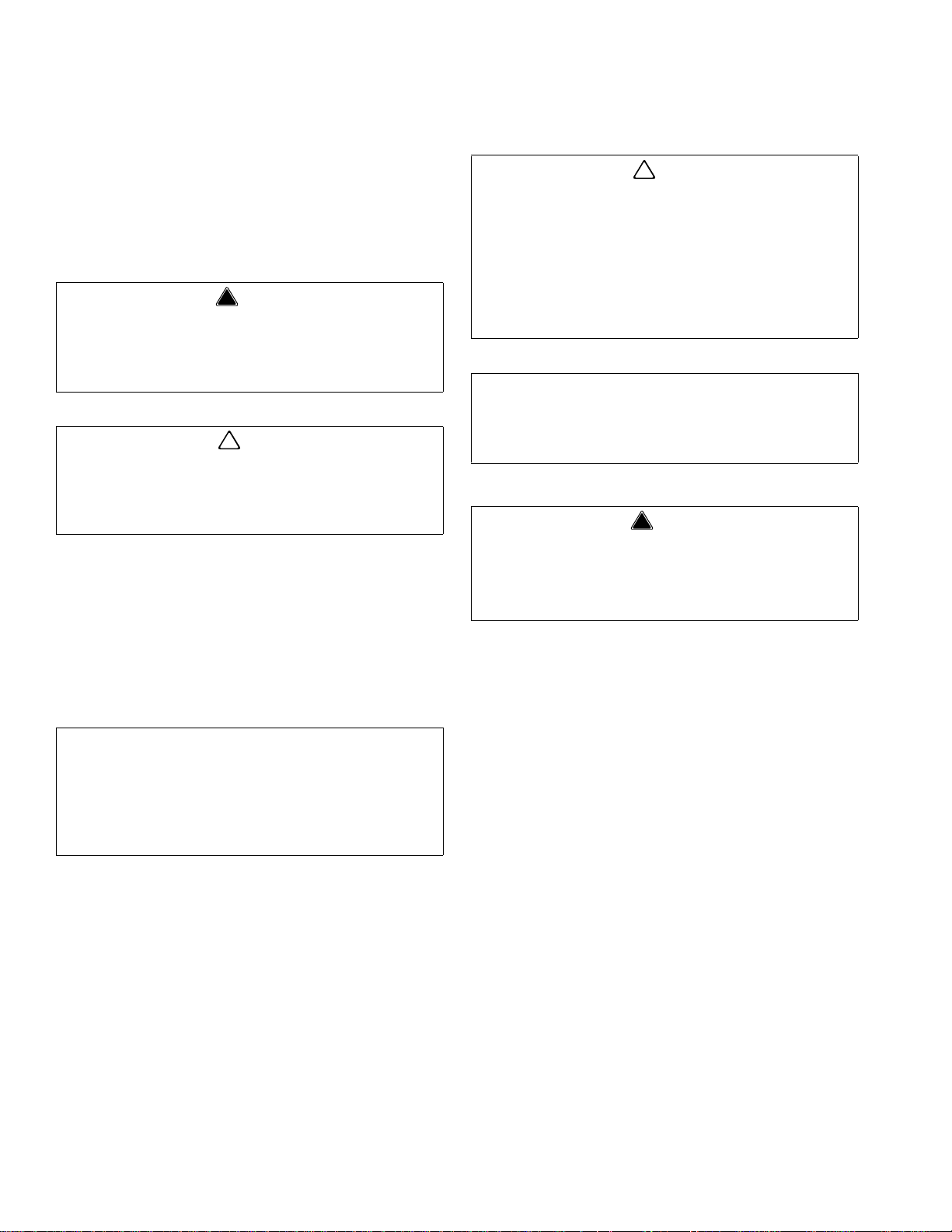
S = Ice Only
SV = Ice/Beverage
NGF = Ice/Beverage
FRP = Ice/Beverage &
Integrated Flavor Shots
i = Intellicarb
QD = Quickdraw
SCI = Ice Crusher
Ice Capacity
Model Prefix
Model Suffix
Model Base
MDH–302– i
Section 1
General Information
Read This Manual
Manitowoc Beverage Equipment (MBE) developed this
manual as a reference guide for the owner/oper ator a nd
installer of this equipment. Please read this manual
before installation or operation of the machine. A
qualified service technician must perform inst allation and
start-up of this equipment, consult Section 5 within this
manual for service assistance.
If you cannot correct the service problem, call your MBE
Service Agent or Distributor. Always have your model
and serial number available when you call.
Your Service Agent ____________________________
Service Agent Telephone Number_________________
Your Local MBE Distributor ______________________
Distributor Telephone Number____________________
Model Number _______________________________
Serial Number ________________________________
Installation Date ______________________________
Unit Inspection
Model Numbers
This manual covers the following models:
Beverage/Ice Dispensers
Flavor Magic, MDH302, MDH402, SV-200, SV -250
HOW TO READ A MODEL NUMBER
Accessories
Thoroughly inspect the unit upon delivery. Immediately
report any damage that occurred during tr ansportation to
the delivery carrier. Request a written inspection report
from a claims inspector to document any necessary
claim.
PERSONAL INJURY POTENTIAL
Do not operate equipment that has been misused,
abused, neglected, damaged, or altered/modified
from that of original manufactured specifications.
Portion control through adjustable dispense time, backlit
dispense nozzle with field-selectable flash sequence,
built-in dispense counter to track individual flavor sales,
POP static cling instruction sheet, easy-to-install preassembled valve/control board module.
MODULE KIT CONTENTS
Switch cover with nozzle, ice chute bracket, cover
mounting bracket, internal nozzle tubing mount, control
board and valve solenoid assembly, nozzle LED
BACK ROOM KIT CONTENTS
BIB rack, BIB syrup pumps (1 for each flavor), low
pressure CO
2 regulator (0-100 PSI), 50 feet of bundled
tubing (1 tube for each flavor)
Part Number 020001199 012/09 1-1
Page 6
General Information Section 1
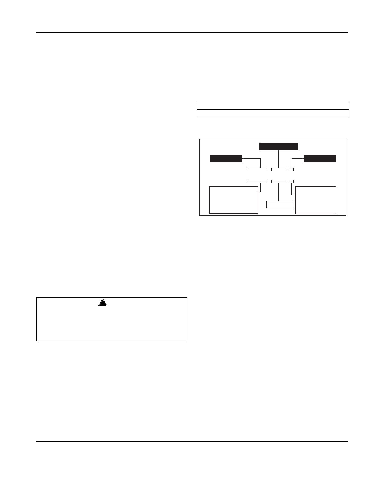
P37SBBKHN (Coca Cola) QCD-II (General Bottler) PCS1 (Pepsi)
020000409 Narrow Lever is used on the following units:
MD & SV-175, MD & SV-200/250 (10 valve), MDH-402 (20 valve)
020000410 Wide Lever is generally used on the following units:
MD & SV-150, MD & SV-200/250 (8 valve), MDH-302/402 (16 valve)
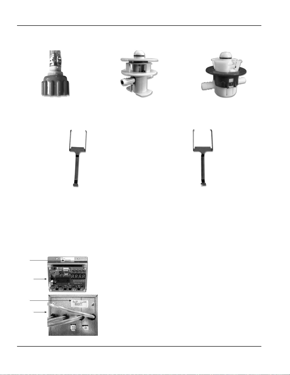
Serial
Control
Board
Remote
Box
Serial
CONNECTORS
Use the following part numbers when ordering additional kits or replacement parts.
SANITARY LEVERS
Use the following part numbers when ordering additional kits or replacement parts.
Serial Number Location
This number is required when requesting information
from your local distributor. The serial number is listed on
the SERIAL NUMBER DECAL affixed to the Flavor
Magic control board bracket.
FLAVOR MAGIC SERIAL NUMBER LOCATIONS
Warranty Information
Consult your local MBS Distributor for terms and
conditions of your warranty. Your warranty specifically
excludes all beverage valve brixing, general
adjustments, cleaning, accessories and related
servicing.
Your warranty card must be returned to MBS to activate
the warranty on this equipment. If a warranty card is not
returned, the warranty period can begin when the
equipment leaves the MBS factory.
No equipment may be returned to MBS without a written
Return Materials Authorization (RMA). Equipment
returned without an RMA will be refused at MBS’s dock
and returned to the sender at the sender’s expense.
Please contact your local MBS distributor for return
procedures.
1-2
Part Number 020001199 012/09
Page 7
General
Important
!
Warning
A
B
C
Section 2
Installation Instructions
These instructions are provided to assist the qualified
installer. Contact your Manitowoc Beverage Systems
Service Agent or call Manitowoc Beverage Systems for
information regarding start-up services.
Failure to follow these installation guidelines may
affect warranty coverage.
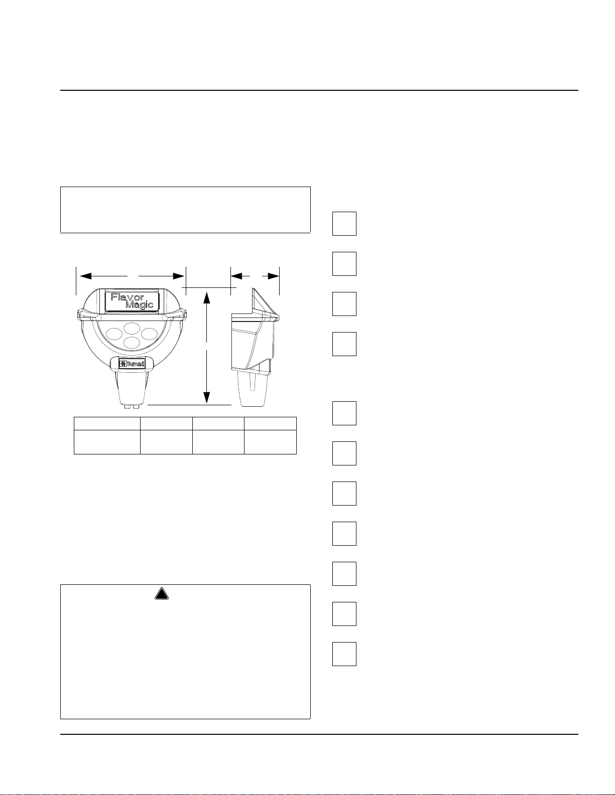
DIMENSIONS
Flavor Magic A B C
Module* 4.66"
(11.84 cm)
5.08"
(12.90 cm)
1.97"
(5.00 cm)
PRE-INSTALLATION CHECKLIST
When installing any system, first make sure the major
components are available. Generally the major
components necessary for an installation are:
Typical BIB System:
B-I-B connectors
B-I-B regulator set
B-I-B rack
B-I-B syrup boxes
Post Mix System:
CO
regulator set
2
Beverage dispenser
ESSENTIAL TOOLS
- Tubing Cutters
Beverage tubing
- Oetiker pliers
- Phillips and slotted screwdriver
tank
CO
- Power drill
2
- Six (6) inch adjustable wrench
- Tape Measure
Carbon Dioxide (CO2) displaces oxygen. Exposure to a
high concentration of CO
are followed rapidly by loss of consciousness and
suffocation. If a CO
in a small area, immediately ventilate the area before
repairing the leak. CO
2
installed in an enclosed space. An enclosed space can
gas causes tremors, which
2
gas leak is suspected, particularly
lines and pumps must not be
2
Carbonator
Stepless (Oetiker) clamps
Chain for CO
tank
2
be a cooler or small room or closet. This may include
convenience stores with glass door self serve coolers. If
you suspect CO
B-I-B pumps and / or CO
Part Number 020001199 012/09 2-1
may build up in an area, venting of the
2
monitors must be utilized.
2
Page 8
Installation Instructions Section 2
!
Warning
Important
!
Warning
!
Warning
Electrical
GENERAL
All wiring must conform to local, state and national codes.
MINIMUM CIRCUIT AMPACITY
The minimum circuit ampacity is used to help select the
wire size of the electrical supply. (Minimum circuit
ampacity is not the beverage/ice machine’s running amp
load.) The wire size (or gauge) is also dependent upon
location, materials used, length of run, etc., so it must be
determined by a qualified electrician.
VOLTAGE
The standard voltage for the Flavo r Magic Module is
24VAC, 0.5 AMP, powered by existing valve transformer
on dispenser.
MINIMUM CIRCUIT AMPERAGE CHART
Due to continuous improvements, this information is
for reference only. Please refer to the dispenser
serial number tag to verify electrical data. Serial tag
information overrides information listed on this page.
Dispenser Voltage/Cycle
Minimum
Circuit Amps
GROUNDING INSTRUCTIONS
Risk of electrical shock. Connect to a properly
grounded outlet only.
This appliance must be grounded. In the event of
malfunction or breakdown, grounding provides a path of
least resistance for electric current to reduce the risk of
electric shock. This appliance is equipped with a cord
having an equipment-grounding conductor and a
grounding plug. The plug must be plugged into an
appropriate outlet that is properly inst alled and grounded
in accordance with all local codes and ordinances.
Improper connection of the equipment-ground ing
conductor can result in a risk of electric shock.
The conductor with insulation having an outer
surface that is green with or without yellow stripes
is the equipment grounding conductor. If repair or
replacement of the cord or plug is neces sary, do
not connect the equipment-grounding conductor
to a live terminal. Check with a qualified electrician
or serviceman if the grounding instructions are
not completely understood, or if in doubt as to
whether the appliance is properly grounded. Do
not modify the plug provided with the appliance —
if it will not fit the outlet, have a proper outlet
installed by a qualified electrician.
MDH-302
MDH-302 w/EM
MDH-402
MDH-402 w/24" EM
MDH-402 w/34" EM 220-240/50 5.0 FLA
SV-200, SV-250 115/60 2.8
115/60 3.5 FLA
220/50, 220/60,
240/50, 240/60
220-240/50 4.5 FLA
220/50, 220/60,
240/50, 240/60
220-240/50
4.0 FLA
(with carb deck)
2-2
1.5
5
Part Number 020001199 012/09
Page 9

Section 2 Installation Instructions
!
Warning
When using electric appliances, basic precautions
should always be followed, including the following:
a. Read all the instructions before using the
appliance.
b. To reduce the risk of injury, close
supervision is necessary when an
appliance is used near children.
c. Do not contact moving parts.
d. Only use attachments recommended or
sold by the manufacturer.
e. Do not use outdoors.
f. For a cord-connected appliance, the
following shall be included:
• Do not unplug by pulling on cord. To
unplug, grasp the plug, not the cord.
• Unplug from outlet when not in use and
before servicing or cleaning.
• Do not operate any appliance with a
damaged cord or plug, or after the
appliance malfunctions or is dropped or
damaged in any manner. Contact the
nearest authorized service facility for
examination, repair, or electrical or
mechanical adjustment.
g. For a permanently connected appliance —
Turn the power switch to the off position
when the appliance is not in use and before
servicing or cleaning.
h. For an appliance with a replaceable lamp —
Always unplug before replacing the lamp.
Replace the bulb with the same type.
i. For a grounded appliance — Connect to a
properly grounded outlet only. See
Grounding Instructions.
Part Number 020001199 012/09 2-3
Page 10

Installation Instructions Section 2
Flavor 1
Flavor 2
Flavor 3
2 x 4 BIB Rack
Flavor 5
Flavor 6
Flavor 7
Flavor 4 Flavor 8
Flavor 1
Flavor 2
Flavor 3
1 x 3 BIB Rack
Flavor 1
Flavor 2
Flavor 3
2 x 3 BIB Rack
Flavor 4
Flavor 5
Flavor 6
BIB Rack Configurations
Flavor
Magic
Module
SET REGULATOR
20 to 30 PSI
Valve 1
Pump
1
Pump
2
Pump
3
Pump
4
Flavor 1
Flavor 2
Flavor 3
1 x 4 BIB Rack
Flavor 4
CO
2
Supply
Valve 2
Recommended Plumbing
GENERAL
The Flavor Magic Module is compatible with MDH & SV
units. See the appropriate section for instructions on
attaching the module assembly to the unit.
CAPACITIES SPECIFICATIONS CHART
Module Valves Flow Rate
Flavor Magic 1 per flavor,
up to 4 flavors
Variable, 0.5 oz/
sec nominal
Dispense
Time
0.2 - 10
seconds,
adjustable in
0.2 second
increments
Dispenser Incoming Plain
Water Pressure
Ambient Temperature 40 °F
B-I-B (Secondary) 75 psi or according to line run
Flavor Magic Regulator 20 psi MAX or according to line run
MIN. MAX
40 psi dynamic 70 psi static
105°F
(4°C)
(41°C)
2-4
Part Number 020001199 012/09
Page 11

Section 2 Installation Instructions
Important
Important
Step by Step Aftermarket & Integrated Installations
PRE-INSTALLATION
MDH Aftermarket installations, measure the
merchandiser depth from the valve mount cap to the
outside. If the depth is approximately 5 inches, STOP.
This version of Flavor Magic is not compatible with the
merchandiser frame. Contact the factory to order a
compatible merchandiser frame. (See Part s Manual)
1. Disconnect electrical power to ice drink dispenser.
2. Remove translite, lamps and splash panel from
dispenser work area.
3. Remove “Push for Ice” lever from rocking chute
where the Flavor Magic is to be installed.
4. Remove the caps from the valves on either side of
the rocking chute.
Integrated MDH & SV installations, additional
components must be field installed and are found in
a box shipped with the dispenser. 0-30 CO
regulator, CO2 and Flavor Magic syrup lines, fittings,
and clamps must be field supplied.
MDH-302/402 MODULE
Aftermarket
1. Remove the merchandiser or carefully lift up the
merchandiser approximately 1 inch on the side
where the Flavor Magic is to be installed.
2. Insert the LH mounting bracket, 020000896, under the
merchandiser at a 45 deg. angle.
4. Insert the RH mounting bracket, 020000897, under the
merchandiser at a 45 deg. angle.
2
5. Rotate the bracket vertically hooking the back flange over
the valve mounting cap and passing the front plate
through the opening in the merchandiser in front of the
rocking chute.
6. Carefully lower the merchandiser into place.
3. Rotate the bracket vertically hooking the back flange over
the valve mounting cap and passing the front plate
through the opening in the merchandiser in front of the
rocking chute.
Part Number 020001199 012/09 2-5
Page 12

Installation Instructions Section 2
!
Caution
Module
Thumbscrew
Tubing
7. Route the tubing and ribbon cables from the module
assembly between the opening in the merchandiser and
mounting brackets.
DO NOT PINCH TUBING BETWEEN CHUTE PLA TE
AND MERCHANDISER
12. Check that the mounting brackets are not rubbing the
rocking chute. Lift the merchandiser and slide the
bracket assembly left or right to allow the brackets to
clear the chute.
13. Replace “Push for Ice” lever in lower position holes
on rocking chute or replace with sanitary lever as
8. Align the channels on the center bracket, 020000898,
inside the channels on the LH and RH mounting
brackets.
required by local codes. Check to assure door lock
is functioning properly.
SV-150/175/200/250 MODULE
Aftermarket
1. Hook the flanges on the module assembly,
020001154, over the valve mounting cap on either
side of the rocking chute. Center the assembly, so
there is clearance between the chute and brackets.
2. Loosen, but do not
remove, the thumb screws on
either side of the module assembly. Pull the plastic
module forward.
9. Loosely fasten the thumbscrews on both sides of the
bracket assembly
10. Push the plastic module housing against the
merchandiser frame. Firmly tighten the thumb screws.
1 1. Secure the tubing through the plastic clips on the
mounting brackets.
3. Make sure the tubing is through the plastic cl ip s and
loops toward the bottom plate, allowing the module
to slide forward and back w/o straining the tubes.
4. Replace “Push for Ice” lever in lower position holes
on rocking chute or replace with sanitary lever and
check to assure door lock is functioning properly.
2-6
Part Number 020001199 012/09
Page 13

Section 2 Installation Instructions
6 Pin
Connector
Important
Remote Box Tubing & Connectors
Factory Integrated Valve & Line Locations
SYRUP & CO2 LINES
Remote Box
(For SV-150/175 & MDH-302/402 with Crusher)
5. Identify the remote box part# 020000508. Select a
location for the box close to the dispenser, but away from
patron access. The box must be within 6-8 feet of the
back of the unit. Ideal locations include behind the unit, or
in a cabinet below the unit. The box may be mounted in
any orientation.
6. Disconnect the valve harness from the load side of the
transformer inside the unit’s electrical box. Connect the
24V power harness, 020000590 to the load side of the
transformer. Connect the valve harness to the
connector on 020000590. (see wiring diagram)
7. Route the 24V power harness, 020000590, behind the
splash panel and below the unit to the r emote box. Plug
the harness into the two pin connector on the box.
8. Connect the control harness, 020000585, to the
connectors on the module for the LED and touch pad.
9. Route the control harness, 020000585, behind the
splash panel and below the unit to the r emote box. Plug
the harness into the six pin connector on the box.
Tubing
12. Route the four (4) line bundle tubing from the back room
to dispenser behind the valve mounting plate to the
mounted valve assembly or remote box depending on
your installation, do not
attach yet. Remote box
installations, place the 1/8" plastic tubing connectors,
020001327 firmly into the four (4) line bundle tubing.
Use caution so wires that power post mix valves are
not broken or dislodged.
NOTE: Cut any excess length from the end of the tubing
connected to the Flavor Magic module but leave enoug h
slack in tubing to reach the approximate location where
valve assembly or remote box will be mounted.
NOTE: MDH installations using Flavor Magic modules
on both sides dispensers, add tees and additional tubing
for 3 or 4 flavor dual module kits and route to opposite
side of dispenser. If same flavors are used on both
sides, use ¼” by ¼” by ¼” tees (.635 cm x .635cm x .635
cm) to deliver syrup to both sides.
13. Route ¼” (.635 cm) syrup lines (field supplied) from BIB
rack containing in back room to dispenser . The number of
lines will be determined by the number of flavors used
.
10. Check that the wiring length is sufficient to mount
the box in the desired location.
1 1. Remove the cover from the remote box by removing the
two 8-32 screws and pulling upward on the cover .
Part Number 020001199 012/09 2-7
Page 14

Installation Instructions Section 2
NOTE: ¼” (.635 cm)
white nylon washers are
included in the fitting
package and must be
used to prevent syrup
leaks in this area.
IMPORTANT
Set regulator to a
maximum of 20 Psi
14. Attach four (4) bundle syrup lines, nuts, washers, and
barbed fittings to the Flavor Magic valve inlets. Be sure
NOT to over tighten nuts.
19. Place BIB syrup on BIB rack.
20. Attach BIB connectors to flavor syrup boxes.
NOTE: BIB connectors vary with syrup manufacturer.
Assure that correct connector is used.
21. Turn on CO
22. Check syrup and CO
2 supply and adjust to twenty (20) PSI (1 bar).
2 connections for leaks. Return to
dispenser unit
15. Mount valve assembly plate with the two (2) #10 x¾”
(.953 cm) sheet metal screws provided in a convenient
spot near the rocking chute, or place remote box in final
location if doing a remote box installation.
16. Route the vinyl lines to the valve assembly or remote box
and cut lines to fit neatly over the valve outlets.
Back room Tasks
17. Turn off CO
2 supply in back room.
18. Route 1/4" (673 cm) beverage tubing from CO
to CO
2 regulator on BIB rack and secure with proper
Oetiker clamp.
2 supply
Control Board
23. Connect the control board harness to the circuit
board and to the electrical connectors from the
touchpad cover and LED.
24. Connect the 24V power harness from the transformer to
the circuit board.
25. Restore power to unit. (Blue LED light(s) should be lit).
26. Assure that control board readout is in dispense
mode (“- - - -”)
2-8
Part Number 020001199 012/09
Page 15

Section 2 Installation Instructions
Module
Thumbscrew
Merchandiser
FINALIZING INSTALLATION
27. Purge air from syrup lines by utilizing the purge/sanitize
mode until syrup is running freely. Adjust dispense time if
desired. (See Control Board programming)
28. Return control board to dispense mode by pressing
the program button.
29. Test each flavor for proper dispensing by placing a
cup under the nozzle and dispense one at a time by
pressing each flavor icon. Dispense rate is preset at
one-half (1/2) oz (15 ml) per one (1) secon d or
dispense. Additional setup is normally not required
for proper operation. (See the Operation section for
programming the dispense time.)
30. Neatly arrange and tie up wires
. Route the tubing and
wiring away from the rocking chute mechanism. Secure
the tubing and wiring using the peel and stick plastic clips,
0905403, provided.
33. Assemble the black, plastic bottom piece with
cutout, 02000592, to the merchandiser assembly.
Push the plastic piece all the way down onto the
translite. Tighten the 3, #10 screws removed from
the original merchandiser bottom.
34. Attach the merchandiser assembly to the machine.
35. Push the flavor magic module inward against the
merchandiser. Tighten the thumb screws on with
either side of the module assembly.
31. Replace splash panel, lamps and merchandiser cover.
SV Installations
32. SV Installations, remove the black plastic bottom
piece from the merchandiser assembly by removing
the 3, #10 screws.
NOTE: To remove the merchandiser, loosen but do not
remove the thumbscrews and slide the module outward
away from the merchandiser.
MDH & SV Installations
36. Replace the valve caps
37. Place the flavor labels on the cover pad according to the
desired flavor line up.
38. Carefully position the clear adhesive decal overlay over
the flavor labels and secure to pad.
39. Review basic Flavor Magic operation, flavor BIB
changing, and periodic cleaning and maintenance
with customer.
Part Number 020001199 012/09 2-9
Page 16

Installation Instructions Section 2
MDH-302 SV-250
Important
Starting Your Beverage System & Dispenser
Upon completion of the beverage dispenser and / or
system installation, all tubing, dispenser, and system
components must be cleaned and sanitized prior to use.
NOTE: At installation, equipment, dispensers, and
tubing get moved through many environment s, dirt, dust,
chases, insulation, drywall, etc. It is an important
procedure and best practice to address cleaning to
deliver the best quality drink to your custome r.
Clean and sanitize the water and syrup circuits according
to instructions provided in this manual. Clean and
sanitize the dispenser components according to
instructions provided in this manual. Seal to counter top
when no legs are used with the unit. Consult and use
local health codes if a discrepancy occurs between this
manual and your local health codes.
2-10
Part Number 020001199 012/09
Page 17

Section 3 Operation
Blue LED
Flavor Selection
Touch Pad
Nozzle
Module Cover
Section 3
Operation
General System Overview
COMPONENT IDENTIFICATION
RACKING
A rack (or shelf) system affords systematic placement and
complete usage of the beverage paid for. The B-I-B rack
allows the boxes to lay properly for syrup dispersal. Please
check with your B-I-B syrup supplier. Some boxes must be
slightly tilted down, while others may be in virtually any
position.
B-I-B
The Bag-In-Box system refers to a plastic disposable bag.
The B-I-B normally contains 5 gallons of syrup, however
some locations offer 2-1/2 gallon B-I-B unit s. This plastic bag
is then held inside a cardboard or other container. B-I-B
systems are for post-mix applications only .
PUMPS
The syrup in a B-I-B system is delivered to the beverage
system through gas operated pumps. These pump s extract
the syrup out of the bags, forcing the syrup throughout the
system.
Part Number 020001199 012/09 3-1
Page 18

Operation Section 3
PROGRAM
BUTTON
LED
DISPLAY
1
2
3
4
Programming Modes
To exit the program mode at any time hold the program
button for >3 seconds and the controller will switch to the
dispense mode. The program mode can only be accessed
by pressing the program button during the first five seconds
of initial power up.
PROGRAM DISPENSE TIME
1. The program mode is used to adjust the dispense time. To
access the Program Mode, disconnect power to the control
board, wait ten (10) seconds and reconnect power.
2. Press the program button one time on the control board
during the first five (5) seconds after power is applied.
3. The LED display will show “P r o”. T o check the current
dispense time, press the corresponding flavor button on
the touchpad and the time will be displayed on the LED
(Example “1.0”). a. T o increase the time (+) by twotenths (0.2) second increments press flavor button 1 (far
left button). To decrease the time (-) by two-tenths (0.2)
second increments press flavor button 3 (far right
button). The default setting is one (1.0) second.
PURGE/SANITIZE
1. Purge/Sanitize mode allows the user to purge air from
the syrup lines during initial start-up. The second
function of this mode is to energize the valves to move
sanitizer through all syrup lines automatically.
2. Enter the Purge/Sanitize Mode by press the program
button until “P – S” is displayed.
3. Pressing flavor button 1 (far left button) will activate a
sequenced four (4) second dispense that st arts with
flavor 1 then to flavor 2 etc. The valves will continue to
cycle for 15 minutes or until the program button is
pressed once.
DISPENSING MODES
Normal Dispense
With power applied to the control board, it will automatically
start in dispense mode after a five (5) second delay. The LED
display will count down from four (4) to zero (0) and then show
“- - - -” while in dispense mode. Simply pressing the desired
flavor on the touchpad dispenses Flavor Magic.
3-2
Flavor Counter
The flavor counter tracks the number of flavor shots
dispensed per flavor. To access Flavor Counter Mode, press
the program button on the control board once for at least
three (3) seconds. The LED display will show “C n t”. In the
count mode the Flavor Magic module will not dispense.
Check the number of dispenses for any flavor by pressing
the corresponding touchpad button. To check another flavor
press the program button once and then the corresponding
flavor button on the touchpad. To return to dispense mode
press the program button until the LED display shows “- - - -”.
CHANGING NUMBER OF ACTIVE FLAVORS
To line up flavors with valves, note that valve outlets number
from left to right 1…2…3…4. Touch pad flavor tab is
numbered as shown below . Connect vinyl tube from outlet 1
and dispense with flavor tab 1, etc..
The current Flavor Magic control board is set up in the 4
flavor default mode. This mode will handle all dispensing
situations whether 3 or 4 flavors are used. Some early
boards were set up as default in the 3 flavor mode. If the
customer desires to add another flavor for a total of 4,
proceed as follows:
1. Power down the circuit board by disconnecting the 24
volt connector in the lower left hand side of the board.
“24V AC” is imprinted on the boar d next to the pin
connection.
2. Wait a minimum of 10 seconds.
3. Power up the board by connecting the 24 volt connector.
4. IMMEDIATELY (within 5 seconds) press and hold the
“PROG” button down.
5. After a few seconds, the number “4” will appear on the
display .
6. Release the “PROG” button. The board will cycle the
display from “Pro” to “4……3……2……1……0” and
then to “- - - -”.
7. The circuit board is now enabled to dispense the 4th
flavor. The 4th flavor button is th e top middle button.
Part Number 020001199 012/09
Page 19

Section 3 Operation
1
2
3
4
TOUCH PAD LED
8. A flavor tab for the 4th flavor will have to be added to the
touch pad. To do this, obtain one (1) P/N 5030780 20
flavor decal pad. Remove the P/N 5031579 decal
overlay and add the 4th flavor tab as well as replace any
flavor tabs which came off when removing th e decal
overlay.
NOTE: Position of 4th flavor on the touch pad in the
picture and placed tab where indicated.
9. Obtain a new P/N 5031579 decal overlay and place
over the tabs.
If the customer decides to go back to 3 flavors, it will not be
necessary to change the board back to 3 flavors. However, it
can be done by following steps 1 through 6 above. The
number “3” will appear on the display. Then disconnect the
number “4” syrup from the system, remove the 5031579
decal overlay , remove the flavor t ab “4” and replace the
5031579 decal overlay .
NOTE: It would be a good idea to have an additional P/N
5030780 in case flavor tabs are damaged in the process.
TOUCH P AD LED
2. Enter the Flash mode by pressing the program button
until a flashing “- - - -” is displayed. Pressing flavor button
1 (far left button) will switch from “Off” (default) to “On”.
The LED will now flash.
3. T o change back to the default simply press flavor button
1 again and the display should read “Off”.
4. Press program button to exit to the next program
function.
TIME DELA Y AFTER DISPENSE
1. A time delay can be programmed into the control board
which will prevent the system from dispensing another
flavor for a period of from 0 to 10 seconds following a
dispense. The default is 0 seconds.
2. Enter the Time Delay mode b y pressing the p rogram
button until “d L A Y” is displayed. To check the current
delay time press any flavor button one time and the
current value will be displayed. To increase the time (+)
by 1.0 second increments press flavor button 1 (far left
button).
3. To decrease the time (-) by 1.0 second increments
press flavor button 3 (far right bu tton). When done move
on to another programming mode or if you are finished
return the control board to the dispense mode by
pressing the program button and holding for 3 seconds
or until the LED displays 0.
The blue LED on the touch pad can be set to one (1) of two
(2) display modes:
Steady LED
1. Steady illumination is the default mode, the LED will
remain on steady until dispense is activated. The light
will flash only when product is being dispensed. In this
mode, the control board display will read “Off”.
2. To program the steady LED, press the program button
until a flashing “- - - -” is displayed. Press flavor button 1
(far left button) to switch from “On” to “Off”, "Off" is the
default. The LED will now stay on steady.
3. Press program button to exit to the next program
function.
Flashing LED
1. In Flash mode the LED will turn on for ½ second and off
for ½ second.
Part Number 020001199 012/09 3-3
Page 20

Operation Section 3
Control Logic Matrix
3-4
Part Number 020001199 012/09
Page 21

Section 4 Maintenance
!
Warning
Important
Important
!
Warning
!
Warning
Section 4
Maintenance
PREVENTATIVE MAINTENANCE
Proper care of the Flavor Magic is a vital p art of keeping your
unit in top condition. Following the guidelines below will
assist you in continued trouble free operation. Contact MBE
at 1-800-367-4233 for more information about our ProActive
Maintenance Program.
Electric Shock Hazard
Unplug unit before servicing or cleaning.
Under normal operating conditions, periodic
cleaning is minimal but absolutely necessary
1. Conduct daily maintenance of the unit. Clean the nozzle
and retainer area in order to prevent syrup buildup in this
area by doing the following:
a. Fill a small cup with warm to hot water .
b. Immerse the nozzle area fully by drawing the cup
up and around the nozzle.
c. Allow syrup to dissolve into the water. Change the
water several times to assure the syrup is
adequately removed.
d. Discard water.
2. After each removal from an empty bag and prior to
placing connector on new bag clean BIB connectors to
prevent syrup residue by doing the following:
a. Prepare a bucket of warm to hot water .
b. Submerge connector in water until syrup residue is
dissolved.
c. Place connector on new bag.
d. Discard water.
CLEANING CHECKLIST
BEVCLEAN™ PROCESS
To efficiently clean entire dispensing circuit:
1. Hook up BevClean™ system per BevClean™
instructions.
2. Set Control Board to “Purge” mode. Press Flavor 1
tab to initiate “Purge” Cycle to draw BevClean™ into
system. Allow cleaner to remain in system for five
(5) minutes.
3. Disconnect BevClean™ system and reconnect
disconnects to BIB’s.
4. Set Control Board to “Purge” mode. Press Flavor 1
tab to initiate “Purge cycle to completely remove
BevClean™ from syrup lines and vinyl tubing. (See
PURGE/SANITIZE in the Programming Modes
section)
5. Set Control Board to “Purge” mode. Press Flavor 1
tab to initiate “Purge cycle completely fill system with
syrup.
6. Restore Control Board to “DISPENSE” mode.
Dispense and discard sufficient samples to assur e
all BevClean™ is removed from system.
CONVENTIONAL CLEAN/SANITIZE METHOD
When changing syrup boxes, immerse connector in
warm water (100° F, 38° C - maximum temperature) to
remove syrup residue. RECOMMENDED SANITATION
INTERV AL IS EVER Y 90 DAYS
Flush sanitizing solution from syrup system. Residual
sanitizing solution left in system could create a health hazard.
•Check CO
primary regulator gauge will point to a shaded area that
reads “Low CO
• Check syrup supply.
• Clean drain pan, grid, and splash pane l.
• Clean the nozzles.
Part Number 020001199 012/09 4-1
supply . If CO2 supply is low, an arrow on the
2
” or “Change CO2 Cylinder.”
2
When using cleaning fluids or chemicals, rubber gloves
and eye protection must be worn.
Sanitize the beverage system at initial start-up as well as
regularly scheduled cleaning. The drain pan must be in
place under soda valves, to carry away detergent and
sanitizing agents that will be flushed through valves.
Page 22

Maintenance Section 4
!
Caution
BAG-IN-BOX SYSTEM SANITATION
The procedure below is for the sanitation of one syrup circuit at a time. Repeat to sanitize additional circuits.
Y ou will need the following items to clean and sanitize the
Bag-in-Box (BIB) beverage system:
• Three (3) clean buckets
• Plastic brush or soft cloth
• Mild detergent
• Unscented bleach (5% Na CL O) or
Commercial sanitizer
• Bag-In-Box bag connector
1. Prepare the following in the buckets:
• Bucket 1 — warm to hot tap water for rinsing.
• Bucket 2 — mild detergent and warm to hot water .
• Bucket 3 — mix a solution of unscented bleach (5%
Na CL O) or commercial sanitizer and
warm to hot water. Mixture should
supply 100 PPM available chlorine (1/4
oz. bleach to 1 gallon water).
2. Disconnect the “syrup-line side” of the BIB connector.
3. Rinse connector with warm tap water .
4. Connect syrup connector to BIB connector and
immerse both into Bucket 1. A “bag-side” connector
can be created by cutting the connector from an empty
disposable syrup bag.
5. Set the Control Board to the “Purge” mode by
pressing flavor button 1 (far left button) to activate a
sequenced four (4) second dispense that starts with
flavor 1 goes to flavor 2 etc. (The valves will
continue to cycle for 15 minutes or until the program
button is pressed once). (See PURGE/SANITIZE in
the Programming Modes section)
13. Remove the nozzle(s) and retainer(s) from the Flavor
Magic Module(s) and scrub them with a plastic brush or
cloth using the detergent solution.
14. Soak plastic tubing ends at retainer in sanitizing solution
for fifteen (15) minutes.
15. Soak nozzle(s) and retainer(s) in sanitizer for fifteen (15)
minutes.
16. Replace nozzle(s) and retainer(s).
17. Connect Bucket 1 to system.
18. Draw rinse solution by activating “Purge” mode as
described in step 5 and operating valves until rinse water
is dispensed.
19. Attach syrup connectors to BIB’s.
20. Draw syrup by activating “Purge” mode as described in
step 5 and operate valves until only syrup is dispensed.
21. Place Control Board in dispense (“- - - -”) mode and
operate each flavor three (3) times into a disposable cup.
22. Discard the cup and contents.Shipping, Storage and
Relocation
Before shipping, storing, or relocating this unit, syrup
systems must be sanitized. After sanitizing, all liquids
(sanitizing solution and water) must be purged from the
unit. A freezing environment causes residual sanitizing
solution or water remaining inside the unit to freeze,
resulting in damage to internal components.
6. Draw rinse water through system until clean water is
dispensed.
7. Connect Bucket 2 to system.
8. Draw detergent solution by activating “Purge” mode as
described in step 5 and operating valves until detergent
solution is dispensed.
9. Allow detergent solution to remain in the system for 5
minutes.
10. Connect Bucket 3 to system.
1 1. Draw sanitizing solution by activating “Purge” mode as
described in step 5 and operating valves until sanitizing
solution is dispensed.
12. Allow sanitizer to remain in system for fifteen (15)
minutes.
4-2
Part Number 020001199 012/09
Page 23

Section 5 Before Calling for Service
Section 5
Before Calling for Service
Checklist
If a problem arises during operation of your dispenser, follow the checklist below before calling service. Routine
adjustments and maintenance procedures are not covered by the warranty.
Problem Possible Cause
Flavor Magic syrup does not dispense when flavor button is
depressed.
No power to control board. Check power supply at transformer — 24 VAC.
Control board inoperative. Assure that Control Board is set to dispense – “ _ _ _ _ ” .
If flavor syrup does not shut off. Check for stuck solenoid.
Syrup supply depleted.
CO2 supply depleted.
BIB disconnect loose or packed with dried syrup residue.
Check CO2 regulator for proper setting — 20 PSI (1 Bar).
Check CO
Check syrup line for kinks.
BIB pump inoperative.
Valve solenoid inoperative.
Vinyl tubing off at nozzle or at solenoid.
Vinyl tubing plugged with syrup at nozzle or at solenoid.
Check connector to transformer and Control Board Flavor Shot.
Check wiring for loose connections or open wires.
Check for damage to Control Board.
2 lines for kinks.
Part Number 020001199 012/09 5-1
Page 24

© 2008 Manitowoc
Continuing product improvements
may necessitate change of
specifications without notice.
Part Number 020001199 012/09
Manitowoc Beverage Equipment
Sellersburg, IN 47172, USA
Ph: 812-246-7000 Fax: 812-246-7024
Visit us online at: www.manitowocfsg.com
2100 Future Drive
 Loading...