


IMS-4000
Table of contents
 Loading...
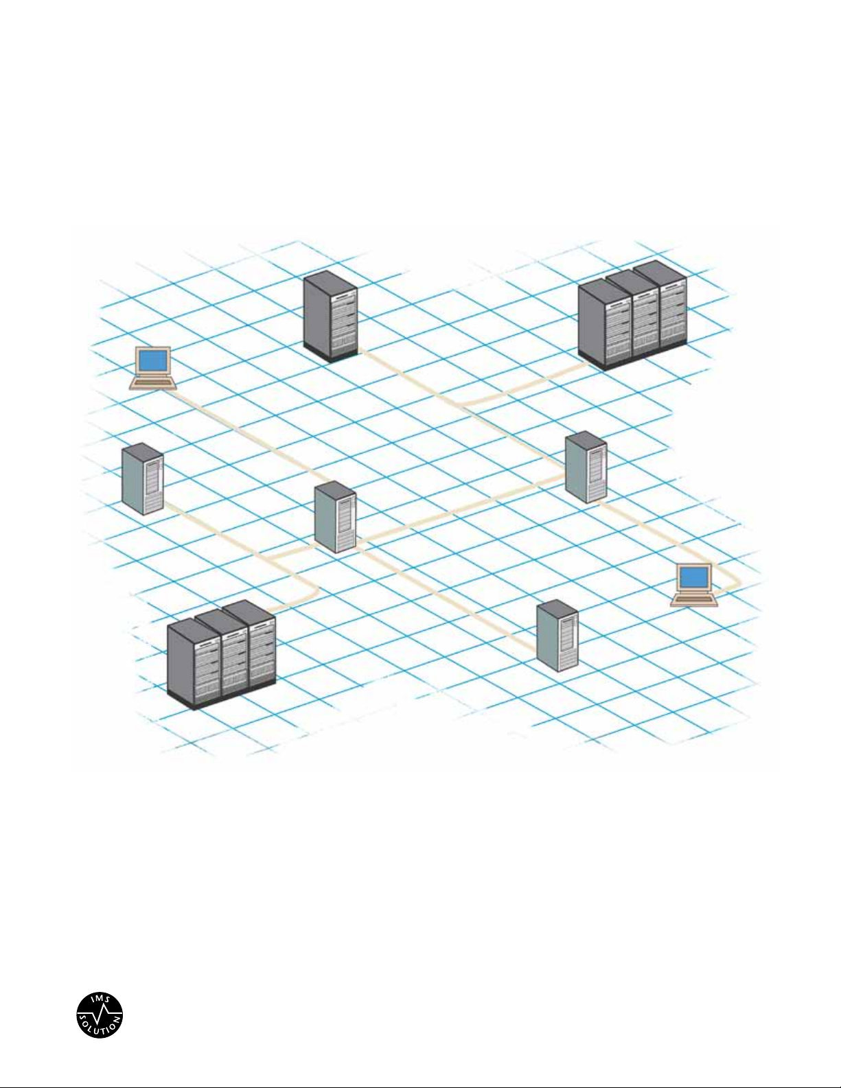
IMS–4000
™
SENSAPHONE
®
LIT-0064
SENSAPHONE
®
IMS-4000
Infrastructure Monitoring System
User’s Manual


USER’S MANUAL
VERSION 2.6

ii
Every effort has been made to ensure that the information in this document is complete, accurate and up-to-
date. Sensaphone assumes no responsibility for the results of errors beyond its control. Sensaphone also can-
not guarantee that changes in equipment made by other manufacturers, and referred to in this manual, will not
affect the applicability of the information in this manual.
Copyright © 2003 by Sensaphone.
Second Edition, version 2.6, August 2011
Written and produced by Sensaphone
Please address comments on this publication to:
SENSAPHONE
®
901 Tryens Road
Aston, PA 19014
Sensaphone is a registered trademark of Phonetics, Inc.

iii
Important Safety InStructIonS
Your IMS-4000 has been carefully designed to give you years of safe, reliable performance. As with all electrical equipment,
however, there are a few basic precautions you should take to avoid hurting yourself or damaging the unit:
• Read the installation and operating instructions in this manual carefully. Be sure to save it for future reference.
• Read and follow all warning and instruction labels on the product itself.
• To protect the IMS-4000 from overheating, make sure all openings on the unit are not blocked. Do not place on or near
a heat source, such as a radiator or heat register.
• Do not use your IMS-4000 near water, or spill liquid of any kind into it.
• Be certain that your power source matches the rating in the specifications of this manual. If you’re not sure of the type of
power supply to your facility, consult your dealer or local power company.
• Do not allow anything to rest on the power cord. Do not locate this product where the cord will be abused by persons
walking on it.
• Do not overload wall outlets and extension cords, as this can result in the risk of fire or electric shock.
• To reduce the risk of electric shock, the power supply cord for the IMS-4000 Host must have a grounded lug.
• The IMS-4000 Host power supply cord must be used in accordance with applicable UL/CSA/EN/IEC standards, and
must meet the conductor size and length terms of the above-mentioned standards.
• All IMS-4000 components (Host, Node, PowerGate and PowerGate2) must be plugged into a grounded outlet.
• Never push objects of any kind into this product through ventilation holes as they may touch dangerous voltage points
or short out parts that could result in a risk of fire or electric shock.
• To reduce the risk of electric shock, do not disassemble this product, but return it to Sensaphone Customer Service, or
another approved repair facility, when any service or repair work is required. Opening or removing covers may expose
you to dangerous voltages or other risks. Incorrect reassembly can cause electric shock when the unit is subsequently
used.
• If anything happens that indicates that your IMS-4000 is not working properly or has been damaged, unplug it immedi-
ately and follow the procedures in the manual for having it serviced. Return the unit for servicing under the following
conditions:
1. The power cord or plug is frayed or damaged.
2. Liquid has been spilled into the product or it has been exposed to water.
3. The unit has been dropped, or the enclosure is damaged.
4. The unit doesn’t function normally when you’re following the operating instructions.
• Avoid using a telephone (other than a cordless type) during an electrical storm. There may be a remote risk of electric
shock from lightning.
• Do not use the telephone to report a gas leak in the vicinity of the leak.
• To reduce the risk of fire or injury to persons, read and follow these instructions:
1. Use only the specified type and size batteries.
2. Do not dispose of the batteries in a fire. The cell may explode. Check with local codes for possible special disposal
instructions.
3. Do not open or mutilate batteries. Released electrolyte is corrosive and may cause damage to the eyes or skin. It
may be toxic if swallowed.
4. Exercise care in handling batteries in order not to short the battery with conducting materials such as rings, brace-
lets, and keys. The battery or conductor may overheat and cause burns.
5. Remove main power and telephone connections before replacing the battery.

IMS-4000 Manual
iv
WIchtIge SIcherheItShInWeISe
Ein wesentlicher Aspekt bei der Entwicklung Ihres IMS-4000 war die Gewährleistung eines sicheren und zuverlässigen
Betriebs über viele Jahre hinweg. Wie bei allen elektrisch betriebenen Einrichtungen sollten Sie jedoch auch hier einige
grundlegende Vorsichtsmaßnahmen beachten, um Schäden am Gerät und Verletzungen zu vermeiden:
• Die Installations- und Betriebsanweisungen in diesem Handbuch aufmerksam und vollständig durchlesen. Das
Handbuch für den Fall aufbewahren, dass Sie es in Zukunft noch mal benötigen.
• Alle am Produkt angebrachten Etiketten mit Warnungen und Vorschriften lesen und beachten.
• Um das IMS-4000 vor Überhitzung zu schützen, niemals die Lüftungsöffnungen des Geräts blockieren. Das Gerät nicht
auf oder in der Nähe einer Wärmequelle (Heizkörper, Heizschacht) aufstellen.
• Das IMS-4000 nicht in unmittelbarer Umgebung von Wasser verwenden. Keine Flüssigkeiten in das Systemgehäuse
gelangen lassen.
• Sicherstellen, dass die verwendete Stromquelle derjenigen entspricht, die in den technischen Daten dieses Handbuchs
angegeben ist. Wenn Sie nicht wissen, welche Art von Stromquelle in Ihrer Anlage zum Einsatz kommt, wenden Sie
sich an Ihren Händler oder den örtlichen Energieversorger.
• Keine Gegenstände auf dem Netzkabel abstellen. Dieses Produkt nicht so aufstellen, dass Personen auf das Netzkabel
treten und es beschädigen können.
• Netzsteckdosen und Verlängerungskabel nicht überlasten. Es besteht Feuer- und Stromschlaggefahr.
• Um das Stromschlagrisiko zu senken, für den IMS-4000-Host ausschließlich ein Netzkabel mit Schutzkontaktstecker
verwenden.
• Das Netzkabel des IMS-4000-Hosts ist in Übereinstimmung mit den anwendbaren UL-/CSA-/EN-/IEC-Normen bzw.
den entsprechenden in Ihrem Land gültigen Normen zu verwenden. Die Vorschriften der genannten Normen in bezug
auf die Abmessungen und Längen von Leitern sind einzuhalten.
• Alle IMS-4000-Komponenten (Host, Knoten, PowerGate und PowerGate2) müssen an eine geerdete Netzsteckdose ange-
schlossen werden.
• Niemals Gegenstände welcher Art auch immer durch die Lüftungsöffnungen in das Gehäuse des Produkts stecken, da
die Gefahr besteht, dass spannungsführende Teile berührt oder Kurzschlüssen verursacht werden, die zu einem Brand
oder Stromschlag führen können.
• Um das Stromschlagrisiko zu senken, das Produkt nicht zerlegen, sondern bei erforderlichen Wartungs- oder
Reparaturarbeiten zum Sensaphone-Kundendienst oder zu einer anderen zugelassenen Werkstatt geben. Beim Öffnen
oder Entfernen von Abdeckungen und Blenden bestehen verschiedene Gefahren, wie etwa die Möglichkeit des
Kontakts mit gefährlichen Spannungen. Ferner kann ein unsachgemäßer Zusammenbau zu einem Stromschlag führen,
wenn das Gerät anschließend in Betrieb genommen wird.
• Wenn Sie feststellen, dass Ihr IMS-4000 nicht einwandfrei funktioniert oder beschädigt wurde, das Gerät umgehend
vom Netz trennen und die im Handbuch stehende Anleitung zur Kontrolle und Reparatur befolgen.
Das Gerät unter folgenden Umständen in Reparatur geben:
1. Netzkabel oder -stecker sind verschlissen oder beschädigt.
2. Flüssigkeit ist in das Gehäuse eingedrungen, oder das Produkt ist mit Wasser in Berührung gekommen.
3. Das Gerät wurde fallengelassen oder das Gehäuse ist beschädigt.
4. Das Gerät funktioniert trotz Beachtung der Betriebsanleitung nicht einwandfrei.
• Während eines Gewitters kein schnurgebundenes Telefon verwenden. Es besteht Stromschlagrisiko durch Blitzeinschlag.
• Gasaustritt niemals telefonisch melden, wenn Sie sich in unmittelbarer Umgebung des Gaslecks befinden.
• Um das Feuer- und Verletzungsrisiko zu verringern, die folgenden Anweisungen lesen und beachte:
1. Nur Akkumulatoren verwenden, die nach Typ und Größe der Herstellerempfehlung entsprechen.
2. Akkumulatoren nie ins Feuer werfen. Es besteht Explosionsgefahr. Gesetzliche Entsorgungsvorschriften beachten.
3. Akkumulatoren nicht öffnen oder beschädigen. Der freigesetzte Elektrolyt ist ätzend und kann Augen- und
Hautschäden verursachen. Bei Verschlucken besteht Vergiftungsgefahr.

v
4. Beim Umgang mit Akkumulatoren mit Sorgfalt vorgehen, damit die Pole nicht durch leitende Materialien wie
Ringe, Armbänder oder Schlüssel kurzgeschlossen werden. Es besteht die Gefahr der Erhitzung von Akkumulator
oder Leiter und infolgedessen Verbrennungsgefahr.
5. Netz- und Telefonleitungen vor Austausch des Akkumulators trennen.

IMS-4000 Manual
vi
fcc requIrementS
Part 68: The Sensaphone IMS-4000 complies with 47 CFR, Part 68 of the rules. On the back of the unit there is a label that
contains, among other information, the Certification Number and the Ringer Equivalence Number (REN) for this equip-
ment. You must, upon request, provide this information to your local telephone company.
The REN is useful to determine the quantity of devices that you may connect to your telephone line and still have all of
those devices ring when your telephone number is called. In most, but not all areas, the sum of the REN’s of all devices con-
nected to one line should not exceed five (5.0). To be certain of the number of devices that you may connect to your line,
you may want to contact your local telephone company to determine the maximum REN for your calling area.
The applicable certification jack USOC for this equipment is: RJ11C. The facility interface code (FIC) for this equipment
is: 02LS2.
A compliant telephone cord and modular plug are provided with equipment. This equipment is designated to be connected
to the telephone network or premises wiring using a compatible modular jack which is Part 68 compliant. See Installation
Instructions for details.
This equipment may not be used on coin service units provided by the telephone company. Connection to party lines is
subject to state tariffs. Contact the state public utility commission, public service commission or corporation commission
for information.
Should the IMS-4000 cause harm to the telephone network, the telephone company may discontinue your service temporar-
ily. If possible, they will notify you in advance. But if advance notice isn’t practical, the telephone company may temporarily
discontinue service without notice and you will be notified as soon as possible. You will be informed of your right to file a
complaint with the FCC. The telephone company may make changes in its facilities, equipment, operations, or procedures
where such action is reasonably required in the operation of its business and is not inconsistent with the rules and regula-
tions of the FCC that could affect the proper functioning of your equipment. If they do, you will be notified in advance to
give you an opportunity to maintain uninterrupted telephone service.
If you experience trouble with the Sensaphone IMS-4000, or you need information on obtaining service or repairs, please
contact:
Sensaphone
901 Tryens Road
Aston, PA 19014
610.558.2700
Fax: 610.558.0222
If the equipment is causing harm to the telephone network, the telephone company may ask that you disconnect this equip-
ment from the network until the problem has been corrected or until you are sure that the equipment is not malfunction-
ing.
Part 15: This equipment has been tested and found to comply with the limits for a Class A digital device, pursuant to Part
15 of the FCC Rules. These limits are designed to provide reasonable protection against harmful interference when the
equipment is operated in a commercial environment. This equipment generates, uses and can radiate radio frequency ener-
gy and, if not installed and used in accordance with the instructions, may cause harmful interference to radio communica-
tions. Operation of this equipment in a residential area is likely to cause harmful interference in which case the user will be
required to correct the interference at his own expense.
TELEPHONE CONSUMER PROTECTION ACT (HOST ONLY)
The FCC Telephone Consumer Protection Act of 1991 makes it unlawful for any person to use a computer or other elec-
tronic device, including FAX machines, to send a message unless such message contains, in a margin at the top or bottom
of each transmitted page or on the first page of the transmission, the date and time it is sent and an identification of the
business or other entity, or other individual sending the message, and the telephone number of the sending machine or such

vii
business, other entity, or individual. (The telephone number provided may not be a 900 number or any other number for
which charges exceed local or long-distance transmission charges.)
To comply with this law, you must enter the following information into your IMS-4000:
• Date and Time as described in the Unit Properties section of the Software Manual.
• Name and telephone number to identify the source of the FAX transmission, as shown in the Unit Properties section of
the Software Manual.
GENERAL REQUIREMENTS FOR ALL AUTOMATIC DIALERS (HOST ONLY)
When programming emergency numbers and (or) making test calls to emergency numbers:
1. Remain on the line and briefly explain to the dispatcher the reason for the call.
2. Perform such activities in the off-peak hours, such as early morning or late evenings.
Canadian Department of Communications Statement (Host only)
Notice: The Canadian Department of Communications label identifies certified equipment. This certification means that
the equipment meets certain telecommunications network protective operational and safety requirements. The Department
does not guarantee the equipment will operate to the user’s satisfaction.
Before installing this equipment, users should ensure that it is permissible to be connected to the facilities of the local tele-
communications company. The equipment must also be installed using an acceptable method of connection. In some cases,
the company’s inside wiring associated with a single line individual service may be extended by means of a certified connec-
tor assembly (telephone extension cord). The customer should be aware that compliance with the above conditions may not
prevent degradation of service in some situations.
Repairs to certified equipment should be made by an authorized Canadian maintenance facility designated by the supplier.
Any repairs or alterations made by the user to this equipment, or equipment malfunctions, may give the telecommunica-
tions company cause to request the user to disconnect the equipment.
Users should ensure for their own protection that the electrical ground connections of the power utility, telephone lines and
internal metallic water pipe system, if present, are connected together. This precaution may be particularly important in
rural areas.
CAUTION: Users should not attempt to make such connections themselves, but should contact the appropriate electric
inspection authority, or electrician, as appropriate.
The Ringer Equivalence Number (REN) assigned to each terminal device denotes the percentage of the total load to be
connected to a telephone loop which is used by the device to prevent overloading. The termination on a loop may consist
of any combination of devices subject only to the requirement that the total of the Ringer Equivalence Numbers of all the
devices does not exceed 5.0. For IMS-4000, the Ringer Equivalence Number is 0.0.
The following Copyright applies to the Graphing features of the IMS web page.
Portions copyright 1994, 1995, 1996, 1997, 1998, 1999, 2000, 2001, 2002 by Cold Spring Harbor Laboratory. Funded under
Grant P41-RR02188 by the National Institutes of Health.
Portions copyright 1996, 1997, 1998, 1999, 2000, 2001, 2002 by Boutell.Com, Inc.
Portions relating to GD2 format copyright 1999, 2000, 2001, 2002 Philip Warner.
Portions relating to PNG copyright 1999, 2000, 2001, 2002 Greg Roelofs.
Portions relating to gdttf.c copyright 1999, 2000, 2001, 2002 John Ellson (ellson@lucent.com).
Portions relating to gdft.c copyright 2001, 2002 John Ellson (ellson@lucent.com).
Portions relating to JPEG and to color quantization copyright 2000, 2001, 2002, Doug Becker and copyright © 1994, 1995,
1996, 1997, 1998, 1999, 2000, 2001, 2002, Thomas G. Lane. This software is based in part on the work of the Independent
JPEG Group.
Portions relating to WBMP copyright 2000, 2001, 2002 Maurice Szmurlo and Johan Van den Brande.

IMS-4000 Manual
viii
Permission has been granted to copy, distribute and modify gd in any context without fee, including a commercial applica-
tion, provided that this notice is present in user-accessible supporting documentation.
This does not affect your ownership of the derived work itself, and the intent is to assure proper credit for the authors of gd,
not to interfere with your productive use of gd. If you have questions, ask. “Derived works” includes all programs that utilize
the library. Credit must be given in user-accessible documentation.
This software is provided “AS IS.” The copyright holders disclaim all warranties, either express or implied, including but not
limited to implied warranties of merchantability and fitness for a particular purpose, with respect to this code and accompa-
nying documentation.
Although their code does not appear in gd 2.0.4, the authors wish to thank David Koblas, David Rowley, and Hutchison
Avenue Software Corporation for their prior contributions.

ix
3 year LImIteD Warranty
PLEASE READ THIS WARRANTY CAREFULLY BEFORE USING THE PRODUCT.
THIS LIMITED WARRANTY CONTAINS SENSAPHONE’S STANDARD TERMS AND CONDITIONS. WHERE PERMITTED
BY THE APPLICABLE LAW, BY KEEPING YOUR SENSAPHONE PRODUCT BEYOND THIRTY (30) DAYS AFTER THE DATE
OF DELIVERY, YOU FULLY ACCEPT THE TERMS AND CONDITIONS SET FORTH IN THIS LIMITED WARRANTY.
IN ADDITION, WHERE PERMITTED BY THE APPLICABLE LAW, YOUR INSTALLATION AND/OR USE OF THE PRODUCT
CONSTITUTES FULL ACCEPTANCE OF THE TERMS AND CONDITIONS OF THIS LIMITED WARRANTY (HEREINAFTER
REFERRED TO AS "LIMITED WARRANTY OR WARRANTY"). IF YOU DO NOT AGREE TO THE TERMS AND CONDITIONS
OF THIS WARRANTY, INCLUDING ANY LIMITATIONS OF WARRANTY, INDEMNIFICATION TERMS OR LIMITATION OF
LIABILITY, THEN YOU SHOULD NOT USE THE PRODUCT AND SHOULD RETURN IT TO THE SELLER FOR A REFUND
OF THE PURCHASE PRICE. THE LAW MAY VARY BY JURISDICTION AS TO THE APPLICABILITY OF YOUR INSTALLA-
TION OR USE ACTUALLY CONSTITUTING ACCEPTANCE OF THE TERMS AND CONDITIONS HEREIN AND AS TO THE
APPLICABILITY OF ANY LIMITATION OF WARRANTY, INDEMNIFICATION TERMS OR LIMITATIONS OF LIABILITY.
1. WARRANTOR: In this Warranty, Warrantor shall mean "Dealer, Distributor, and/or Manufacturer."
2. ELEMENTS OF WARRANTY: This Product is warranted to be free from defects in materials and craftsmanship
with only the limitations and exclusions set out below.
3. WARRANTY AND REMEDY: Three-Year Warranty — In the event that the Product does not conform to this war-
ranty at any time during the time of three years from original purchase, warrantor will repair the defect and return it
to you at no charge.
This warranty shall terminate and be of no further effect at the time the product is: (1) damaged by extraneous cause
such as fire, water, lightning, etc. or not maintained as reasonable and necessary; or (2) modified; or (3) improperly
installed; or (4) misused; or (5) repaired or serviced by someone other than Warrantors’ authorized personnel or
someone expressly authorized by Warrantor’s to make such service or repairs; (6) used in a manner or purpose for
which the product was not intended; or (7) sold by original purchaser.
LIMITED WARRANTY, LIMITATION OF DAMAGES AND DISCLAIMER OF LIABILITY FOR DAMAGES: THE
WARRANTOR’S OBLIGATION UNDER THIS WARRANTY IS LIMITED TO REPAIR OR REPLACEMENT OF THE PRODUCT,
AT THE WARRANTOR’S OPTION AS TO REPAIR OR REPLACEMENT. IN NO EVENT SHALL WARRANTORS BE LIABLE
OR RESPONSIBLE FOR PAYMENT OF ANY INCIDENTAL, CONSEQUENTIAL, SPECIAL AND/OR PUNITIVE DAMAGES
OF ANY KIND, INCLUDING BUT NOT LIMITED TO ANY LABOR COSTS, PRODUCT COSTS, LOST REVENUE, BUSI-
NESS INTERRUTPION LOSSES, LOST PROFITS, LOSS OF BUSINESS, LOSS OF DATA OR INFORMATION, OR FINAN-
CIAL LOSS, FOR CLAIMS OF ANY NATURE, INCLUDING BUT NOT LIMITED TO CLAIMS IN CONTRACT, BREACH OF
WARRANTY OR TORT, AND WHETHER OR NOT CAUSED BY WARRANTORS’ NEGLIGENCE. IN THE EVENT THAT IT
IS DETERMINED IN ANY ADJUDICATION THAT THE LIMITED WARRANTIES OF REPAIR OR REPLACEMENT ARE INAP-
PLICABLE, THEN THE PURCHASER’S SOLE REMEDY SHALL BE PAYMENT TO THE PURCHASER OF THE ORIGINAL COST
OF THE PRODUCT, AND IN NO EVENT SHALL WARRANTORS BE LIABLE OR RESPONSIBLE FOR PAYMENT OF ANY IN-
CIDENTAL, CONSEQUENTIAL, SPECIAL AND/OR PUNITIVE DAMAGES OF ANY KIND, INCLUDING BUT NOT LIMITED
TO ANY LOST REVENUE, BUSINESS INTERRUTPION LOSSES, LOST PROFITS, LOSS OF BUSINESS, LOSS OF DATA OR
INFORMATION, OR FINANCIAL LOSS, FOR CLAIMS OF ANY NATURE, INCLUDING BUT NOT LIMITED TO CLAIMS IN
CONTRACT, BREACH OF WARRANTY OR TORT, AND WHETHER OR NOT CAUSED BY WARRANTORS’ NEGLIGENCE.
WITHOUT WAIVING ANY PROVISION IN THIS LIMITED WARRANTY, IF A CIRCUMSTANCE ARISES WHERE WARRAN-
TORS ARE FOUND TO BE LIABLE FOR ANY LOSS OR DAMAGE ARISING OUT OF MISTAKES, NEGLIGENCE, OMIS-
SIONS, INTERRUPTIONS, DELAYS, ERRORS OR DEFECTS IN WARRANTORS’ PRODUCTS OR SERVICES, SUCH LIABILITY
SHALL NOT EXCEED THE TOTAL AMOUNT PAID BY THE CUSTOMER FOR WARRANTORS’ PRODUCT AND SERVICES
OR $250.00, WHICHEVER IS GREATER. YOU HEREBY RELEASE WARRANTORS FROM ANY AND ALL OBLIGATIONS, LI-
ABILITIES AND CLAIMS IN EXCESS OF THIS LIMITATION.
INDEMNIFICATION AND COVENANT NOT TO SUE: YOU WILL INDEMNIFY, DEFEND AND HOLD HARMLESS
WARRANTORS, THEIR OWNERS, DIRECTORS, OFFICERS, EMPLOYEES, AGENTS, SUPPLIERS OR AFFILIATED COMPA-
NIES, AGAINST ANY AND ALL CLAIMS, DEMANDS OR ACTIONS BASED UPON ANY LOSSES, LIABILITIES, DAMAGES
OR COSTS, INCLUDING BUT NOT LIMITED TO DAMAGES THAT ARE DIRECT OR INDIRECT, INCIDENTAL, SPECIAL
OR CONSEQUENTIAL, AND INCLUDING ATTORNEYS FEES AND LEGAL COSTS, THAT MAY RESULT FROM THE IN-
STALLATION, OPERATION, USE OF, OR INABILITY TO USE WARRANTORS’ PRODUCTS AND SERVICES, OR FROM THE

IMS-4000 Manual
x
FAILURE OF THE WARRANTORS’ SYSTEM TO REPORT A GIVEN EVENT OR CONDITION, WHETHER OR NOT CAUSED
BY WARRANTORS’ NEGLIGENCE.
YOU AGREE TO RELEASE, WAIVE, DISCHARGE AND COVENANT NOT TO SUE WARRANTORS, THEIR OWNERS, DI-
RECTORS, OFFICERS, EMPLOYEES, AGENTS, SUPPLIERS OR AFFILIATED COMPANIES, FOR ANY AND ALL LIABILITIES
POTENTIALLY ARISING FROM ANY CLAIM, DEMAND OR ACTION BASED UPON ANY LOSSES, LIABILITIES, DAMAGES
OR COSTS, INCLUDING BUT NOT LIMITED TO DAMAGES THAT ARE DIRECT OR INDIRECT, INCIDENTAL, SPECIAL
OR CONSEQUENTIAL, AND INCLUDING ATTORNEYS FEES AND LEGAL COSTS, THAT MAY RESULT FROM THE IN-
STALLATION, OPERATION, USE OF, OR INABILITY TO USE WARRANTORS’ PRODUCTS AND SERVICES, OR FROM THE
FAILURE OF THE WARRANTORS’ SYSTEM TO REPORT A GIVEN EVENT OR CONDITION, WHETHER OR NOT CAUSED
BY WARRANTORS’ NEGLIGENCE, EXCEPT AS NECESSARY TO ENFORCE THE EXPRESS TERMS OF THIS LIMITED WAR-
RANTY.
EXCLUSIVE WARRANTY: THE LIMITED WARRANTY OR WARRANTIES DESCRIBED HEREIN CONSTITUTE THE SOLE
WARRANTY OR WARRANTIES TO THE PURCHASER. ALL IMPLIED WARRANTIES ARE EXPRESSLY DISCLAIMED, IN-
CLUDING: THE WARRANTY OF MERCHANTIBILITY AND THE WARRANTY OF FITNESS FOR A PARTICULAR USE AND
THE WARRANTY OF FITNESS FOR A PARTICULAR PURPOSE AND THE WARRANTY OF NON-INFRINGEMENT AND/OR
ANY WARRANTY ARISING FROM A COURSE OF DEALING, USAGE, OR TRADE PRACTICE.
It must be clear that the Warrantors are not insuring your premises or business or guaranteeing that there will not be
damage to your person or property or business if you use this Product. You should maintain insurance coverage suffi-
cient to provide compensation for any loss, damage, or expense that may arise in connection with the use of prod-
ucts or services, even if caused by Warrantors’ negligence. The warrantors assume no liability for installation of the
Product and/or interruptions of the service due to strikes, riots, floods, fire, and/or any cause beyond Seller’s control,
further subject to the limitations expressed in any License Agreement or other Agreement provided by Warrantors to
purchaser.
The agreement between the Warrantors and the Purchaser, including but not limited to the terms and conditions
herein shall not be governed by the Convention for the International Sale of Goods. Where applicable, the Uniform
Commercial Code as adopted by the State of Delaware shall apply.
4. PROCEDURE FOR OBTAINING PERFORMANCE OF WARRANTY: In the event that the Product does not
conform to this warranty, the Product should be shipped or delivered freight prepaid to a Warrantor with evidence of
original purchase.
5. LEGAL REMEDIES AND DISCLAIMER: Some jurisdictions may not allow, or may place limits upon, the exclusion
and/or limitation of implied warranties, incidental damages and/or consequential damages for some types of goods
or products sold to consumers and/or the use of indemnification terms. Thus, the exclusions, indemnification terms
and limitations set out above may not apply, or may be limited in their application, to you. If the implied warranties
can not be excluded, and the applicable law permits limiting the duration of implied warranties, then the implied
warranties herein are to be limited to the same duration as the applicable written warranty or warranties herein. The
warranty or warranties herein may give you specific legal rights that will depend upon the applicable law. You may
also have other legal rights depending upon the law in your jurisdiction.
6. CHOICE OF FORUM AND CHOICE OF LAW: In the event that a dispute arises out of or in connection with this
Limited Warranty, then any claims or suits of any kind concerning such disputes shall only and exclusively be brought
in either the Court of Common Pleas of Delaware County, Pennsylvania or the United States District Court for the
Eastern District of Pennsylvania.
Regardless of the place of contracting or performance, this Limited Warranty and all questions relating to its validity,
interpretation, performance and enforcement shall be governed by and construed in accordance with the laws of the
State of Delaware, without regard to the principles of conflicts of law.
Effective date 05/01/2004
SENSAPHONE
901 Tryens Road
Aston, PA 19014
Phone: 610.558.2700
Fax: 610.558.0222
www.sensaphone.com

TABLE OF CONTENTS
Telephone Consumer Protection Act (Host only) .................................................vi
General Requirements for all Automatic Dialers (Host only)........................................ vii
The following Copyright applies to the Graphing features of the IMS web page. ........................ vii
Chapter 1: Installation ...............................................17
Introduction ..........................................................17
Features ............................................................17
Technical Support ....................................................................17
About This Manual....................................................................17
Physical Description ....................................................18
Front Panel Layout ....................................................................18
Serial Port..........................................................................18
Phone Jack .........................................................................18
Sensor Inputs........................................................................18
Sensor Input LEDs ....................................................................19
AC Power and Battery LEDs .............................................................19
Microphone Jack .....................................................................19
Rear Panel .........................................................................19
ON/OFF Switch .....................................................................20
Installation .........................................................................20
Parts Required .......................................................................20
Operating Environment.................................................................20
Rack Mount Installation.................................................................21
Wall Mount Installation ...............................................................21
Tabletop Installation ...................................................................21
Power On Self Test (POST) ..............................................................22
Connecting Sensors ...................................................................22
Network Configuration.................................................................22
Local Configuration Definitions ...........................................................24
Battery Maintenance ..................................................................25
Service life .........................................................................25
Replacing the Battery ..................................................................25
IMS Host Specifications .................................................28
Operating Specifications ...............................................................28
Communication Specifications............................................................28
Environmental Monitoring ...............................................................28
Node installation & configuration.......................................... 29
Physical Description ...................................................................29
Front Panel Layout ....................................................................29
Sensor Inputs........................................................................29
Microphone ........................................................................29
RJ-45 10/100BASE-T Ethernet Port ........................................................29
Serial Port..........................................................................29
ON/OFF Switch .....................................................................29
Rear Panel .........................................................................29
11

Battery Compartment ..................................................................30
Installation .........................................................................30
Parts Required .......................................................................30
Operating Environment.................................................................30
Battery Replacement...................................................................31
Rack Mount Installation.................................................................31
Wall Mount Installation ................................................................32
Tabletop Installation ...................................................................32
Connecting Sensors ...................................................................32
Network Configuration.................................................................33
Local Configuration Definitions ...........................................................34
IMS Node Specifications................................................. 34
Operating Specifications ...............................................................34
Communication Specifications............................................................34
Environmental Monitoring ...............................................................34
Chapter 2: IMS-4000 Software .........................................35
Introduction .......................................................... 35
Help..............................................................................35
IMS-4000 Quick Start Guide ............................................................35
Install Units and Configure Network Settings..................................................35
Install Software and Log In to Host.........................................................35
Default Username and Password ..........................................................35
Configure the Unit Properties for the Host and Node(s) ..........................................35
Configure Input Templates...............................................................36
Connect Environmental Sensors to Host and Node(s) ............................................36
Configure User Profiles and Contacts .......................................................36
Configure IP Alarms ...................................................................37
Record and Assign Voice Messages........................................................37
Software Installation and Hardware Requirements .............................37
Hardware and Software Requirements ......................................................37
Minimum Requirements: ................................................................37
Software Installation...................................................................38
Installing from the CD..................................................................38
Starting the IMS-4000 ConsoleView Software.................................................38
Configuring Hosts and Nodes ............................................38
Setting Up An Enterprise................................................................38
Adding an Enterprise Group .............................................................39
Deleting an Enterprise Group ............................................................39
Adding a Host.......................................................................39
Connecting to a Host ..................................................................40
Deleting a Host . . . . . . . . . . . . . . . . . . . . . . . . . . . . . . . . . . . . . . . . . . . . . . . . . . . . . . . . . . . . . . . . . . . . . . 40
Setting the Unit Properties for the IMS Host .................................. 40
Adding a Node......................................................................41
Deleting a Node .....................................................................41
IMS-4000 Manual
12

Changing Host Network Settings using ConsoleView ...........................42
Setting the Unit Properties for the Node .....................................................42
Sample Application:...................................................................43
Changing Node Network Settings .........................................43
Configuring Environmental Inputs..........................................................43
Channel Setup.......................................................................43
Editing the schedule: ..................................................................44
Alarm Response via the PowerGate, PowerGate2, or Camera..................... 45
PowerGate .........................................................................45
Camera Snapshots on Alarm ............................................................46
High Sound Alarms ...................................................................46
Realtime Strip Chart ...................................................................47
Environmental Input Alarm Logic ..........................................................47
Trouble Alarms ......................................................................47
Removing/Changing a Sensor ...........................................................47
Special Notes .......................................................................48
Configuring Templates .................................................................48
Configuring IP Alarms .................................................. 48
IP Alarm Setup ......................................................................48
Programming Alarm Parameters ..........................................................49
Editing the schedule: ..................................................................50
Alarm Logic ........................................................................50
Removing an IP Alarm .................................................................51
Input/Alarm Classes...................................................................51
Configuring User Profiles and Contacts...................................... 52
Configuring User Profiles ...............................................................52
Adding a Profile .....................................................................53
Permissions .........................................................................54
Classes............................................................................55
Selecting Classes .....................................................................55
Deleting a Profile .....................................................................55
Contacts ............................................................55
Adding Contacts .....................................................................56
Voice Calls .........................................................................56
Numeric Pager Calls ..................................................................56
Alphanumeric Pager Calls...............................................................57
Fax Calls ..........................................................................57
E-mail .............................................................................57
SNMP ............................................................................57
Schedule...........................................................................57
Alarm Delivery Options ................................................................57
Saving and Loading Programming.........................................................58
Reconnecting........................................................................58
Recording and Uploading Voice Messages ...................................................58
Recording Voice Messages ..............................................................58
13

Holiday Setup .......................................................................59
Alarm Message Pop-Ups................................................................60
Activating Alarm Pop-Ups ...............................................................60
Enabling Custom Pop-Up Messages ........................................................61
Setting Pop-Up Text Location . . . . . . . . . . . . . . . . . . . . . . . . . . . . . . . . . . . . . . . . . . . . . . . . . . . . . . . . . . . . . 61
Editing Pop-Up Custom Message ..........................................................61
Audible Alarm Notification ..............................................................62
E-Mail Setup and Two-Way E-Mail Commands ................................................62
SMTP Error messages..................................................................62
Two Way E-Mail .....................................................................63
Requesting a Status Report ..............................................................63
Requesting an IP Ping..................................................................63
Requesting a Trace Route ...............................................................63
Requesting a PowerGate Outlet Command ...................................................63
Requesting a Picture from a Camera .......................................................63
Requesting Help .....................................................................64
Configuring a Video Camera ............................................................64
Web Page .........................................................................66
Graphs............................................................................66
Updating the Web Page ................................................................67
Remote Web Page ....................................................................67
Viewing the Remote Web Page ...........................................................68
History ............................................................. 68
Datalog History ......................................................................69
Viewing History ......................................................................69
History QuickView ....................................................................69
Querying the History Database with HistoryView ..............................................69
Graphing ..........................................................................70
Printing Data ........................................................................70
Exporting Data ......................................................................70
Copying to the Clipboard...............................................................71
Deleting Data .......................................................................71
Archiving ..........................................................................71
Manually Forcing History Downloads.......................................................71
Updating Firmware .................................................... 72
Chapter 3: Operation ................................................73
Alarm Delivery and Acknowledgment ...................................... 73
Alarm Acknowledgment ................................................................73
Alarm Delivery Logic ..................................................................74
Sample Alarm Messages ...............................................................74
Voice Status Report and Touch-Tone Commands ............................... 75
User Specific Reports ..................................................................75
Sample Status Report ..................................................................75
Voice Alarm Dialout ...................................................................76
Performing an IP Ping via Telephone .......................................................76
IMS-4000 Manual
14

Call-in Alarm Acknowledgment ...........................................................76
Remote Login via Dialup................................................................76
Windows 95 and 98 ..................................................................76
Windows 2000......................................................................77
Windows XP ........................................................................77
Communicating with your IMS-4000 .......................................................77
Chapter 4: SNMP ..................................................78
(Simple Network Management Protocol)..................................... 78
Chapter 5: PowerGate ...............................................80
Physical Description .................................................... 80
Front Panel Layout ....................................................................80
Rear Panel .........................................................................80
LEDs..............................................................................80
Installation .........................................................................80
Parts Required .......................................................................81
Operating Environment.................................................................81
Rack Mount Installation.................................................................81
Tabletop Installation ...................................................................81
Connection to IMS-4000 Host or Node .....................................................82
Plugging In Equipment .................................................................82
PowerGate Setup via the IMS ConsoleView Software............................................82
Switching Outlets using the IMS ConsoleView Software . . . . . . . . . . . . . . . . . . . . . . . . . . . . . . . . . . . . . . . . . . 83
Automatic Outlet Switching ..............................................................83
Switching Outlets via Telephone ..........................................................83
Switching Outlets via Email..............................................................83
Operating Specifications ................................................84
Chapter 6: PowerGate2 ..............................................85
Physical Description .................................................... 85
Front Panel Layout ....................................................................85
Rear Panel .........................................................................85
LEDs..............................................................................85
Installation ..........................................................86
Parts Required .......................................................................86
Operating Environment.................................................................86
Rack Mount Installation.................................................................86
Tabletop Installation ...................................................................86
Connection to IMS-4000 Host or Node .....................................................87
Operation ...........................................................87
Connect Input Power ..................................................................87
Plugging In Equipment .................................................................88
Latched Power to Outlets ...............................................................88
PowerGate2 Setup via the IMS ConsoleView Software...........................................88
Switching Outlets using the IMS ConsoleView Software . . . . . . . . . . . . . . . . . . . . . . . . . . . . . . . . . . . . . . . . . . 89
15

Automatic Outlet Switching ..............................................................89
Switching Outlets via Telephone ..........................................................89
Switching Outlets via Email..............................................................89
IMS PowerGate2 Specifications ...........................................90
Operating Specifications ...............................................................90
Chapter 7: IMS-4000 Sensors ..........................................91
IMS-4810 Room Temperature Sensor .......................................91
IMS-4811 Room Temperature Sensor with display (Fahrenheit) ....................94
IMS-4812 Mini–Temperature Sensor (Fahrenheit) ..............................96
IMS-4813 Room Temperature Sensor with display (Celsius) ....................... 97
IMS-4814 Ultra Low Temperature Sensor .................................... 99
IMS-4816 External Probe Temperature Sensor ...............................101
IMS-4820 Room Humidity Sensor......................................... 103
IMS-4821 Room Humidity Sensor with display ............................... 105
IMS-4830 Water Detection Sensor ........................................ 107
IMS-4840 External Power Sensor ........................................ 109
IMS-4841 15A High Current Sensor ......................................111
IMS-4842 20A High Current Sensor ......................................113
IMS-4850 Dry Contact Bridge ........................................... 115
IMS-4851 4–20mA Bridge .............................................. 117
IMS-4860 Door Switch................................................. 120
IMS-4861 Passive Infrared Detection Sensor ................................122
IMS-4862 Smoke Detector Sensor ........................................125
IMS-4863 Airflow Sensor .............................................. 126
Appendix A: Weekly Testing Procedure ..................................128
Appendix B: Troubleshooting .........................................130
Software..........................................................................130
Appendix C: IMS-4000 Accessories.....................................132
Appendix D: License Agreement for Sensaphone® IMS-4000 ConsoleView Software 134
Appendix E: Returning an IMS Unit for Repair.............................137
Test Log .........................................................138
IMS-4000 Manual
16

17
Chapter 1: Installation
chapter 1: InStaLLatIon
INTRODUCTION
Congratulations on your purchase of the Sensaphone IMS-4000 Infrastructure Monitoring System. This one-of-a-kind
solution will change the way you think about computer room and network monitoring. The system is designed to be a
comprehensive method of ensuring 100% up-time of your computer systems. By monitoring all aspects of your computer
room, including environmental conditions and network equipment, the system will keep you informed of the status of your
infrastructure. Monitored conditions can include temperature levels, humidity levels, line voltage, leak detection, server
response, UPS systems, and more. The system allows the computer professional to be notified immediately of any detected
problems. Notification can occur via voice telephone call, pager, e-mail, or fax. An internal battery backup system insures
that the unit will continue to run if main power fails. The system also includes the ability to remotely perform diagnostic
tests via Touch-Tone commands or e-mail. And with the IMS-4000 PowerGate, you can also remotely reboot equipment.
FEATURES
The IMS-4000 series of products includes the following key features:
• Expandable architecture permitting up to thirty-one IMS-4000 Nodes to be used with each IMS-4000 Host.
• Eight sensor inputs per Host to monitor environmental conditions and/or alarm contacts from other computer
equipment such as UPS systems.
• 10/100BASE-T Ethernet port for inter-operation with other IMS-4000 equipment and network devices.
• RS-232 serial port for local configuration.
• Internal battery backup for uninterrupted performance.
• Microphone for detecting audible alarms such as smoke detectors.
• Compact design allows rack-mount, wall-mount, or tabletop installation.
• ConsoleView software to program and manage your IMS-4000 system.
TECHNICAL SUPPORT
If any questions arise upon installation or operation of the IMS-4000, please contact the Sensaphone Technical Service
Department at 610.558.2700 and have the following information available:
• Date of purchase __________________
• Serial number __________________
Technical support is available from 8:00 AM to 5:00 PM, eastern time.
ABOUT THIS MANUAL
This manual comprises the instructions and commands necessary to install and program the IMS-4000. Additional sum-
mary and application chapters are included to help you speed programming and to understand IMS-4000’s features. You
should thoroughly read this manual to establish a basic understanding of the system and keep it as a reference.
IMS-4000 Manual
18
hoSt InStaLLatIon anD confIguratIon
PHYSICAL DESCRIPTION
The IMS-4000 Host is housed in a 17"w x 1.75"h x 10"d enclosure, which is 1 EIA rack-mount space high.
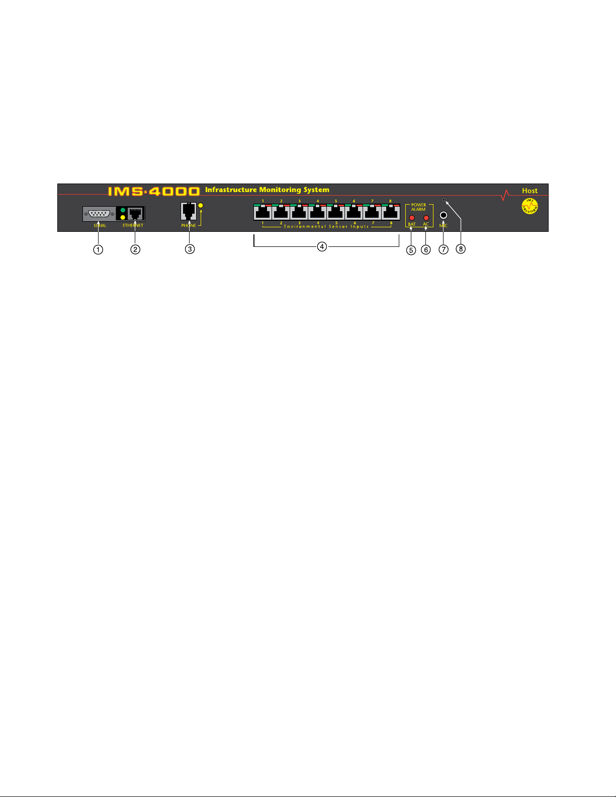
FRONT PANEL LAYOUT
The front panel contains connections for eight sensor inputs, microphone input, Ethernet port, serial port, and status LEDs.
See figure below:
Figure 1: Front Panel Layout of the IMS-4000 Host
1 Serial Port
2 Ethernet port (10/100Base-T)
3 Phone line
4 Sensor Inputs (8)
5 Battery Power Alarm LED
6 AC Power Alarm LED
7 External Microphone Input
8 Internal Microphone
SERIAL PORT
The RS-232 serial port is used to configure network settings. The port operates at 9600 baud, no parity, and 1 stop bit.
RJ-45 10/100BASE-T Ethernet Port
This jack is for connecting to your network so that the IMS-4000 Host can communicate with the IMS-4000 Nodes and
ping selected network servers and/or services. Two LEDs indicate received data (green) and transmitted data (yellow).
PHONE JACK
Connect the IMS-4000’s Phone jack to a standard 2-wire analog phone line. The unit dials using touch-tones, with loop
start only. The IMS-4000 will recognize ringer frequencies from 16 to 60 Hz and will operate with all standard analog tele-
phone systems that accept tone dialing.
Certain private telephone systems and public switching equipment may not accept the unit’s dialing or may generate an
unacceptable ring signal. In those cases, a dedicated line may be required for the unit. Consult the supplier of your tele-
phone system if you encounter problems.
CAUTION: Never install telephone wiring during a lightning storm. Never install telephone jacks in wet
locations unless the jack is specifically designed for wet locations. Never touch uninsulated telephone wires or
terminals unless the telephone line has been disconnected at the network interface. Use caution when installing
or modifying telephone lines.
SENSOR INPUTS
The sensor inputs are designed to interface with IMS-4000 series sensors (See Chapter 7). The use of RJ-45 jacks for sensor
inputs allows the use of existing structured cabling to connect remote sensors.
Since the sensor produces an analog signal, it must connect directly to the Host or Node. The path from the sensor to the
IMS unit CANNOT pass through a network Hub or Switch.

19
Chapter 1: Installation
SENSOR INPUT LEDS
Each sensor input has two LEDs (red and green) to indicate the present status of the input. The key below describes the
multiple modes of operation.
Mode 0: No sensor at input
Green: OFF
Red: OFF
Mode 1: Sensor present—No alarms
Green: ON
Red: OFF
Mode 2: Alarm detected but has not exceeded recognition time
Green: FAST BLINK
Red: FAST BLINK
Mode 3: New alarm exists and not yet acknowledged
Green: SLOW BLINK
Red: SLOW BLINK
Mode 4: Input is in normal range, but alarm is still unacknowledged
Green: ON
Red: SLOW BLINK
Mode 5: Alarm has been acknowledged, but input is still out of range
Green: SLOW BLINK
Red: ON
Mode 6: Sensor in trouble
Green: QUICK FLASH
Red: QUICK FLASH
AC POWER AND BATTERY LEDS
The AC Power and Battery alarm status is indicated by two red LEDs. Their modes of operation are described below.
Mode 1: No Alarm
LED: OFF
Mode 2: Alarm detected but has not exceeded recognition time
LED: FAST BLINK
Mode 3: New Alarm exists and not yet acknowledged
LED: SLOW BLINK
Mode 4: Alarm has been acknowledged but input is still out of range
LED: ON
MICROPHONE JACK
The Host unit comes with a built-in microphone. Directly below the built-in mic is a separate jack for connecting an
optional condenser microphone to sense audible alarms, such as smoke detectors.
When an external microphone is connected, the internal microphone is disabled.
REAR PANEL
The rear panel is where the main power switch is located. The main power cord attaches to the IEC320 connector. The unit
can be powered from 100–250VAC 50–60Hz.

IMS-4000 Manual
20
ON/OFF SWITCH
The on/off switch connects main power and battery power to the system. Note that the system will only turn on when main
power is present. When main power fails, the internal battery will automatically supply power to the unit.
Figure 2: Rear Panel of the IMS Host
INSTALLATION
This section provides information on:
• Operating environment
• Rack, wall, and tabletop installation
• Connecting sensors
Parts Required
Phillips Screwdriver • 9 pin F/F null modem cable • Dumb terminal or PC w/9 pin com port
OPERATING ENVIRONMENT
Before you install the IMS-4000 Host be sure that your operating environment meets the physical requirements of the
equipment.
Operating Temperature: 32º–122º Fahrenheit (0º–50º C)
Humidity: 5–90 %RH, non-condensing
Power: 100–250VAC 50–60 Hz outlet within 6'
Rack Requirements: Standard 19" equipment rack with supplied mounting bracket hardware.
Requires 1.0 EIA rack mount space.
Tabletop requirements: Flat area which can support an enclosure 17" wide by 10" deep by 2" high.

21
Chapter 1: Installation
RACK MOUNT INSTALLATION
The IMS-4000 Host can be rack mounted using the included rack mount brackets. Follow the steps below:
1) Attach rack-mount brackets to the sides of the Host unit with a Phillips screwdriver.
2) Attach the unit to the equipment rack using two pan-head screws per side. Tighten the screws with a Phillips
screwdriver.
3) Plug the power cord into a 100–250VAC 50/60Hz outlet.
Figure 3: Rack-mounted Host Unit
WALL MOUNT INSTALLATION
The IMS-4000 Host can be wall mounted using the optional wall mount brackets. Follow the steps below:
1) Attach the optional wall mount brackets to the sides of the IMS-4000 using the eight black #6-32 screws. A Phillips
screwdriver will be required. (Order part # IMS-4406 Universal Wall Mount Kit)
2) Attach the unit to the wall using two screws per side. Tighten the screws with a Phillips screwdriver.
3) Plug the power cord into a 100–250VAC 50/60Hz outlet.
Figure 4: Wall-mounted Host Unit
TABLETOP INSTALLATION
The IMS-4000 Host can be installed on a tabletop or shelf. Follow the steps below:
1) Attach the four self-adhesive rubber feet to the four corners on the bottom of the IMS-4000.
2) Place the unit on a tabletop or shelf and connect the power cord into a 100-250VAC outlet.
Figure 5: Tabletop-mounted Host Unit

IMS-4000 Manual
22
POWER ON SELF TEST (POST)
When the power switch is turned on, the red and green input LEDs will begin a blinking pattern to indicate that the unit is
booting up and performing internal diagnostic tests. When the LEDs stop blinking, the unit is fully booted and operational.
The boot and Power On Self Test take approximately 1 minute.
CONNECTING SENSORS
The IMS-4000 Host has eight sensor inputs. Each input can accept any sensor type. Sensors are available to monitor the fol-
lowing:
• Temperature • Smoke
• Humidity • Security
• Water detection • Motion
• AC voltage • Alarm contacts from external equipment
All IMS-4000 sensors connect to the Host using standard RJ-45 cables. This makes it easy to connect sensors directly to the
unit. Simply plug one end of the cable into the sensor and the other end into one of the sensor inputs on the Host.
Another benefit of using RJ-45 connectors is that you can easily locate sensors at distant locations within your facility by
using your existing structured cabling. For example: Suppose you have an IMS-4000 installed in room A and you want to
install a sensor in room B. If your existing cabling infrastructure has an unused cable path between room A and room B,
then you simply use an RJ-45 interconnect cable to connect the IMS-4000 to the patch panel in room A, and an RJ-45 inter-
connect cable from the wall jack in room B to the sensor.
CAUTION: The sensor produces an analog signal which must connect directly to the Host or Node. The path
from the sensor to the IMS unit CANNOT pass through a network Hub or Switch.
NETWORK CONFIGURATION
The IMS-4000 Host has a serial port on the front panel which is used to configure network settings and security options. A
dumb terminal or terminal emulation software is required to get online and set up the configuration. The port is male DTE,
so you will need to use a null modem cable. Terminal communication settings must be set to:
• 9600 baud, no parity, 8 data bits, 1 stop bit
To get online with the IMS-4000, connect your terminal to the serial port and press <RETURN>. A menu will appear which
will guide you through the setup.
Sensaphone IMS-4000 Host Unit V1.0.0.0
Enter Password ()>
{The default password for a New Unit is “ims4k”}
1. Display Enterprise status
2. Display Network and Option configuration
3. Configure Network settings
4. Configure Enterprise Name
5. Configure Web Server
6. Configure Remote Access Server
7. Enable Two-Way E-mail Responder
8. Enable Microphone Listen-In
9. Enable default Master Administrator Account (temporarily)
0. Enable data modem
A. Configure SNMP
B. Change Admin Password
C. Reset To Factory Defaults
D. Display Statistics
E. Reboot
F. Logout
Enter option->
If you select Option 1 you will see the IP address and status of the Host and all associated nodes. A sample is shown below:

23
Chapter 1: Installation
Enterprise Status
Unit Type IP Status
IMS-4000 Monitor Host 10.1.4.10 Ok
NY_Node Node 10.1.4.17 Ok
Press any key to return to main menu
Option 2 will display the network configuration for the Host as well as web server, RAS, and two-way email settings. A
sample of Option 2 is shown below:
Network and Option Configuration
Physical Address 00:D0:C9:37:40:86
IP Address 10.1.4.10
Subnet Mask 255.255.255.0
Default Gateway 10.1.4.1
DNS Server 10.1.2.111
Enterprise name U.S. Widgets Inc.
Web Server Enabled
Web Status Security Enabled
Web Programming Option Enabled
Web Programming Security Enabled
Remote Access Server Enabled
RAS IP Port Address 0.0.0.0
Two-Way E-mail Responder Enabled
Microphone Listen-in Enabled
Datamodem Enabled
SNMP RO community public
SNMP RW community private
SNMP Agent Enabled
Allow remote configuration Disabled
Press any key to return to main menu
Option 3 will allow you to set all pertinent network settings listed under Option 2.
NOTE: You can remotely reconfigure the Host network settings using the IMS-4000 ConsoleView software if the Allow
Remote Configuration option is set to Y. However, the Host must initially be configured via the serial port before any
remote configuration is possible.
Option 4 allows you to configure or reconfigure the Enterprise name.
Option 5 allows you to configure the Web server. When Web security is enabled, a Profile Username & Password must be
entered to view the web page. A sample of the Web configuration menu is shown below:
Configure Web Server
1. Enable Web Server: Y/N
2. Enable Web Status Security: Y/N
3. Enable Web Programming option: Y/N
4. Enable Web Programming Security: Y/N
5. Return to main menu
Option 6 allows you to configure the RAS (Remote Access Server). This can be used to provide remote access to your net-
work via a dial-up connection to the IMS-4000 Host. Note that there are serious security risks associated with enabling this
feature. A sample of the RAS menu is shown below:
Configure Remote Access Server
1. Enable/Disable RAS Support
2. RAS IP address
3. Return to main menu
Enter option->
Option 7 allows you to Enable or Disable the two-way email feature.
Option 8 allows you to monitor on-site sound through either the built-in or an external microphone.
Option 9 (Enable default Master Administrator Account (temporarily) should only be used in the event that no Master
Administrator accounts can be accessed (e.g. the password(s) were forgotten). Enabling this feature will temporarily load the

IMS-4000 Manual
24
default Master Administrator account (username: admin, password: ims4k). This temporary account will unload if any one
of the following occurs:
(1) Any of the Master Administrator accounts are edited,
(2) A new Master Administrator account is created, or
(3) The system reboots.
Option 0 allows you to disable all inbound modem communications. This feature is provided for users who cannot have a
device with a modem connected to their network.
Option A allows you to program the SNMP Read-Only and Read-Write community strings.
Configure SNMP
1. Read-Only community string
2. Read-Write community string
3. Enable SNMP Agent
4. Return to main menu
Enter option ->
Press ENTER to accept new setting or ESC to cancel
Enter SNMP Read-Only community string (public) >
Configure SNMP
1. Read-Only community string
2. Read-Write community string
3. Enable SNMP Agent
4. Return to main menuEnter option ->
Press ENTER to accept new setting or ESC to cancel
Enter SNMP Read=Write community string (private) >
Configure SNMP
1. Read-Only community string
2. Read-Write community string
3. Enable SNMP Agent
4. Return to main menu
Enter option ->
Option B allows you to change the Local Configuration password.
Option C allows you to reset all settings to their default values.
Option D will display statistics.
Option E will save all changes and reboot the system. A reboot is required for changes to take effect.
Option F will save all changes and logout, but the changes will not be activated until the system reboots.
LOCAL CONFIGURATION DEFINITIONS
Password: This is the password which protects access to the local configuration parameters. The default password in a new
unit is “ims4k.”
IP: This is the IP address assigned to the IMS-4000 on your network. This address is provided by you or your network
administrator. It is formatted as a standard dotted decimal number.
Mask: This is the subnet mask which distinguishes the portion of the IP address that is the network ID from the portion
that is the station ID.
Gateway: A TCP/IP network must have a gateway to communicate beyond the LAN identified by the network ID. A gate-
way is a computer or router that is connected to two different networks and can move TCP/IP data from one to the other. If
your TCP/IP network has more than one LAN or if you are connecting to the Internet, you will need to know the IP address
of the gateway that will transfer TCP/IP data in and out of your LAN. A single LAN that is not connected to other LANs
does not require a gateway setting.
DNS: The DNS server is used to translate site names into actual numeric network addresses. Enter the IP address of the
DNS server for your network.
Enable Web: Setting this to “Y” will enable the web page feature of the IMS-4000. Set this to "N" if you do not want the unit
to produce a web page.
25
Chapter 1: Installation
Enable Web Password: Setting this to “Y” will require a valid user-name and password to be entered in order to view the
web page.
Enable RAS: Setting this to “Y” will enable Remote Network Access during a dial-up connection.
RAS IP: This is the IP address assigned to the remote computer calling in to the host.
Enable 2-Way E-mail: Setting this to “Y” will enable the 2-way email feature. With this feature enabled you can send com-
mands to the IMS-4000 via e-mail and receive responses back. Set this to "N" to disable this feature.
Enterprise Name: The Enterprise name will appear at the top level of the IMS-4000 ConsoleView software whenever a user
logs in to an IMS Host. It provides identification consistency among multiple users and allows for future Enterprise features.
Enable Microphone Listen-In: Enabling this feature will allow users to listen in through the microphone on the front panel
of the unit when dialing the unit in Voice mode. Disabling this feature will prevent the microphone from being accessed
during a telephone call.
BATTERY MAINTENANCE
The IMS-4000 Host includes an internal UPS that automatically switches to battery backup in the event of an AC power
failure. The battery in the IMS-4000 Host is a 12V 2.9AH gel cell. This battery will keep the unit operating for approximately
3.5 hours when fully charged and under normal operating conditions.
Service life
Over time and with periodic use, the battery will begin to lose its capacity, resulting in less overall backup time. Under nor-
mal operating conditions, three or four years of dependable service life can be expected or between 200 and 1000 charge/
discharge cycles, depending on the average depth of discharge. Eventually, battery replacement will be required to maintain
a dependable level of service.
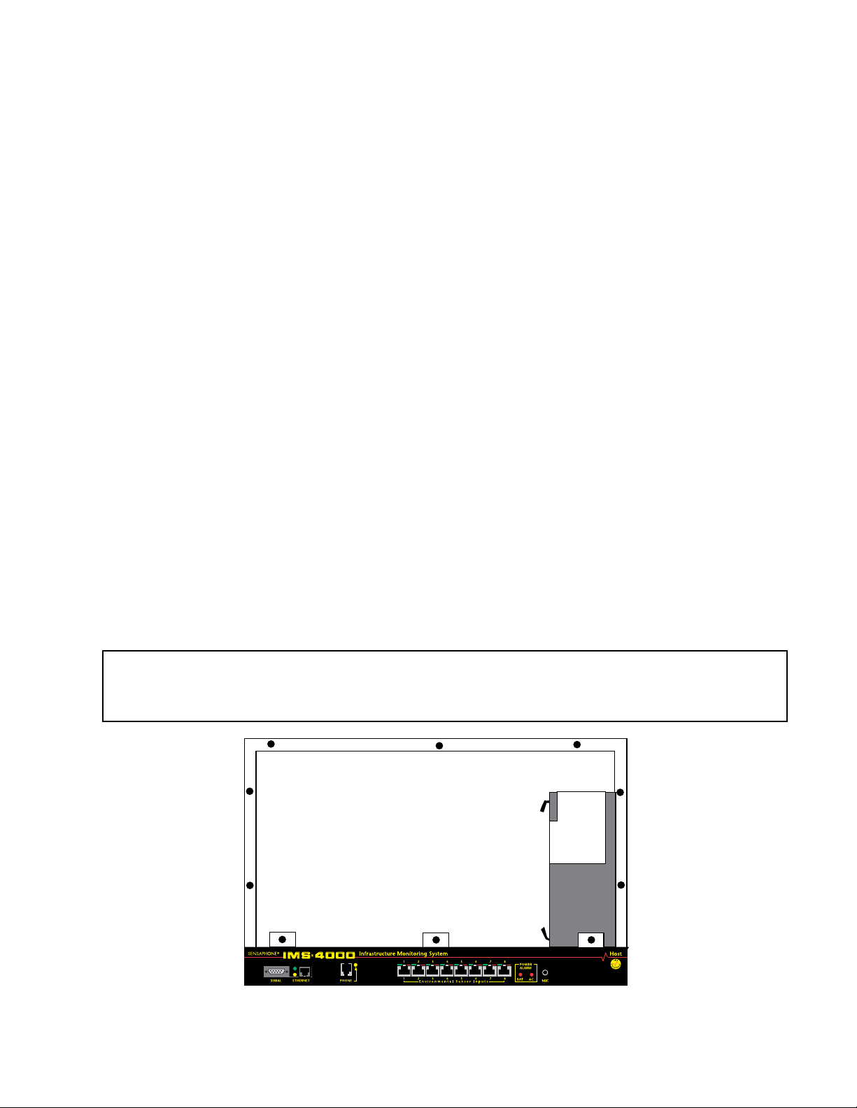
Replacing the Battery
The battery in the Host can be replaced by following the instructions listed below. Be sure to read all safety messages and
follow the instructions in order as listed. Several tools will be required to change the battery:
• small flathead screwdriver
• needle-nose pliers
• 1⁄4" nut driver
CAUTION: REPLACE BATTERY ONLY WITH A 12V 2.9AH GEL CELL BATTERY.
WARNING: DISCONNECT THE AC POWER CORD FROM THE BACK OF THE UNIT.
THERE IS A RISK OF ELECTRICAL SHOCK UNLESS YOU
DISCONNECT THE CORD.
Figure 6: Battery location
Step 1) Locate the power switch on the rear of the unit and turn the IMS-4000 off.

IMS-4000 Manual
26
Step 2) Disconnect the power cord from the back of the unit.
Step 3) Disconnect the phone line from the front of the unit.
Step 4) Remove the IMS-4000 from the rack.
Step 5) Remove all of the screws in the top cover. Carefully remove the top cover.
Step 6) Locate the battery on the right side. There will be a red wire (positive)
and a black wire (negative) connected to the battery. Using needle nose pliers,
remove the connector with the black wire from the battery first. Gently wiggle it off.
Step 7) Using needle nose pliers, remove the connector with the red wire from the battery.
Step 8) Using the nut driver, remove the four nuts which hold down the battery bracket.
Remove the bracket and battery.
Step 9) Install the new battery and replace the bracket.
Step 10) Attach the connector with the red wire to the positive terminal of the battery.
Step 11) Attach the connector with the black wire to the negative terminal of the battery.
Step 12) Replace the top IMS-4000 cover and secure with the screws.
Step 13) Re-install in rack.
Step 14) Re-attach the power cord.
Step 15) Re-connect the phone line.
Step 16) Turn the Power Switch back on.
Akkumulator austauschen

27
Chapter 1: Installation
Der Austausch des Akkumulators im Host verläuft gemäß den nachfolgenden Schritten. Lesen Sie alle Sicherheitshinweise
aufmerksam durch und folgen Sie den Anweisungen in der angegebenen Reihenfolge. Für den Austausch des Akkumulators
sind verschiedene Werkzeuge erforderlich:
• kleiner Schlitzschraubendreher
• Spitzzange
• 1⁄4”-Sechskantschlüssel
ACHTUNG: AKKUMULATOR NUR DURCH EINEN GELZELLENAKKUMULATOR (12 V, 2,9 AH) ERSETZEN.
WARNUNG: VOR AUSTAUSCH DAS NETZKABEL AUF
DER RÜCKSEITE DES GERÄTS TRENNEN.
ANDERNFALLS BESTEHT STROMSCHLAGGEFAHR.
Schritt 1) Das IMS-4000 mit dem Netzschalter auf der Rückseite des Geräts abschalten.
Schritt 2) Das Netzkabel von der Rückseite des Geräts trennen.
Schritt 3) Das Telefonkabel von der Vorderseite des Geräts trennen.
Schritt 4) Das IMS-4000 aus dem Gestell ausbauen.
Schritt 5) Alle Schrauben auf der Oberseite lösen. Die obere Abdeckung vorsichtig abnehmen.
Schritt 6) Auf der rechten Seite den Akkumulator ausfindig machen. An den Akkumulator sind
ein roter Leiter (+) und ein schwarzer Leiter (–) angeschlossen. Mit der Spitzzange
zunächst den Anschluss des schwarzen Leiters vom Akkumulator abtrennen. Dazu den
Anschluss vorsichtig mit der Spitzzange hin und her bewegen.
Schritt 7) Mit der Spitzzange den Anschluss des roten Leiters vom Akkumulator abtrennen.
Schritt 8) Mit dem Sechskantschlüssel die vier Muttern lösen, mit denen die Akkumulatorhalterung
befestigt ist. Halterung und Akkumulator herausnehmen.
Schritt 9) Neuen Akkumulator einsetzen und die Halterung wieder einbauen.
Schritt 10) Den Anschluss mit dem roten Leiter am Pluspol des Akkumulators anschließen.
Schritt 11) Den Anschluss mit dem schwarzen Leiter am Minuspol des Akkumulators anschließen.
Schritt 12) Die obere Abdeckung des IMS-4000 wieder aufsetzen und mit den Schrauben befestigen.
Schritt 13) Das IMS-4000 wieder in das Rack einbauen.
Schritt 14) Das Netzkabel anschließen.
Schritt 15) Das Telefonkabel wieder anschließen.
Schritt 16) Den Netzschalter wieder einschalten.

IMS-4000 Manual
28
IMS HOST SPECIFICATIONS
OPERATING SPECIFICATIONS
Temperature: 32-122°F
Humidity: 5–90% RH non-condensing
Power Supply: 100–250VAC 50–60Hz
Power Consumption (Typ): 25 Watts
Dimensions: 1.75"h x 9.5"d x 19"w
Backup Battery: 12V 2.9AH Sealed Gel Cell
Backup Time: 3.5 Hours
COMMUNICATION SPECIFICATIONS
Ethernet: 10/100 Base-T, 10/100Mbps
RS-232: DB9, 9600bps, DTE
Modem: 33.6Kbps
Fax: Group 3, 14.4Kbps
Voice Processor: Yes
ENVIRONMENTAL MONITORING
Internal Monitoring: AC Power (True RMS Voltage), Backup Battery Level, Sound Level (in dB)
Number of Sensor Ports: 8
Sensor Types: Temperature, Humidity, Water, Power, Infrared Motion, Smoke, Dry Contacts
Sensor Input Connector: RJ-45
Sensor Cables: CAT-5, 568B
Cable Length: 1000'
Visual Indicators: LEDs, Normal and Alarm
External Microphone: 3.5mm jack, electret conden
ser
Loading...