


SENSAPHONE®
DESKTOP MONITORING SYSTEM
Model 800
User’s Manual
Stay informed and in control of vital environmental conditions and processes with the fully-programmable
Sensaphone® Model 800.
LIT-0130

SENSAPHONE®
Model 800
User’s Manual
Version 1.3
Every effort has been made to ensure that the information in this document is complete, accurate and up-to-date. Sensaphone assumes no responsibility for the results of errors beyond its control. Sensaphone also cannot guarantee that changes in equipment made by other manufacturers, and referred to in this manual, will not affect the applicability of the information in this manual.
Copyright © 2006 by Sensaphone
First Edition, version 1.3, February, 2008
Written and produced by Sensaphone
Please address all comments on this publication to:
SENSAPHONE
901 Tryens Road Aston, PA 19014 www.sensaphone.com
Touch-Tone™ is a registered trademark of AT&T.
ii
IMPORTANT SAFETY INSTRUCTIONS
Your Model 800 has been carefully designed to give you years of safe, reliable performance. As with all electrical equipment, however, there are a few basic precautions you should take to avoid hurting yourself or damaging the unit:
•Read the installation and operating instructions in this manual carefully. Be sure to save it for future reference.
•Read and follow all warning and instruction labels on the product itself.
•To protect the Model 800 from overheating, make sure all openings on the unit are not blocked. Do not place on or near a heat source, such as a radiator or heat register.
•Do not use your Model 800 near water, or spill liquid of any kind into it.
•Be certain that your power source matches the rating listed on the AC power transformer. If you’re not sure of the type of power supply to your facility, consult your dealer or local power company.
•Do not allow anything to rest on the power cord. Do not locate this product where the cord will be abused by persons walking on it.
•Do not overload wall outlets and extension cords, as this can result in the risk of fire or electric shock.
•Never push objects of any kind into this product through ventilation holes as they may touch dangerous voltage points or short out parts that could result in a risk of fire or electric shock.
•To reduce the risk of electric shock, do not disassemble this product, but return it to Sensaphone Customer Service, or other approved repair facility, when any service or repair work is required. Opening or removing covers may expose you to dangerous voltages or other risks. Incorrect reassembly can cause electric shock when the unit is subsequently used.
•If anything happens that indicates that your Model 800 is not working properly or has been damaged, unplug it immediately and follow the procedures in Appendix F for having it serviced. Return the unit for servicing under the following conditions:
iii
Sensaphone® Model 800 User’s Manual
1.The power cord or plug is frayed or damaged.
2.Liquid has been spilled into the product or it has been exposed to water.
3.The unit has been dropped, or the cabinet is damaged.
4.The unit doesn’t function normally when you’re following the operating instructions.
•Avoid using a telephone (other than a cordless type) during an electrical storm. There may be a remote risk of electric shock from lightning.
•Do not use the telephone to report a gas leak in the vicinity of the leak.
CAUTION
To Reduce the Risk of Fire or Injury to Persons, Read and Follow these Instructions:
1.Use only the following type and size batteries: Alkaline, size C.
2.Do not dispose of the batteries in a fire. The cell may explode. Check with local codes for possible special disposal instructions.
3.Do not open or mutilate the batteries. Released electrolyte is corrosive and may cause damage to the eyes or skin. It may be toxic if swallowed.
4.Exercise care in handling batteries in order not to short the battery with conducting materials such as rings, bracelets, and keys. The battery or conductor may overheat and cause burns.
5.Do not mix old and new batteries in this product.
iv
FCC Requirements
Part 68: The Sensaphone® Model 800 complies with Part 68 of the FCC rules. On the back of the unit there is a label that contains, among other information, the FCC Registration Number and the Ringer Equivalence Number (REN) for this equipment. You must, upon request, provide this information to your local telephone company.
The REN is useful to determine the quantity of devices that you may connect to your telephone line and still have all of those devices ring when your telephone number is called. In most, but not all areas, the sum of the RENs of all devices connected to one line should not exceed five (5.0). To be certain of the number of devices that you may connect to your line, you may want to contact your local telephone company to determine the maximum REN for your calling area.
This equipment may not be used on coin service provided by the telephone company. Connection to party lines is subject to state tariffs.
Should the Model 800 cause harm to the telephone network, the telephone company may discontinue your service temporarily. If possible, they will notify you in advance. But if advance notice isn’t practical, the telephone company may temporarily discontinue service without notice and you will be notified as soon as possible. You will be informed of your right to file a complaint with the FCC. The telephone company may make changes in its facilities, equipment, operations, or procedures where such action is reasonably required in the operation of its business and is not inconsistent with the rules and regulations of the FCC that could affect the proper functioning of your
equipment. If they do, you will be notified in advance to give you an opportunity to maintain uninterrupted telephone service.
If you experience trouble with this equipment, or you need information on obtaining service or repairs, please contact:
SENSAPHONE
901 Tryens Road, Aston, PA 19014
610-558-2700 Fax: 610-558-0222
The telephone company may ask that you disconnect this equipment from the network until the problem has been corrected or until you are sure that the equipment is not malfunctioning.
v
Sensaphone® Model 800 User’s Manual
Part 15: This equipment has been tested and found to comply with the limits for a Class B digital device, pursuant to Part 15 of the FCC Rules. These limits are designed to provide
reasonable protection against harmful interference in a residential installation. This equipment generates, uses and can radiate radio frequency energy and, if not installed and used in accordance with the instructions, may cause harmful interference to radio communications. However, there is no guarantee that interference will not occur in a particular installation. If this equipment does cause harmful interference to radio or television reception, which can be determined by turning the equipment off and on, the user is encouraged to try to correct the interference by one or more of the following measures:
•Reorient or relocate the receiving antenna.
•Increase the separation between the equipment and the receiver.
•Connect the equipment into an outlet on a circuit different from that to which the receiver is connected.
•Consult the dealer or an experienced radio/television technician for help.
vi
Canadian Department of Communications Statement
Notice: The Canadian Department of Communications label identifies certified equipment. This certification means that the equipment meets certain telecommunications network protective operational and safety requirements. The Department does not guarantee the equipment will operate to the user’s satisfaction.
Before installing this equipment, users should ensure that it is permissible to be connected to the facilities of the local telecommunications company. The equipment must also be installed using an acceptable method of connection. In some cases, where the company’s inside wiring is associated with a single line, individual service may be extended by means of a certified connector assembly (telephone extension cord).
The customer should be aware that compliance with the above conditions may not prevent degradation of service in some situations.
Repairs to certified equipment should be made by an authorized
Canadian maintenance facility designated by the supplier. Any repairs or alterations made by the user to this equipment, or equipment malfunctions, may give the telecommunications company cause to request the user to disconnect the equipment.
Users should ensure for their own protection that the electrical ground connections of the power utility telephone lines and internal metallic water pipe system, if present, are connected together. This precaution may be particularly important in rural areas.
CAUTION: Users should not attempt to make such connections themselves, but should contact the appropriate electric inspection authority, or electrician, as appropriate.
The Load Number (LN) assigned to each terminal device denotes the percentage of the total load to be connected to a telephone loop which is used by the device to prevent overloading. The termination on loop may consist of any combination of devices subject only to the requirement that the total of the Load Numbers of all the devices does not exceed 100. For the Sensaphone® Model 800, the Load Number is 0.3.
vii
Sensaphone® Model 800 User’s Manual
1 YEAR LIMITED WARRANTY
PLEASE READ THIS WARRANTY CAREFULLY BEFORE USING THE PRODUCT.
THIS LIMITED WARRANTY CONTAINS SENSAPHONE’S STANDARD TERMS AND CONDITIONS. WHERE PERMITTED BY THE APPLICABLE LAW, BY KEEPING YOUR SENSAPHONE PRODUCT BEYOND THIRTY (30) DAYS AFTER THE DATE OF DELIVERY, YOU FULLY ACCEPT THE TERMS AND CONDITIONS SET FORTH IN THIS LIMITED WARRANTY.
IN ADDITION, WHERE PERMITTED BY THE APPLICABLE LAW, YOUR INSTALLATION AND/OR USE OF THE PRODUCT CONSTITUTES FULL ACCEPTANCE OF THE TERMS AND CONDITIONS OF THIS LIMITED WARRANTY (HEREINAFTER REFERRED TO AS “LIMITED WARRANTY OR WARRANTY”). IF YOU DO NOT AGREE TO THE TERMS AND CONDITIONS THIS WARRANTY, INCLUDING ANY LIMITATIONS OF WARRANTY, INDEMNIFICATION TERMS OR LIMITATION OF LIABILITY, THEN YOU SHOULD NOT USE THE PRODUCT AND SHOULD RETURN IT TO THE SELLER FOR A REFUND OF THE PURCHASE PRICE.
THE LAW MAY VARY BY JURISDICTION AS TO THE APPLICABILITY OF YOUR INSTALLATION OR USE ACTUALLY CONSTITUTING ACCEPTANCE OF THE TERMS AND CONDITIONS HEREIN AND
AS TO THE APPLICABILITY OF ANY LIMITATION OF WARRANTY, INDEMNIFICATION TERMS OR LIMITATIONS OF LIABILITY.
1.WARRANTOR: In this Warranty, Warrantor shall mean “Dealer, Distributor, and/or Manufacturer.”
2.ELEMENTS OF WARRANTY: This Product is warranted to be free from defects in materials and craftsmanship with only the limitations and exclusions set out below.
3.WARRANTY AND REMEDY: One-Year Warranty — In the event that the Product does not conform to this warranty at any time during the time of one year from original purchase, warrantor will repair the defect and return it to you at no charge.
This warranty shall terminate and be of no further effect at the time the product is: (1) damaged by extraneous cause such as fire, water, lightning, etc. or not maintained as reasonable and necessary; or (2) modified; or (3) improperly installed; or (4) misused; or (5) repaired or serviced by someone other than Warrantors’ authorized personnel or someone expressly authorized by Warrantor’s to make such service or repairs; (6) used in a manner or purpose for which the product was not intended; or (7) sold by original purchaser.
viii
LIMITED WARRANTY, LIMITATION OF DAMAGES AND DISCLAIMER OF LIABILITY FOR DAMAGES: THE WARRANTOR’S OBLIGATION UNDER THIS WARRANTY IS LIMITED TO REPAIR OR REPLACEMENT OF THE PRODUCT, AT THE WARRANTOR’S OPTION AS TO REPAIR OR REPLACEMENT. IN NO EVENT SHALL WARRANTORS BE LIABLE OR RESPONSIBLE FOR PAYMENT OF ANY INCIDENTAL, CONSEQUENTIAL, SPECIAL AND/OR PUNITIVE DAMAGES OF
ANY KIND, INCLUDING BUT NOT LIMITED TO ANY LABOR COSTS, PRODUCT COSTS, LOST REVENUE, BUSINESS INTERRUPTION LOSSES, LOST PROFITS, LOSS OF BUSINESS, LOSS OF DATA OR INFORMATION, OR FINANCIAL LOSS, FOR CLAIMS OF ANY
NATURE, INCLUDING BUT NOT LIMITED TO CLAIMS IN CONTRACT, BREACH OF WARRANTY OR TORT, AND WHETHER OR NOT CAUSED BY WARRANTORS’ NEGLIGENCE. IN THE EVENT THAT IT IS DETERMINED IN ANY ADJUDICATION THAT THE LIMITED WARRANTIES OF REPAIR OR REPLACEMENT ARE INAPPLICABLE, THEN THE PURCHASER’S SOLE REMEDY SHALL BE PAYMENT TO
THE PURCHASER OF THE ORIGINAL COST OF THE PRODUCT, AND IN NO EVENT SHALL WARRANTORS BE LIABLE OR RESPONSIBLE FOR PAYMENT OF ANY INCIDENTAL, CONSEQUENTIAL, SPECIAL AND/OR PUNITIVE DAMAGES OF ANY KIND, INCLUDING BUT NOT LIMITED TO ANY LOST REVENUE, BUSINESS INTERRUPTION LOSSES, LOST PROFITS, LOSS OF BUSINESS, LOSS OF DATA OR INFORMATION, OR FINANCIAL LOSS, FOR CLAIMS OF ANY NATURE, INCLUDING BUT NOT LIMITED TO CLAIMS IN CONTRACT, BREACH OF WARRANTY OR TORT, AND WHETHER OR NOT CAUSED BY WARRANTORS’ NEGLIGENCE.
WITHOUT WAIVING ANY PROVISION IN THIS LIMITED WARRANTY, IF A CIRCUMSTANCE ARISES WHERE WARRANTORS ARE FOUND TO BE LIABLE FOR ANY LOSS OR DAMAGE ARISING OUT OF MISTAKES, NEGLIGENCE, OMISSIONS, INTERRUPTIONS, DELAYS,
ERRORS OR DEFECTS IN WARRANTORS’ PRODUCTS OR SERVICES, SUCH LIABILITY SHALL NOT EXCEED THE TOTAL AMOUNT PAID BY THE CUSTOMER FOR WARRANTORS’ PRODUCT AND SERVICES
OR $250.00, WHICHEVER IS GREATER. YOU HEREBY RELEASE WARRANTORS FROM ANY AND ALL OBLIGATIONS, LIABILITIES AND CLAIMS IN EXCESS OF THIS LIMITATION.
INDEMNIFICATION AND COVENANT NOT TO SUE: YOU WILL INDEMNIFY, DEFEND AND HOLD HARMLESS WARRANTORS, THEIR OWNERS, DIRECTORS, OFFICERS, EMPLOYEES, AGENTS, SUPPLIERS OR AFFILIATED COMPANIES, AGAINST ANY AND ALL CLAIMS, DEMANDS OR ACTIONS BASED UPON ANY LOSSES, LIABILITIES, DAMAGES OR COSTS, INCLUDING BUT NOT LIMITED TO DAMAGES THAT ARE DIRECT OR INDIRECT, INCIDENTAL, SPECIAL OR CONSEQUENTIAL, AND INCLUDING ATTORNEYS FEES AND LEGAL COSTS, THAT MAY RESULT FROM THE INSTALLATION, OPERATION, USE OF, OR INABILITY TO USE
WARRANTORS’ PRODUCTS AND SERVICES, OR FROM THE FAILURE
ix
Sensaphone® Model 800 User’s Manual
OF THE WARRANTORS’ SYSTEM TO REPORT A GIVEN EVENT OR CONDITION, WHETHER OR NOT CAUSED BY WARRANTORS’ NEGLIGENCE.
YOU AGREE TO RELEASE, WAIVE, DISCHARGE AND COVENANT NOT TO SUE WARRANTORS, THEIR OWNERS, DIRECTORS, OFFICERS, EMPLOYEES, AGENTS, SUPPLIERS OR AFFILIATED COMPANIES, FOR ANY AND ALL LIABILITIES POTENTIALLY ARISING FROM ANY CLAIM, DEMAND OR ACTION BASED UPON ANY LOSSES, LIABILITIES, DAMAGES OR COSTS, INCLUDING BUT NOT LIMITED TO DAMAGES THAT ARE DIRECT OR INDIRECT, INCIDENTAL, SPECIAL OR CONSEQUENTIAL, AND INCLUDING ATTORNEYS FEES AND LEGAL COSTS, THAT MAY RESULT FROM THE INSTALLATION, OPERATION, USE OF, OR INABILITY TO USE WARRANTORS’ PRODUCTS AND SERVICES, OR FROM THE FAILURE OF THE WARRANTORS’ SYSTEM TO REPORT A GIVEN EVENT OR CONDITION, WHETHER OR NOT CAUSED BY WARRANTORS’ NEGLIGENCE, EXCEPT AS NECESSARY TO ENFORCE THE EXPRESS TERMS OF THIS LIMITED WARRANTY.
EXCLUSIVE WARRANTY: THE LIMITED WARRANTY OR WARRANTIES DESCRIBED HEREIN CONSTITUTE THE SOLE WARRANTY OR WARRANTIES TO THE PURCHASER. ALL IMPLIED WARRANTIES ARE EXPRESSLY DISCLAIMED, INCLUDING: THE WARRANTY
OF MERCHANTABILITY AND THE WARRANTY OF FITNESS FOR A PARTICULAR USE AND THE WARRANTY OF FITNESS FOR A PARTICULAR PURPOSE AND THE WARRANTY OF NON-
INFRINGEMENT AND/OR ANY WARRANTY ARISING FROM A COURSE OF DEALING, USAGE, OR TRADE PRACTICE.
It must be clear that the Warrantors are not insuring your premises or business or guaranteeing that there will not be damage to your person or property or business if you use this Product. You should maintain insurance coverage sufficient to provide compensation for any loss, damage, or expense that may arise in connection with the use of products or services, even if caused by Warrantors’ negligence. The warrantors assume no liability for installation of the Product and/or interruptions of the service due to strikes, riots, floods, fire, and/or any cause beyond Seller’s control, further subject to the limitations expressed in any License Agreement or other Agreement provided by Warrantors to purchaser.
The agreement between the Warrantors and the Purchaser, including but not limited to the terms and conditions herein shall not be governed by the Convention for the International Sale of Goods. Where applicable, the Uniform Commercial Code as adopted by the State of Delaware shall apply.
4. PROCEDURE FOR OBTAINING PERFORMANCE OF WARRANTY: In the event that the Product does not conform to this warranty, the Product should be shipped or delivered freight prepaid to a Warrantor with evidence of original purchase.
x
5.LEGAL REMEDIES AND DISCLAIMER: Some jurisdictions may not allow, or may place limits upon, the exclusion and/or limitation of implied warranties, incidental damages and/or consequential damages for some types of goods or products sold to consumers and/or the use of indemnification terms. Thus, the exclusions, indemnification terms and limitations set out above may not apply, or may be limited in their application, to you. If the implied warranties can not be excluded, and the applicable law permits limiting the duration of implied warranties, then the implied warranties herein are to be limited to the same duration as the applicable written warranty or warranties herein. The warranty or warranties herein may give you specific legal rights that will depend upon the applicable law. You may also have other legal rights depending upon the law in your jurisdiction.
6.CHOICE OF FORUM AND CHOICE OF LAW: In the event that a dispute arises out of or in connection with this Limited Warranty, then any claims or suits of any kind concerning such disputes shall only and exclusively be brought in either the Court of Common Pleas of Delaware County, Pennsylvania or the United States District Court for the Eastern District of Pennsylvania.
Regardless of the place of contracting or performance, this Limited Warranty and all questions relating to its validity, interpretation, performance and enforcement shall be governed by and construed in accordance with the laws of the State of Delaware, without regard to the principles of conflicts of law.
Effective date 05/01/2004 SENSAPHONE
901 Tryens Road
Aston, PA 19014
Phone: 610.558.2700 Fax: 610.558.0222 www.sensaphone.com
xi
xii
TABLE OF CONTENTS
IMPORTANT SAFETY INSTRUCTIONS . . .iii.
FCC Requirements . . . . . . . . . . . . . . . . . . . v. . . .
Canadian Department of Communications Statement . vii
1 YEAR LIMITED WARRANTY . . . . . . . . . . . . viii. . . . .
Chapter 1: Introduction . . . . . . . . . . 18. . . .
Layout . . . . . . . . . |
. . . . . . |
. . |
20 |
|
1. |
Programming Keypad |
. . . . . . |
. . . . 20 |
|
2. |
Power Jack . . . . . . |
. . . . . . |
. . . . 20 |
|
3. |
Phone Extension Jack . . |
. . . . . |
. . . . .20 |
|
4. |
Phone Line Jack . . . . |
. . . . . . |
. . . . 20 |
|
5. |
Speaker . . . . . . . . |
. . . . . |
. . . . |
20 |
6. |
Built in Microphone . . . |
. . . . . |
. . . . .20 |
|
7. |
System on LED . . . . . |
. . . . . |
. . . . .20 |
|
8. |
Phone-in-use LED . . . . |
. . . . . |
. . . . .20 |
|
9. |
Alarm LED . . . . . . . |
. . . . . |
. . . . .20 |
|
10. Battery OK LED . . . . |
. . . . . |
. . . . |
.20 |
|
11.Battery Compartment . . . . . . . . . . . .20
12.Input/Output Wiring Door . . . . . . . . . . 20 LED INDICATORS . . . . . . . . . . . . . . 20
Technical Support . . . . . . . . . . . . . . .21
Chapter 2: Installation . . . . . . . . . . . 22. . . .
2.1Operating Environment . . . . . . . . . . . 22
2.2Mounting . . . . . . . . . . . . . . . . .22
2.3Power Surge Protection . . . . . . . . . . .23
2.4Power Supply and Battery Backup . . . . . . 23
2.5Starting the Model 800 . . . . . . . . . . . 24
2.6Run Mode and Standby Mode . . . . . . . . 24
2.7Telephone Line . . . . . . . . . . . . . .25
xiii
2.8The Microphone . . . . . . . . . . . . . .26
2.9Alert Zones . . . . . . . . . . . . . . . .27
2.11Installing the Sensor . . . . . . . . . . . 28
2.11Multiple Sensors . . . . . . . . . . . . .29
2.12Outdoor Wiring . . . . . . . . . . . . . .30
2.13Disconnecting the Model 800 for Storage or
Seasonal Use. . . . . . . . . . . . . . . . . 31
Chapter 3: Quick Start . . . . . . . . . . . 32. . . . .
3.1The Local Keypad . . . . . . . . . . . . .32
3.2Preparation for Programming . . . . . . . . .32
3.3Quick-Start Programming Steps . . . . . . . 33
3.4Summary of the Alarm Dial-Out Process . . . . 38
Chapter 4: Communications
Programming . . . . . . . . . . . . . . . .40. . . . .
4.1Voice Messages . . . . . . . . . . . . . .40
4.2The Unit ID Number . . . . . . . . . . . . 43
4.2.1Programming the ID Number . . . . . . . . . 44
4.2.2Interrogating the ID Number . . . . . . . . . 44
4.3Dial-out Telephone Numbers . . . . . . . . .45
4.3.1Programming Dial-out Telephone Numbers . . . 45
4.3.2Interrogating a Dial-out Telephone Number . . . 46
4.3.3Erasing a Telephone Number . . . . . . . . . 47
4.4Dial-Out Test Mode . . . . . . . . . . . . . . 47
4.4.1To test a dialout phone number: . . . . . . . . 47
4.4.2Manually Dial a Telephone Number . . . . . . 48
4.5Tone or Pulse Dialing . . . . . . . . . . . 49
4.6Special Dialing . . . . . . . . . . . . . . 49
4.6.1Special Dialing Keys . . . . . . . . . . . . 49
4.6.2 Incorporating a Pause . . . . . . . . . . . 51
4.6.3Incorporating a Pound (#) or Star (*) . . . . . . 53
4.6.4Special Dialing to a Beeper or Pager . . . . . . 54
4.7Rings Until Answer . . . . . . . . . . . . .55
4.7.1Programming Rings Until Answer . . . . . . . 55
xiv
4.7.2Interrogating Rings Until Answer . . . . . . . . 55
4.8TAD (Telephone Answering Device) . . . . . 56
4.8.1TAD Enable/Disable . . . . . . . . . . . . 56
4.8.2Using the TAD Feature . . . . . . . . . . . 56
4.8.3No TAD In Use . . . . . . . . . . . . . . 57
4.9Listen-in Time . . . . . . . . . . . . . . 58
4.9.1Programming the Listen-in Time . . . . . . . . 58
4.9.2Interrogating the Listen-in Time . . . . . . . . 59
4.10Call Delay . . . . . . . . . . . . . . . .59
4.10.1Programming the Call Delay . . . . . . . . . 59
4.10.2Interrogating Call Delay . . . . . . . . . . . 60
4.11Local Voice Mute . . . . . . . . . . . . .60
4.11.1Enable/Disable Local Voice Mute . . . . . . . 61
4.12Voice Repetitions . . . . . . . . . . . . .61
4.12.1Programming Voice Repetitions . . . . . . . 61
4.12.2Interrogating Voice Repetitions . . . . . . . . 62
4.13Intercall Time . . . . . . . . . . . . . . 62
4.13.1Programming Intercall Time . . . . . . . . . 63
4.13.2Interrogating Intercall Time . . . . . . . . . 64
4.14Maximum Number of Calls (Max Calls) . . . . 64
4.14.1Programming Max Calls . . . . . . . . . . 64
4.14.2Interrogating Max Calls . . . . . . . . . . . 65
4.15The Clock . . . . . . . . . . . . . . . .65
4.15.1Setting the Clock . . . . . . . . . . . . . 66
4.15.2Interrogating for the Current Time . . . . . . . 66
4.16The Security Code . . . . . . . . . . . . 67
4.16.1Locking the Keypad . . . . . . . . . . . . 67
4.16.2Unlocking the Keypad . . . . . . . . . . . 68
Chapter 5: Alarm Programming . . . . . .69. .
5.1Zone Configuration . . . . . . . . . . . . 69
5.1.1Programming Zone Configuration . . . . . . . 70
5.1.2Interrogating Zone Configuration . . . . . . . 71
5.2Enable/Disable Zones . . . . . . . . . . . 71
5.2.1Changing Enabled/Disabled Zone Status . . . . 71
5.2.2 Verifying Enabled/Disabled Zone Status . . . . 71
xv
5.3Zone Recognition Time . . . . . . . . . . .72
5.3.1Programming Zone Recognition Time . . . . . 72
5.3.2Interrogating Zone Recognition Time . . . . . . 74
5.4Establishing High and Low Temperature Limits .74
5.4.1Programming Temperature Limits for a Selected
Zone . . . . . . . . . . . . . . . . . 74
5.4.2Disabling Alarm Response to High or Low Temperature . . . . . . . . . . . . . . . 76
5.4.3Interrogating High and Low Temperature Limits . . 76
5.5 Temperature Scale . . . . . . . . . . . . 77
5.6Temperature Calibration . . . . . . . . . . 77
5.6.1Programming Temperature Calibration . . . . . 77
5.6.2Interrogating Temperature Calibration . . . . . 79
5.7Obtaining Current Temperature . . . . . . . .79
5.8AC Power Monitoring Enable/Disable . . . . . 80
5.8.1Enabling/Disabling the AC Power Alarm . . . . . 80
5.9AC Power Failure Recognition Time . . . . . . . . . . .80
5.9.1 Programming Power Failure Recognition . . . . .
Time . . . . . . . . . . . . . . . . . 81
5.9.2Interrogating Power Failure Recognition Time . . 82
5.10Sound Alarm Monitoring . . . . . . . . . .82
5.10.1Programming Sound Alarm Sensitivity . . . . . 82
5.10.2Interrogating Sound Sensitivity . . . . . . . . 83
5.10.3Programming High Sound Alarm Recognition
Time . . . . . . . . . . . . . . . . . 83
5.10.4Interrogating High Sound Alarm Recognition Time . 84
5.11High Sound Alarm Enable/Disable . . . . . .84
5.11.1Changing Enabled/Disabled High Sound Alarm . 85
5.12Exit Delay . . . . . . . . . . . . . . . 85
5.13Designating A Zone As Unused . . . . . . .86
Chapter 6: Acknowledgment, Status Report
& Remote Access . . . . . . . . . . . . . . .87. . . . .
6.1Alarm Acknowledgment . . . . . . . . . . .87
6.1.1Local Acknowledgment . . . . . . . . . . . 87
xvi
6.1.2Touch-Tone™ Acknowledgment . . . . . . . . 87
6.1.3Callback Acknowledgment . . . . . . . . . . 88
6.2Status Report . . . . . . . . . . . . . . 89
6.2.1Example: Status Report, No Alarms . . . . . . 90
6.2.2Example: Status Report, Existing Alarms . . . . 91
6.2.3Example: Status Report, Disabled Zones . . . . 92
6.2.4Battery Condition . . . . . . . . . . . . . . 93
6.2.5Remote Access by Touch-Tone™ Telephone . . 93
Chapter 7: Operation . . . . . . . . . . . .97. . .
7.1 |
Alarm Detection, Dial-out and |
|
|
Acknowledgment . . . . . . . . . . . . . . 97 |
|||
7.2 |
Example: A Dial-out Telephone Call . . . |
. |
. 102 |
Chapter 8: Controlling the Output . . . |
. |
. 103. . . |
|
8.1Output Modes . . . . . . . . . . . . . . 103
8.1.1To program the Output Mode: . . . . . . 104
8.1.2To play back the programmed Output Mode: .105
8.2Switching The Output Using The Keypad . . . .106
8.3Typical Applications . . . . . . . . . . . .106
8.3.1 Single Thermostat Control . . . . . . . . . 107
8.3.2Dual Thermostat Control . . . . . . . . . . 109
8.3.3Controlling Lights Or Other Devices . . . . . . 111
Appendix A: Weekly Testing Procedure . |
. |
. . |
. |
. 113. . . . |
Appendix B: Troubleshooting . . . . . . |
. |
. . . |
. |
.115. . . . |
Appendix C: 800 QUICK REFERENCE . . |
. . . . . .125. . . . |
|||
Appendix D: Accessories . . . . . . . . . |
. . . . . 128. . . . . |
|||
Appendix E: Specifications . . . . . . . . . . . . . .129. . . . |
||||
Appendix F: Returning the Unit for Repair |
. |
. . |
. |
. 131. . . |
Appendix F: Test Log . . . . . . . . . . . |
. |
. . |
. |
. 132. . . . . |
xvii
Chapter 1: Introduction
The Sensaphone® Model 800 is a fully-programmable, environmental monitoring system that offers extensive on-site and remote monitoring capability to small businesses, private homes, farms, greenhouses, computer rooms, and remote facilities. Designed for desktop or wall mounting, the Model 800 is simple to install, program and operate; no changes to standard electrical or telephone service are required. When connected to a telephone line, it will respond to an alarm by dialing up to four separate telephone numbers. When the call is answered, an “Alert Condition” message is delivered in user recordable voice.
The Model 800 features built-in sensors to monitor a variety of conditions:
•High sound level
•AC electric power failure
•Battery backup
•Temperature*
*Note: While technically not a “built-in” sensor, temperature is factory installed on zone 1.
The 800 is equipped with 8 alert zones. Additional sensors* can be added to extend monitoring capabilities to include:
•Intrusion or unauthorized entry
•Water leaks and seepage
•Temperature
•Humidity
•Equipment operation
•Many other conditions that may require unique monitoring solutions
* Refer to Appendix D for information on additional sensors (available separately from Sensaphone) best suited to your application.
The status of each monitored condition is readily obtained at the unit’s installation site, or remotely by telephone. At the close of every Status Report, time is provided for listening to on-site sounds.
To ensure reliable operation, the Model 800 features power backup capability; in the event of AC power failure, six C-cell
18
Chapter 1: Introduction
alkaline batteries (not included) will continue to power the unit for approximately 24 hours.
Feature Summary
The Sensaphone 800 includes the following features:
•Eight zones configurable as temperature or dry contact
•Each zone can be individually enabled or disabled
•Fully automatic input configuration
•Temperature sensor included on zone #1
•Calibration for each zone
•Power monitor
•High sound-level monitor
•User-recordable voice messages
•Dial out to eight telephone numbers
•Alarm dial out via voice and numeric pager
•Microphone for onsite listen-in
•Built-in line seizure
•Relay output (manual or automatic control)
•Four status LEDs
•Surge protection on all zones, telephone line, and power supply
•24 hour battery backup (batteries not included)
•Wall or desktop installation
About This Manual
This manual comprises the instructions and commands for installing and operating the Model 800. The Quick Start chapter is included to speed understanding of programming and operation.
Communication and Alarm Programming chapters demonstrate step-by-step methods for utilizing the full range of available features. The Troubleshooting chapter provides assistance in the event that problems are encountered.
19

Sensaphone® Model 800 User’s Manual
Layout |
|
|
|
|
|
|
2 |
3 |
4 |
12 |
7 |
|
|
|
|
|
|
|
|
|
|
|
|
|
8 |
1. |
Programming Keypad |
|
|
|
|
9 |
2. |
Power Jack |
5 |
|
|
|
10 |
3. |
Phone Extension Jack |
|
|
|
|
4. |
Phone Line Jack |
|
|
|
|
|
|
||
|
|
|
|
1 |
5. |
Speaker |
|
|
|
|
|
6. |
Built in Microphone |
6 |
|
|
|
|
7. |
System on LED |
11 |
|
|
|
|
8. |
Phone-in-use LED |
|
|
|
|
9. |
Alarm LED |
|
|
|
|
|
|
||
10. Battery OK LED
11. Battery Compartment
12. Input/Output Wiring
Door
LED INDICATORS
The LEDs provide on-site alarm and status information. Listed below are descriptions of how the LEDs work.
System On
LED Off: Unit is off
LED On: Unit is in Run mode
LED Blinking: Unit is in Standby mode
Phone-In-Use
LED On: The unit or some other device is communicating on the phone line
LED Off: Phone line is not in use
LED Blinking: No telephone service detected
20
Chapter 1: Introduction
Alarm
LED Off: No alarms exist
LED Blinking: Unacknowledged alarm exists LED On: Acknowledged alarm exists
Battery OK
LED On: Battery condition good LED Blinking: Battery condition low
LED Off: No battery/critically low battery condition
Technical Support
If any questions arise upon installation or operation of the Model
800, please contact the Sensaphone Technical Service Department at the number shown below, and have the following information:
•Date of Purchase _______________
•Serial number of your Model 800 _________________
Technical Support is available from 8:00am to 5:00pm EST.
You may also email us at support@sensaphone.com.
Sensaphone
901 Tryens Road Aston, PA 19014 610-558-2700 Fax: 610-558-0222 www.sensaphone.com
21

Chapter 2: Installation
Correctly installing the Model 800 will ensure proper functioning of the unit. Please read the entire chapter before starting the installation process.
Within the packaging will be a Warranty Registration Card. Please take the time to fill this out and mail. The One Year Limited Warranty is explained in the front of this manual.
2..1 Operating Environment
The Model 800 should be installed and operated in a clean, dry area that provides space for wiring sensors to the screw
terminals, near an AC power source and telephone line. Operating temperature ranges from 32° Fahrenheit (0° Celsius) to +122° Fahrenheit (+50° Celsius).
NOTE
The Model 800 is a sensitive electronic device. Do not install the Model 800 near strong electrostatic, electromagnetic or radioactive fields. Do not expose to humid environments, fumes, or corrosive vapors.
2..2 Mounting
Flat Mount: Place the Model 800 on top of a desk or other horizontal surface. Wall Mount: Mount on a wall with two flathead screws using the keyholes on the back panel of the unit.
Place the flathead screws or bolts 4” apart at the desired height from the floor. Hook the unit over the screws and toward the floor. Refer to Figure 2-1.
2
4
Figure 2-1.. Wall Mount
22

Chapter 2: Installation
2..3 Power Surge Protection
The Model 800 can be damaged by power surges and lightning through the telephone line and the 120 VAC power supply.
Although the Model 800 has built-in surge protection, we recommend that additional protection be obtained for the unit and for any electronic equipment that is attached to your power supply and telephone lines. Power surge protection is especially important if you live in a lightning-prone area. The ISOTEL Surge Protector Model IB-4 is available through Sensaphone. See Appendix D.
2..4 Power Supply and Battery Backup
The Model 800 is provided with a DC power transformer that will plug into any standard 120 VAC outlet and a battery
backup (batteries not included) that enables the unit to continue functioning if AC power is removed (due to electric power disruption or failure). The Model 800 uses six, C-cell alkaline batteries. Do not use rechargeable batteries. Connect the DC power transformer into the jack on the back of the unit and plug the adapator into a 120VAC outlet
NOTE
Be sure that the DC transformer is plugged into an outlet before installing batteries.
To install the batteries, remove the battery compartment door located on the front of the unit below the keypad. Press down and slide the door away from the unit, align batteries according to the diagram shown in Figure 2-2, and replace the hatch.

3IZE
#

3IZE
#
3IZE
#
|
3IZE |
|
3IZE |
|
3IZE |
|
|
# |
# |
# |
|||||
|
|
|
|
Figure 2-2.. Battery Installation
23

Sensaphone® Model 800 User’s Manual
2..5 Starting the Model 800
When the DC power transformer is first plugged into the electrical outlet, the Model 800 automatically starts in RUN mode. The System On light will begin to glow. The unit will respond with,“Hello, this is Sensaphone 800.”
2..6 Run Mode and Standby Mode
Pressing the RUN/STANDBY key on the Model 800 keypad will alternately activate or deactivate the unit. If the unit is activated and in RUN mode, the system on light glows steadily. In STANDBY mode, the system on light goes out, but will blink every few seconds to indicate that power is still supplied to the unit.
In RUN mode, the Model 800 is able to receive incoming calls and to dial out automatically in the event of an alarm on one of the monitored conditions. To enter STANDBY mode, press RUN/ STANDBY.
As soon as the Model 800 enters STANDBY mode, it responds with “Goodbye.” The system on light immediately goes out and then resumes with a blink every few seconds. While in
STANDBY mode, all functions are disabled, but programmed memory is preserved. Upon exiting STANDBY mode, any currently existing alarms will be announced.
NOTE
STANDBY mode is not equivalent to “power off”—an electrical source, such as the 120 VAC, or the battery backup, continues to provide full power to the unit. If the unit is placed in STANDBY mode, unplugged from the 120 VAC outlet, and placed
in storage, the batteries will continue to power the Model 800, discharging until they fail. Consequently, batteries should always be removed from the unit following disconnection from any 120 VAC outlet, prior to storage.
Press the RUN/STANDBY key again to return to RUN mode.
RUN
STANDBY
Figure 2-3.. The RUN/STANDBY Key
24
Chapter 2: Installation
2..7 Telephone Line
The Model 800 will operate with all standard analog telephone lines that accept pulse or tone dialing. The Model 800 cannot be used on an extension line to dial its own telephone number. Also, it may not be installed on a party line, pay telephone line, or digital telephone system.
Certain private telephone systems and public switching equipment may not accept the Model 800 dialing or may generate an unacceptable ring signal. In those cases, a dedicated line may be required. Consult the supplier of your telephone system if you encounter problems.
If you do not have a modular telephone extension at the Model
800’s location, you must contact your local telephone company to have one installed (there is a charge for this service). If you have four-pin jacks, adapters are available to convert them to the modular plugs. Contact your local telephone company or electronics parts store.
CAUTION
Never install telephone wiring during a lightning storm. Never install telephone jacks in wet locations unless the jack is specifically designed for wet locations. Never touch uninsulated telephone wires or terminals unless the telephone line has been disconnected at the network interface. Use caution when installing or modifying telephone lines.
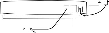
To install the telephone line, plug one end of the modular cord into the “line” jack on the back of the model 800 (as shown) and plug the other end into any standard RJ11 phone outlet.
Refer to Figure 2-4.
Line Ext Pwr |
AC Power |
Transformer |
|
|
(plug into |
|
120 VAC outlet) |
RJ11 Outlet |
|
|
|
|
Female Telephone Jack |
|||
|
|
|
|
|||||
(for modular |
|
|
|
|
|
|
|
|
|
|
|
||||||
telephone jack) |
|
|
|
(connect telephone here) |
||||
|
|
|
|
|
|
Modular Plug |
||
|
|
|
|
|
|
|
|
|
|
|
|
|
|
|
(plug into RJ1 jack) |
||
Figure 2-4.. Installing the Telephone Line
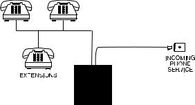
On the back of the Model 800 is an extra female telephone jack labeled “EXT”. This is provided so that a telephone or other answering device may be used on the same line as the unit.
25
Sensaphone® Model 800 User’s Manual
(It is not necessary to hook up a telephone for the Model 800 to operate.) This extension jack features Line Seizure which means that it will disconnect the extension jack when the Model 800 needs to make a telephone call. To ensure that the unit has priority over any other device on the line, you must connect all extensions to this jack. (see figure)
On the unit there are two RJ11C phone jacks:
•The RJ11C jack labeled “LINE”is to be connected to the incoming line of your phone service, ahead of all other phones or telephone extensions.
•The RJ11C telephone jack labeled “EXT” is to be connected to all extensions.
2..8 The Microphone
The Model 800 is provided with a built-in microphone which is used to monitor high sound levels produced near the installation site. The sensitivity of the microphone is configurable and
will detect a continuous as well as a pulsating alarm. Note that beeping alarms that have a half second or more of silence between beeps will not be detected.
Other programming options that apply to the microphone include setting the length of time before a high sound causes an alarm.
If this sound level exists for 8 consecutive seconds (default) or for the programmed length of time, the Model 800 will dial out with an alarm message.
26

Chapter 2: Installation
NOTE
The proximity of the audible alarm to the microphone is extremely important.
Normally, the Model 800 and the audible alarm must be in the same room. The maximum distance can vary considerably
depending on the alarm, the acoustics, and the size of the room.
During an alarm dial-out, the microphone allows four-second intervals to listen-in to sounds at the Model 800’s location.
When calling for a Status Report, the microphone permits listening to on-site sounds for a programmed time interval.
2..9 Alert Zones
Open the input/output wiring door located above the keypad. The Model 800 can monitor up to 8 zones (represented by the numbered terminal screws shown in Figure 2-5, below).
|
# |
|
# |
|
# |
|
# |
|
# |
|
# |
|
# |
|
# |
|
|
|
|
|
|
|
|
|
|
|
|
|
|
|
|
:/.%3
Figure 2-5.. Alert Zones
Zones are configured as either dry contact or temperature. A zone configured as dry contact can be used with any normally open
(N.O.) or normally closed (N.C.) device. “Open” refers to an opened circuit path; if conditions cause the circuit to close, an alert condition occurs. “Closed” refers to a continuous circuit path; if a closed circuit is opened, an alert condition occurs. The
Model 800 determines the way zones are configured by the type of sensor connected to each alert zone (refer to Chapter 5.)
A zone configured as “temperature” is designed to evaluate a range of settings. The Model 800 will read the temperature at the sensor’s location and compare that value to programmed high and low temperature limits. Temperature zones must be used with Sensaphone’s 2.8K Remote Temperature Sensor or weatherproof sensor.
NOTE
Before wiring, it is advisable to disable the zones to prevent accidentally tripping an alarm. See Chapter 5.
27

Sensaphone® Model 800 User’s Manual
Important Note regarding Ultra-Low temperature freezers:
If you are connecting the Sensaphone to an ultralow temperature freezer (-80° C) and the freezer is equipped with alarm terminals/ contacts you can connect these directly to one of the zones on your Sensaphone (refer to your freezer owner’s manual for proper connection.
2..10 Installing the Sensor
After you have selected the sensor, loosen the screw of the alert zone and its corresponding common (c). Two wire leads are used to connect any monitoring sensor. Fasten one lead to the numbered screw and the other lead to C. Tighten both screws. If the zone was not disabled, the Model 800 may recite its “Alarm Exists” message as you connect the sensor. If it does, just press ALARM CANCEL to stop it. Re-enable the zone after wiring. Refer to Figures 2-6 and 2-7 for connecting a sensor to an alert zone.
|
# |
|
# |
|
# |
|
# |
|
# |
|
# |
|
# |
|
# |
|
|
|
|
|
|
|
|
|
|
|
|
|
|
|
|
:/.%3
3ENSOR WIRED TOW !LERTE)NPUT
Figure 2-6.. Sensor Connected to an Alert Zone
Any sensor can be attached to the Model 800 using 18-26-gauge wire (#22 recommended). The sensor can be several hundred feet from the unit, as long as the total resistance of the circuit is not greater than 50 ohms. Use wire appropriate for the application.
28
 Loading...