

Sennheiser SL Connection Manual
SL Ceiling Mic
Connection Guide
Sennheiser electronic GmbH & Co. KG
Am Labor 1, 30900 Wedemark, Germany, www.sennheiser.com
TI 1095 v1.0
SL Ceiling Mic Connection Guide | 1/5
SL Ceiling Mic Connection Guide
SL Ceiling Mic Connection Guide
This document provides information on how to connect the SL Ceiling Mic to the Sennheiser TeamConnect system and to 3rd party media control systems.
For further information on the SL Ceiling Mic please refer to the instruction manual,
which is available for download on the product page of the SL Ceiling Mic or in the Sennheiser download area at www.sennheiser.com/download.
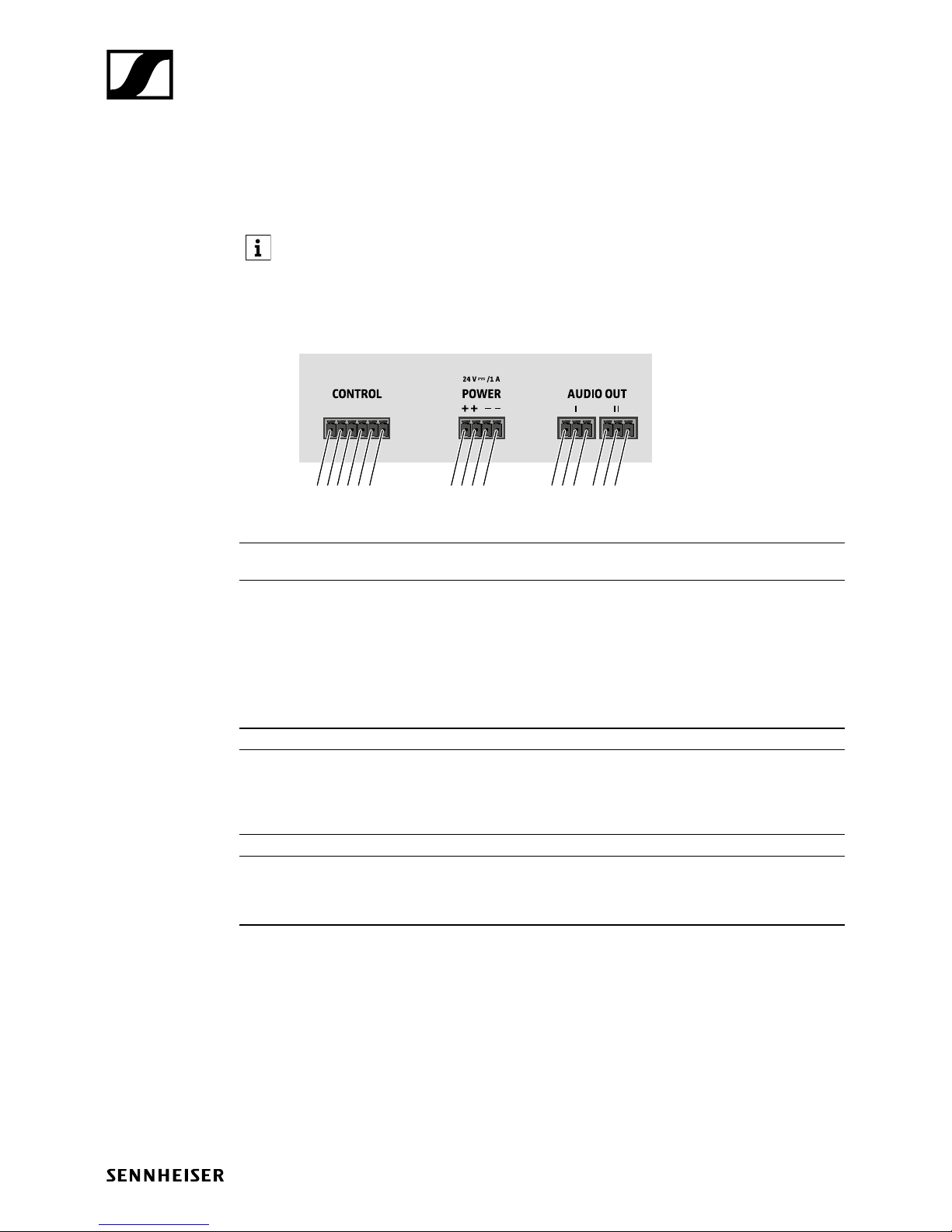
Pin allocation of the terminals of the SL Ceiling Mic
1 2 3 1 2 3
1 2 3 4
1 2 3 4 5 6
CONTROL terminal Logic port for connecting the SL TeamConnect CB1 or a media
control system.
1
2
3
4
5
6
Pin allocation:
+24 V
COM
On status
Hook status
Mute status
Ground
Controls the LED status indication (On/Hook/Status)
POWER terminal Power supply 24 V DC
1
2
3
4
Pin allocation:
+24 V
+24 V
Ground
Ground
AUDIO OUT terminals Parallel audio outputs of the microphone signal
1
2
3
Pin allocation:
Audio +
Audio Ground
 Loading...