

Sennheiser SKM 300 G4-S-AW+, SKM 500 G4-AW+, EW 500 G4-965-AW+, EW 500 G4-MKE2-AW+, EW 500 G4-945-AW+ User Manual
...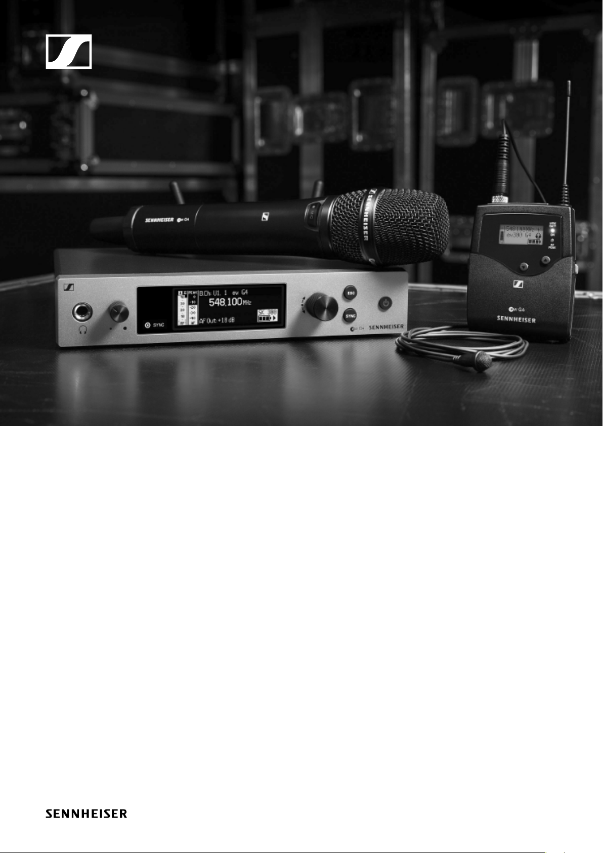
evolution wireless G4
300 series / 500 series
Instruction Manual
Sennheiser electronic GmbH & Co. KG
Am Labor 1, 30900 Wedemark, Germany, www.sennheiser.com
ew 300-500 G4 - v1.1

Overview 8
ew 300-500 G4 series products 9
EM 300-500 G4 rack receiver 10
SKM 300 G4 handheld transmitter 11
SK 300 G4 bodypack transmitter 12
SKM 500 G4 handheld transmitter 13
SK 500 G4 bodypack transmitter 14
Accessories 15
Microphones and cables 15
Microphone modules 15
Headset and Lavalier microphones 16
Line/instrument cables 16
Rechargeable battery and charger 17
BA 2015 rechargeable battery 17
L 2015 charger 17
LA 2 charging adapter 18
Accessories for rack mounting 19
GA 3 rack mount kit 19
AM 2 antenna front mounting kit 19
Antennas and accessories 20
Omni-directional antennas 20
Directional antennas 20
Antenna splitter 20
Antenna amplifiers 20
Additional accessories 21
Color labeling set 21
Microphone clamp 21
MUTE switch 21
The frequency bank system 22
Installing and starting up ew 300-500 G4 series devices 23
Installing the EM 300-500 G4 25
Connectors on the rear of the device 25
Product overview for the rear of the EM 300-500 G4 25
Connecting/disconnecting the EM 300-500 G4 to/from
the power supply system 26
Creating a data network 27
Outputting audio signals 28
Connecting antennas 29
Installing the EM 300-500 G4 in a rack 30
Mounting a single receiver in a rack 31
Mounting two receivers side by side in a rack 32
Installing the SKM 300 G4 33
Inserting and removing the batteries/rechargeable batteries 33
Battery status 34
Replacing the microphone module 35
Changing the colored ring 36
Installing the SKM 500 G4 37
Inserting and removing the batteries/rechargeable bat-
1

teries 37
Battery status 38
Replacing the microphone module 39
Changing the colored ring 40
Installing the SK 300 G4 41
Inserting and removing the batteries/rechargeable batteries 41
Battery status 42
Connecting a microphone to the SK 300 G4 43
Connecting an instrument or line source to the
SK 300 G4 44
Connecting the RMS 1 mute switch to the SK 300 45
Attaching the bodypack transmitter to clothing 46
Installing the SK 500 G4 47
Inserting and removing the batteries/rechargeable batteries 47
Battery status 48
Connecting a microphone to the SK 500 G4 49
Connecting an instrument or line source to the
SK 500 G4 50
Attaching the bodypack transmitter to clothing 51
Installing the ASA 214 52
Connectors on the rear of the device 52
Product overview for the rear side of the ASA 214 52
Connecting/disconnecting the ASA 214 to/from the power supply system 53
Connecting receivers to the ASA 214 54
Connecting antennas 55
Connecting remote antennas 55
Connecting rod antennas 55
Information on antenna amplifiers and cable lengths 56
Configuring multi-channel systems 57
Option 1: Two antennas supply a 4-channel system 57
Option 2: Two 4-channel systems are interconnected
58
Option 3: Two antennas supply a 8-channel system 58
Installing the ASA 214 in a rack 59
Mounting a single antenna splitter in a rack 60
Mounting two antenna splitters side by side in a rack
62
Using ew 300–500 G4 series devices 63
Using the EM 300-500 G4 66
Operating elements on the front of the device 66
Product overview for the front of the EM 300-500 G4 66
Switching the EM 300-500 G4 on and off 67
Muting the audio output 68
Using the headphone output 69
Lock-off function 70
Displays on the EM 300-500 G4 display panel 71
Buttons for navigating through the menu 72
Home screen 73
2

Receiver Parameters standard display 74
Transmitter Parameters standard display 75
Soundcheck standard display 76
RF Min 76
RF Max 76
AF Max 76
Setting options in the menu 77
Menu structure 78
Squelch menu item 79
Easy Setup menu item 81
Scan New List 81
Current List 82
Reset 82
Performing multi-channel frequency setup 82
Frequency Preset menu item 85
Name menu item 86
AF Out menu item 87
Equalizer menu item 88
Auto Lock menu item 89
Advanced menu item 90
Advanced -> Tune menu item 91
Only adjusting the frequency 91
Setting the channel and frequency 91
Advanced -> Sync Settings menu item 92
Advanced -> Pilot Tone menu item 92
Advanced -> Fullscreen Warnings menu item 93
Advanced -> Brightness menu item 93
Advanced -> Reset menu item 94
Advanced -> IP Address menu item 94
Advanced -> Software Revision menu item 94
Using the SKM 300 G4 95
Operating elements of the SKM 300 G4 handheld transmitter 95
Switching the SKM 300 G4 handheld transmitter on and
off 96
Muting the handheld transmitter (AF mute) 97
Deactivating the RF signal (RF mute) 98
Deactivating the RF signal with the MIC button 98
Deactivating the RF signal with the ON/OFF button 99
Lock-off function 100
Displays on the SKM 300 G4 handheld transmitter display panel 101
Select a standard display 102
Buttons for navigating the SKM 300 G4 menu 103
Navigating through the menu 103
Making changes in a menu item 103
Setting options in the menu 104
Sensitivity menu item 105
Frequency Preset menu item 105
Name menu item 106
Auto Lock menu item 106
Advanced menu item 107
3

Advanced > Tune menu item 108
Only adjusting the frequency 108
Setting the channel and frequency 108
Advanced > Mute Mode menu item 109
Advanced > MIC LED menu item 110
Advanced > RF Power menu item 111
Advanced > Pilot Tone menu item 111
Advanced > LCD Contrast menu item 111
Advanced > Reset menu item 112
Advanced > Software Revision menu item 112
Using the SKM 500 G4 113
Operating elements of the SKM 500 G4 handheld transmitter 113
Switching the SKM 500 G4 handheld transmitter on and
off 114
Muting the handheld transmitter (AF mute) 115
Deactivating the RF signal (RF mute) 115
Lock-off function 116
Displays on the SKM 500 G4 handheld transmitter display panel 117
Select a standard display 118
Buttons for navigating the SKM 500 G4 menu 119
Navigating through the menu 119
Making changes in a menu item 119
Setting options in the menu 120
Sensitivity menu item 121
Frequency Preset menu item 121
Name menu item 122
Auto Lock menu item 122
Advanced menu item 123
Advanced > Tune menu item 124
Only adjusting the frequency 124
Setting the channel and frequency 124
Advanced > RF Power menu item 125
Advanced > Pilot Tone menu item 125
Advanced > LCD Contrast menu item 126
Advanced > Reset menu item 126
Advanced > Software Revision menu item 126
Using the SK 300 G4 127
Operating elements of the SK 300 G4 bodypack transmitter 127
Switching the SK 300 G4 bodypack transmitter on and
off 129
Muting the bodypack transmitter (AF mute) 130
Muting the audio signal with the MUTE switch 130
Muting the audio signal with the RMS 1 remote mute
switch 130
Deactivating the RF signal (RF mute) 131
Deactivating the RF signal with the MUTE switch 131
Deactivating the RF signal with the ON/OFF button 132
Deactivating the RF signal with the RMS 1 remote mute
4

switch 132
Using the SK 300 G4 with the RMS 1 remote mute switch
133
Lock-off function 134
Displays on the SK 300 G4 bodypack transmitter display
panel 135
Select a standard display 136
Buttons for navigating the SK 300 G4 menu 137
Navigating through the menu 137
Making changes in a menu item 137
Setting options in the menu 138
Sensitivity menu item 139
Frequency Preset menu item 139
Name menu item 140
Auto Lock menu item 140
Advanced menu item 141
Advanced > Tune menu item 142
Only adjusting the frequency 142
Setting the channel and frequency 142
Advanced > Mute Mode menu item 143
MUTE switch functions 143
Functions of the RMS 1 remote mute switch 143
Advanced > MIC LED menu item 144
Advanced > RF Power menu item 145
Advanced > Pilot Tone menu item 145
Advanced > LCD Contrast menu item 146
Advanced > Reset menu item 146
Advanced > Software Revision menu item 146
Using the SK 500 G4 147
Operating elements of the SK 500 G4 bodypack transmitter 147
Switching the SK 500 G4 bodypack transmitter on and
off 149
Muting the bodypack transmitter (AF mute) 150
Deactivating the RF signal (RF mute) 151
Deactivating the RF signal with the MUTE switch 151
Deactivating the RF signal with the ON/OFF button 152
Lock-off function 153
Displays on the SK 500 G4 bodypack transmitter display
panel 154
Select a standard display 155
Buttons for navigating the SK 500 G4 menu 156
Navigating through the menu 156
Making changes in a menu item 156
Setting options in the menu 157
Sensitivity menu item 158
Frequency Preset menu item 158
Name menu item 159
Auto Lock menu item 159
Advanced menu item 160
Advanced > Tune menu item 161
Only adjusting the frequency 161
5

Setting the channel and frequency 161
Advanced > Mute Mode menu item 162
Advanced > RF Power menu item 162
Advanced > Pilot Tone menu item 163
Advanced > LCD Contrast menu item 163
Advanced > Reset menu item 163
Advanced > Software Revision menu item 163
Establishing a radio link 164
Setting notes 164
Synchronizing devices 165
Using the ASA 214 167
Operating elements on the front of the device 167
Switching the ASA 214 on and off 167
Overview 168
Product variants 169
EM 300-500 G4 product variants 169
Made in Germany 169
Assembled in the USA 169
SKM 300 G4 product variants 170
Made in Germany 170
Assembled in the USA 170
SKM 500 G4 product variants 171
Made in Germany 171
Assembled in the USA 171
SK 300 G4 product variants 172
Made in Germany 172
Assembled in the USA 172
SK 500 G4 product variants 173
Made in Germany 173
Assembled in the USA 173
Frequency tables 174
Specifications 175
EM 300-500 G4 176
RF characteristics 176
AF characteristics 177
Overall device 177
SKM 300 G4 178
RF characteristics 178
AF characteristics 179
Overall device 179
SKM 500 G4 180
RF characteristics 180
AF characteristics 181
Overall device 181
SK 300 G4 182
RF characteristics 182
AF characteristics 183
Overall device 183
SK 500 G4 184
RF characteristics 184
6

AF characteristics 185
Overall device 185
ASA 214 186
Specifications 186
Block diagram 187
Pin assignment 188
3.5 mm stereo jack plug 188
3.5 mm mic jack plug 188
3.5 mm line jack plug 188
6.3 mm stereo jack plug, balanced (audio in/loop out)
188
6.3 mm mono jack plug, unbalanced 189
6.3 mm stereo jack plug for headphone jack 189
XLR-3 plug, balanced 189
Hollow jack plug for power supply 189
Cleaning and maintenance 190
Cleaning the sound inlet basket of the microphone mo-
dule 190
Contact 192
Instruction manual as a PDF 192
Customer service 192
Feedback 192
7
PRODUCT INFORMATION
Overview
Overview
You can find information about the individual products in the ew 300500 G4 series under “ew 300-500 G4 series products”.
For information about the available accessories, see “Accessories”.
You can find information about the ew 300-500 G4 series frequency bank
system under “The frequency bank system”.
8

ew 300-500 G4 series products
ew 300-500 G4 series products
Click the name of the particular product to learn more about it.
You can also find more information here:
• A variety of frequency variants are available from the individual products. You can find more information under “Product variants”.
• You can find technical specifications about the individual products under “Specifications”.
• You can find information about installing the products under “Installing
and starting up ew 300-500 G4 series devices”.
• You can find information about operating the products under “Using
ew 300–500 G4 series devices”.
9
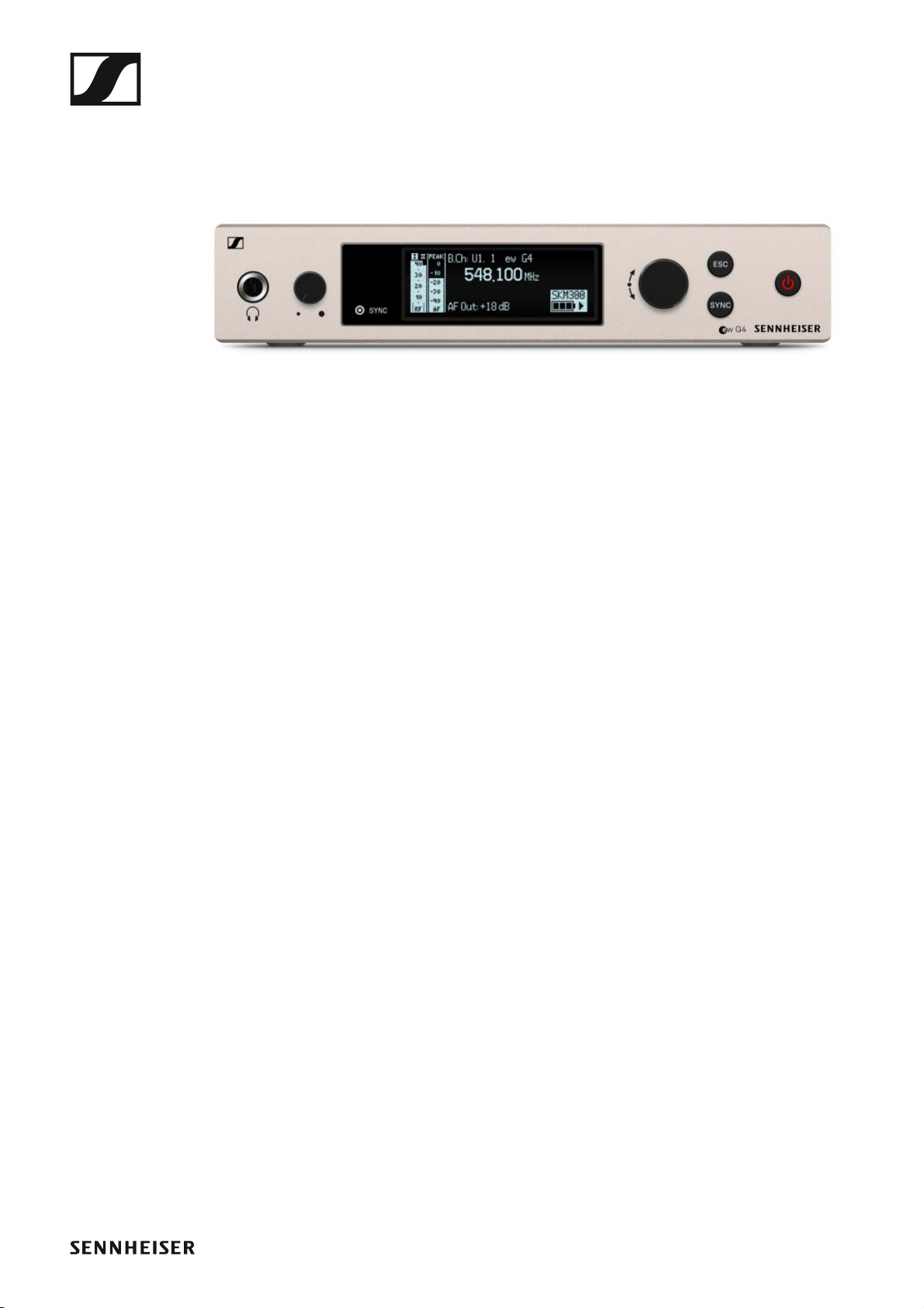
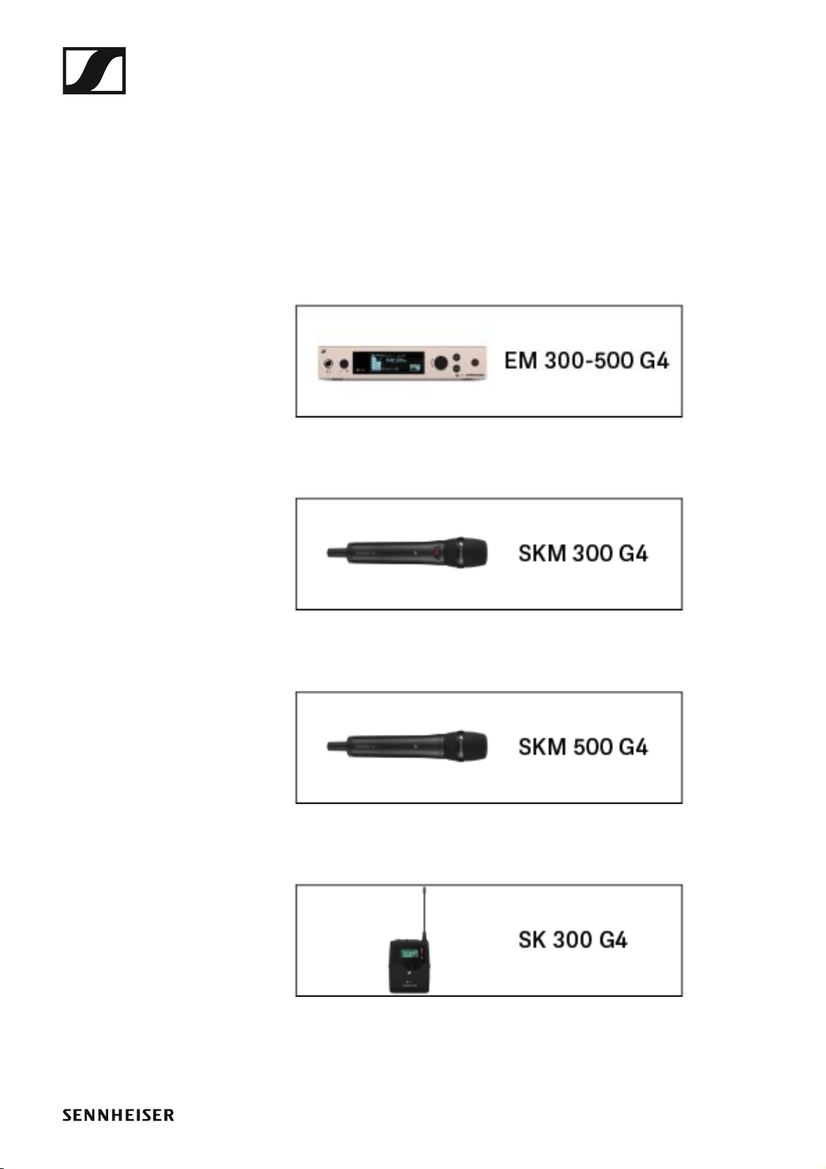
EM 300-500 G4 rack receiver
►
You can find more detailed information about the EM 300-500 G4 in the
following sections:
• Installation and Startup: “Installing the EM 300-500 G4”
• Operation: “Using the EM 300-500 G4”
• Technical Data: “EM 300-500 G4”
10
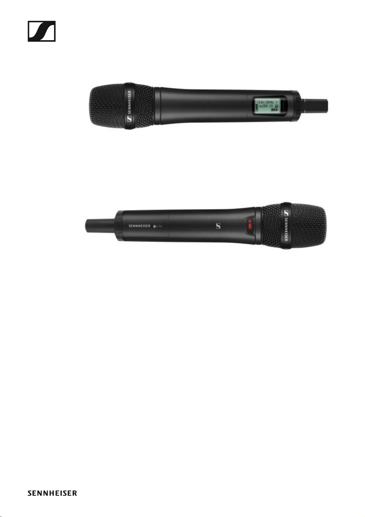
SKM 300 G4 handheld transmitter
►
►
You can find more detailed information about the SKM 300 G4 in the following sections:
• Installation and Startup: “Installing the SKM 300 G4”
• Operation: “Using the SKM 300 G4”
• Technical Data: “SKM 300 G4”
11
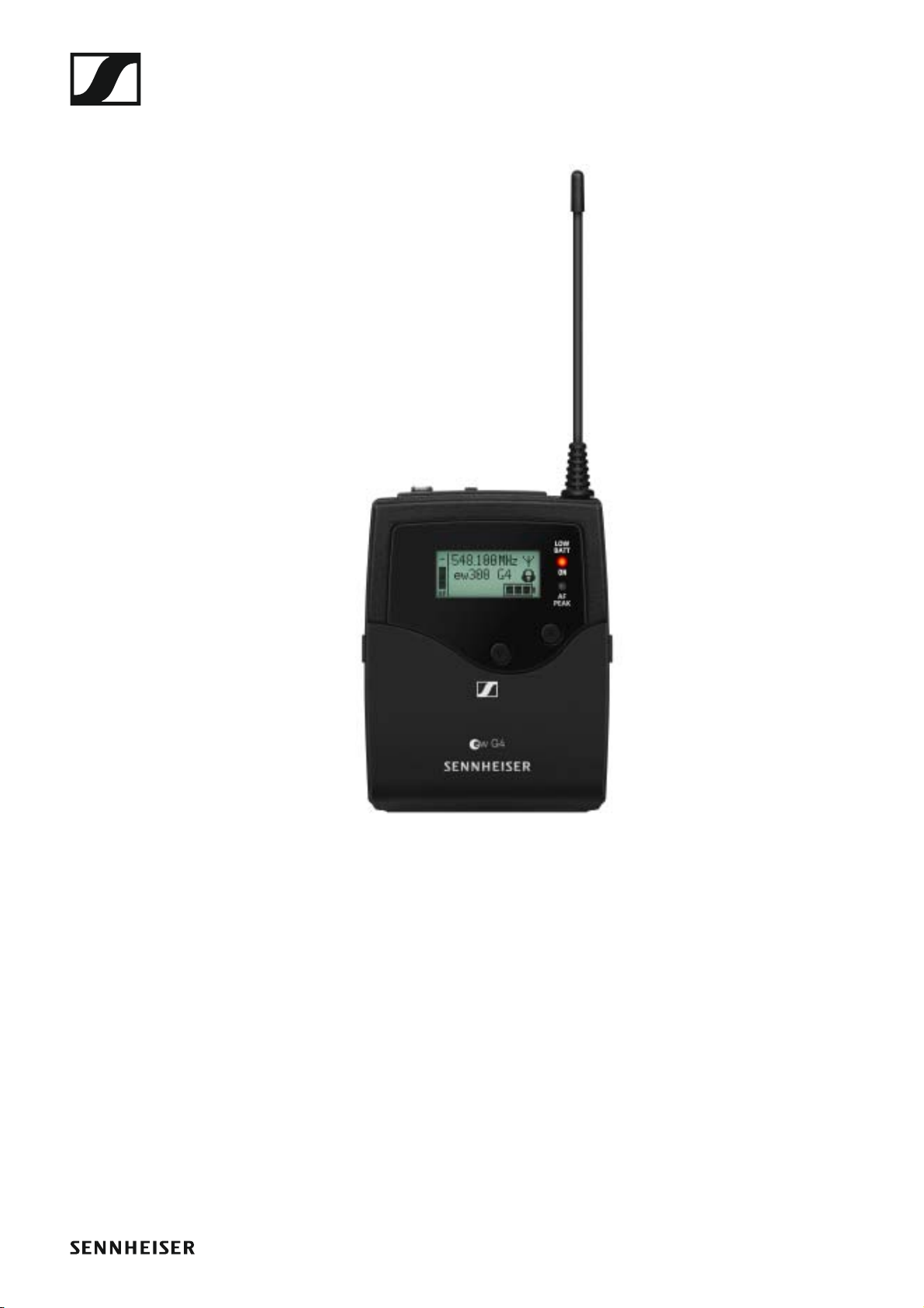
SK 300 G4 bodypack transmitter
You can find more detailed information about the SK 300 G4 in the following sections:
• Installation: “Installing the SK 300 G4”
• Operation: “Using the SK 300 G4”
• Technical Data: “SK 300 G4”
12
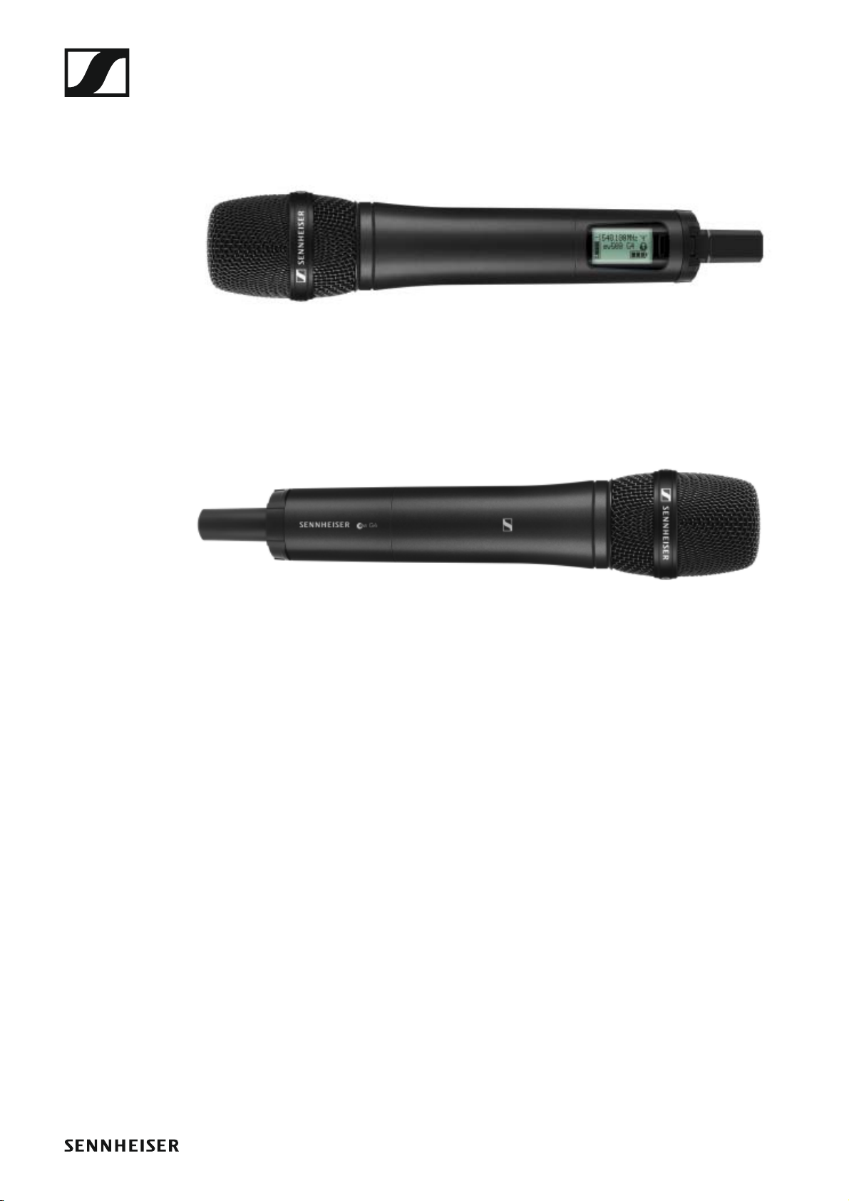
SKM 500 G4 handheld transmitter
►
►
You can find more detailed information about the SKM 500 G4 in the following sections:
• Installation and Startup: “Installing the SKM 500 G4”
• Operation: “Using the SKM 500 G4”
• Technical Data: “SKM 500 G4”
13
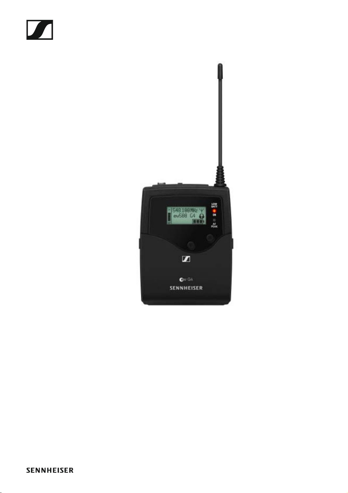
SK 500 G4 bodypack transmitter
►
You can find more detailed information about the SK 500 G4 in the following sections:
• Installation and Startup: “Installing the SK 500 G4”
• Operation: “Using the SK 500 G4”
• Technical Data: “SK 500 G4”
14

Accessories
Accessories
A variety of accessories are available for the ew 300-500 G4 series.
Microphones and cables
Microphone modules
We recommend using the following microphone modules with the
SKM 300 G4 and SKM 500 G4 handheld transmitters.
►
Module Features Article
no.
MMD 835-1 BK Dynamic, cardioid, black 502575
MMD 845-1 BK Dynamic, super-cardioid, black 502576
MME 865-1 BK Capacitor, super-cardioid, black 502581
MMD 935-1 BK Dynamic, cardioid, black 502577
MMD 945-1 BK Dynamic, super-cardioid, black 502579
MMK 965-1 BK Capacitor, switchable
Cardioid/super-cardioid, black
MMK 965-1 NI Capacitor, switchable
Cardioid/super-cardioid, nickel
MD 9235 BK Dynamic, cardioid, black 502585
MD 9235 NI Dynamic, cardioid, black 502586
MD 9235 NI/BK Dynamic, cardioid, nickel/black 502591
Neumann
KK 204
Neumann
KK 204 BK
Neumann
KK 205
Neumann
KK 205 BK
Capacitor, cardioid, nickel 008651
Capacitor, cardioid, black 008652
Capacitor, super-cardioid, nickel 008653
Capacitor, super-cardioid, black 008654
502582
502584
You can find more information about the individual microphone modules on their respective product pages at www.sennheiser.com.
15

Accessories
Headset and Lavalier microphones
We recommend using the following Lavalier microphones and headset microphones with the SK 300 G4 and SK 500 G4 bodypack transmitters.
►
Microphone Features Article
no.
ME 2-II Lavalier microphone, omni-direc-
tional, black
ME 3-II Headset microphone, cardioid,
black
ME 4-N Lavalier microphone, cardioid,
black
MKE 1-ew Lavalier microphone, omni-direc-
tional, black
MKE 1-ew-3 Lavalier microphone, omni-direc-
tional, beige
MKE 2-ew Gold Lavalier microphone, omni-direc-
tional, black
MKE 2 ew-3 Gold Lavalier microphone, omni-direc-
tional, beige
MKE 40-ew Lavalier microphone, cardioid,
black
SL Headmic 1 BE Headband microphone, omni-di-
rectional,
beige
507437
506295
005020
502876
502879
009831
009832
500527
506272
SL Headmic 1 BK Headband microphone, omni-di-
506271
rectional,
black
SL Headmic 1 SB Headband microphone, omni-di-
506904
rectional,
silver
You can find more information about the individual microphones on
their respective product pages at www.sennheiser.com.
Line/instrument cables
The following cables are available to connect instruments and line sources
to the SK 300 G4 and SK 500 G4 bodypack transmitters:
• Sennheiser CL 2
Line cable with XLR-3F plug on lockable 3.5 mm jack plug, article no.
004840
• Sennheiser Ci 1-N
Guitar cable with 6.3 mm jack plug on lockable 3.5 mm jack plug, article
no. 005021
16
Accessories
Rechargeable battery and charger
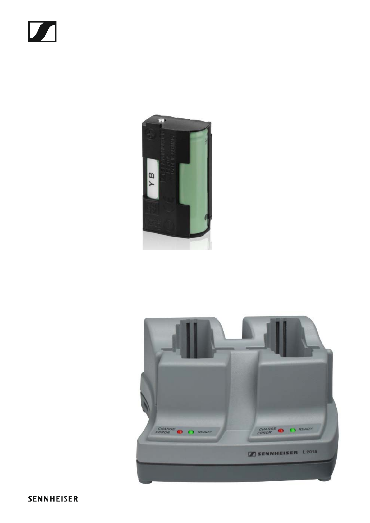
BA 2015 rechargeable battery
The BA 2015 rechargeable battery is designed for use with evolution wireless G4 series handheld transmitters, bodypack transmitters and
bodypack receivers.
Article no. 009950
►
L2015 charger
The BA 2015 rechargeable battery can be charged in the L 2015 charger on
its own or inside of the bodypack transmitter/bodypack receiver.
Article no. 009828
►
17

Accessories
LA 2 charging adapter
Charging adapter for L 2015 charger for charging SKM G4 handheld transmitters with installed BA 2015 rechargeable battery.
Article no. 503162
►
18
Accessories
Accessories for rack mounting
GA 3 rack mount kit
19” rack adapter for mounting the EM 100 G4, EM 300 G4, EM 500 G4 or
SR 300 IEM G4 in a 19” rack.
Article no. 503167
►
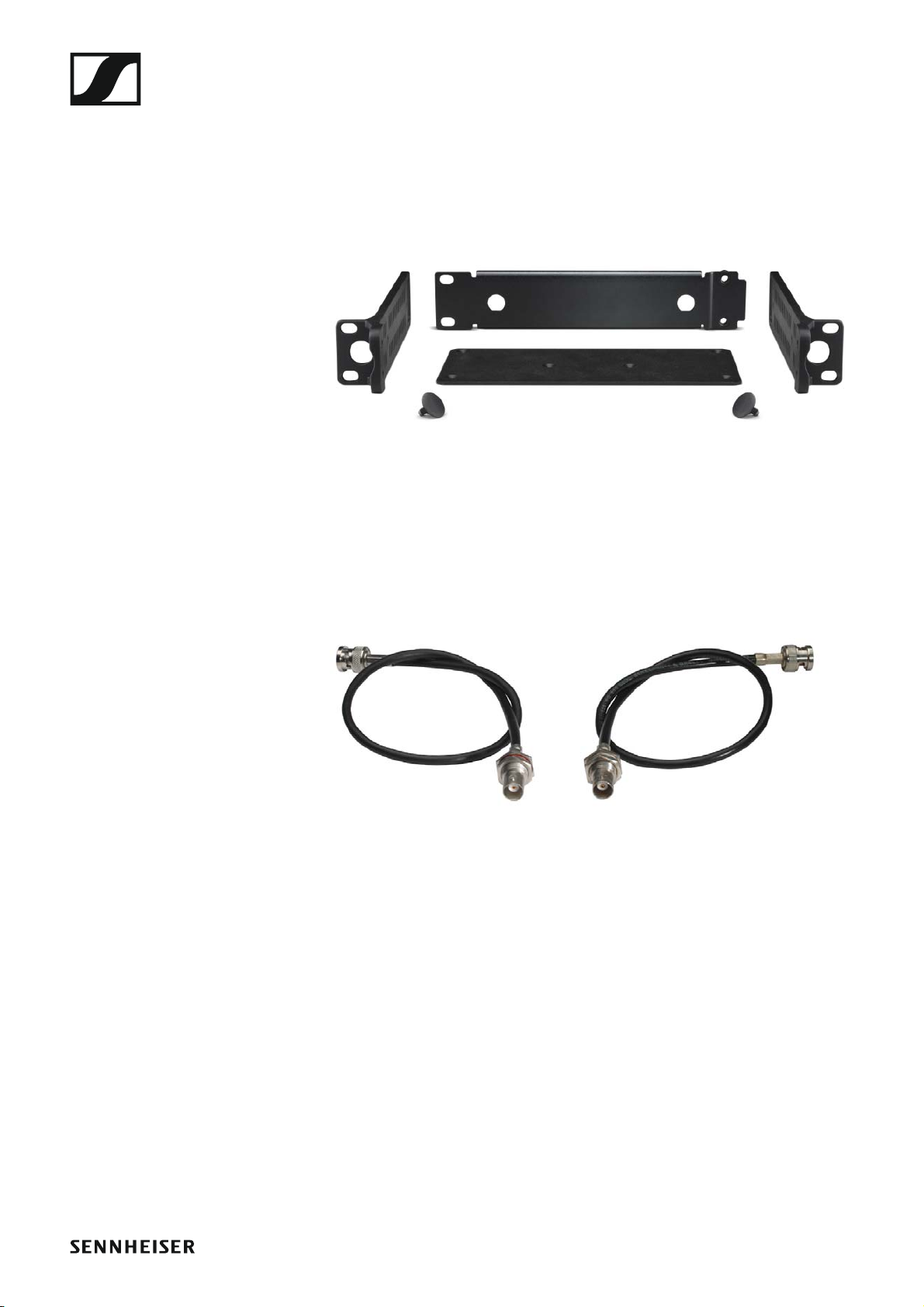
AM 2 antenna front mounting kit
Antenna front mounting kit for installing antenna connections on the front
of the rack when using the EM 100 G4, EM 300 G4, EM 500 G4 or
SR 300 IEM G4 together with the GA 3 rack mounting kit.
Article no. 009912
►
►
19
Accessories
Antennas and accessories
The following antenna components are available as accessory parts.
Omni-directional antennas
• A 1031-U, passive omni-directional antenna, article no. 004645
Directional antennas
• A 2003 UHF, passive directional antenna, article no. 003658
Antenna splitter
►
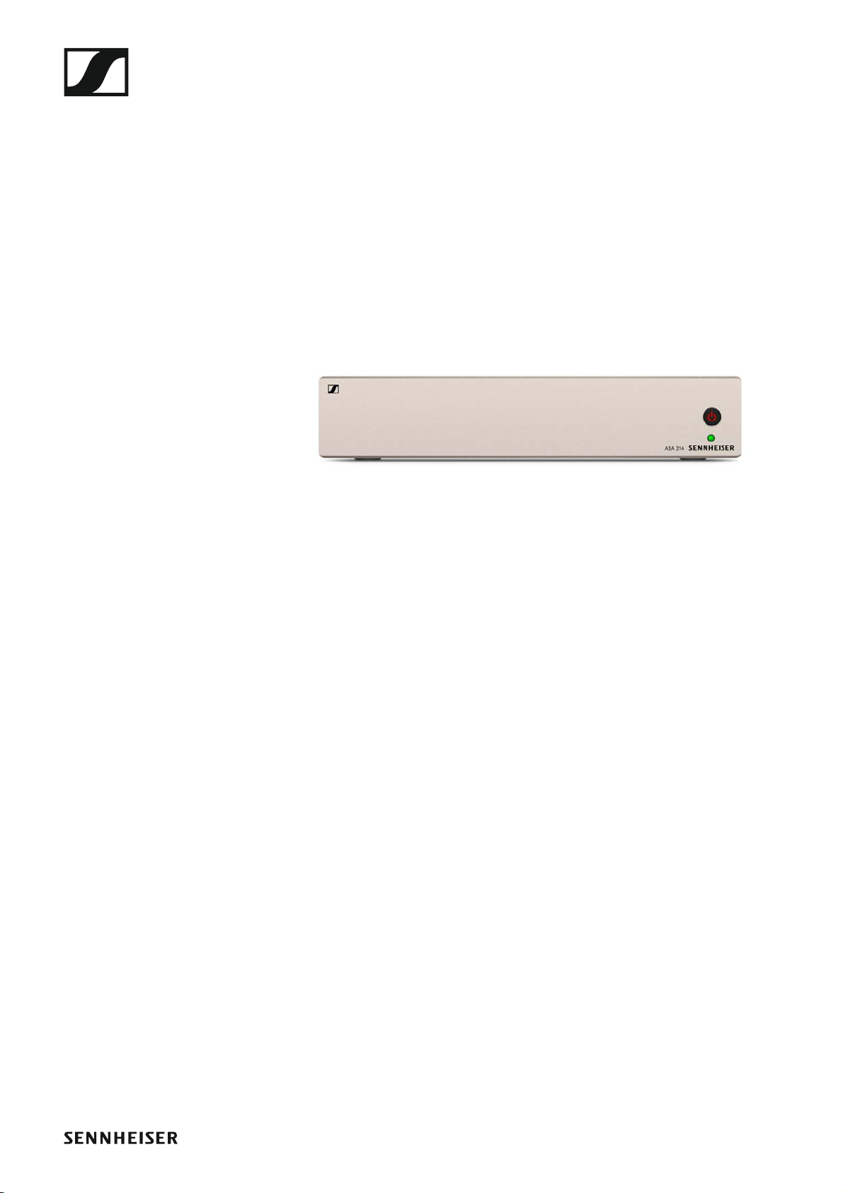
• ASA 214, active antenna splitter 2×1:4
• ASA 214-UHF variant, 470 – 870 MHz, article no. 508241
Antenna amplifiers
• AB 3700, broadband antenna amplifier, article no. 502196
• AB 4, antenna amplifier, up to 88 MHz bandwidth
Available from the end of 2018
20

Accessories
Additional accessories
Color labeling set
• KEN 2, color labeling set for SKM handheld transmitters, article no.
530195
►
Microphone clamp
• MZQ 1, microphone clamp for SKM handheld transmitters, article no.
076670
►
MUTE switch
• RMS 1, remote mute switch for SK 300 G4, article no. 503164
►
21
The frequency bank system
The frequency bank system
There are different frequency ranges in the UHF band available for transmission.
The following frequency ranges are available for the ew 300-
500 G4 series:
• Aw+ range: 470 – 558 MHz
• AS range: 520 – 558 MHz
• Gw1 range: 558 – 608 MHz
• Gw range: 558 – 626 MHz
• GBw range: 606 – 678 MHz
• Bw range: 526 – 698 MHz
• Cw range: 718 – 790 MHz
• Dw range: 790 – 865 MHz
• JB range: 806 – 810 MHz
• K+ range: 925 – 937.5 MHz
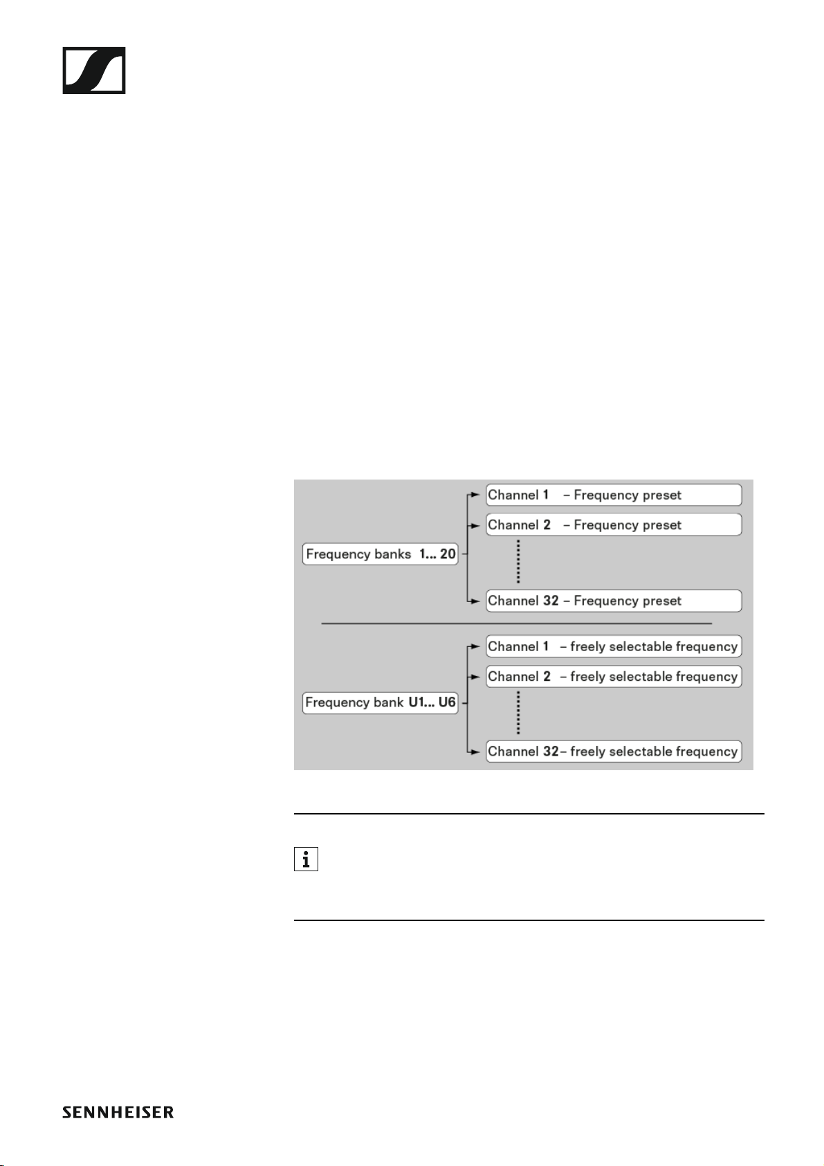
Every frequency range has 26 frequency banks with up to 32 channels:
►
You can find information about the frequency presets in the frequency tables of the respective frequency ranges under “Frequency tables”.
22
Installing and starting up ew 300-500 G4 series devices
INSTALLATION
Installing and starting up ew 300500 G4 series devices
You can find information about installing and connecting ew 300500 G4 series devices in the following sections.
• EM 300-500 G4 rack receiver >> “Installing the EM 300-500 G4”
• SKM 300 G4 handheld transmitter >> “Installing the SKM 300 G4”
• SKM 500 G4 handheld transmitter >> “Installing the SKM 500 G4”
• SK 300 G4 bodypack transmitter >> “Installing the SK 300 G4”
23
Installing and starting up ew 300-500 G4 series devices
• SK 500 G4 bodypack transmitter >> “Installing the SK 500 G4”
• ASA 214 antenna splitter>> “Installing the ASA 214”
You can find information about operating the products under “Using
ew 300–500 G4 series devices”.
24
Installing the EM 300-500 G4
Installing the EM 300-500 G4
These sections contain detailed information about installing and starting
up the EM 300-500 G4.
You can find information about operating the EM 300-500 G4 under “Using
the EM 300-500 G4”.
Connectors on the rear of the device
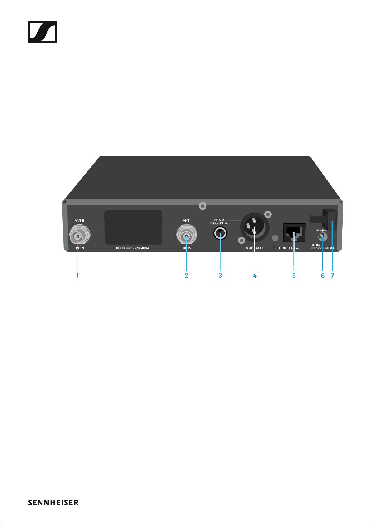
Product overview for the rear of the EM 300-500 G4
►
1 BNC socket, antenna input II (ANT II) with remote power supply unit
• See “Connecting antennas”
2 BNC socket, antenna input I (ANT I) with remote power supply unit
• See “Connecting antennas”
3 6.3 mm jack socket for audio output, unbalanced (AF OUT UNBAL)
• See “Outputting audio signals”
4 XLR-3 socket for audio output, balanced (AF OUT BAL)
• See “Outputting audio signals”
5 LAN connection socket (ETHERNET RJ 45)
• See “Creating a data network”
6 Connecting cables for the power supply unit (DC IN)
• See “Connecting/disconnecting the EM 300-500 G4 to/from the
power supply system”
7 Strain relief for the cable of the power supply unit
• See “Connecting/disconnecting the EM 300-500 G4 to/from the
power supply system”
25
Installing the EM 300-500 G4
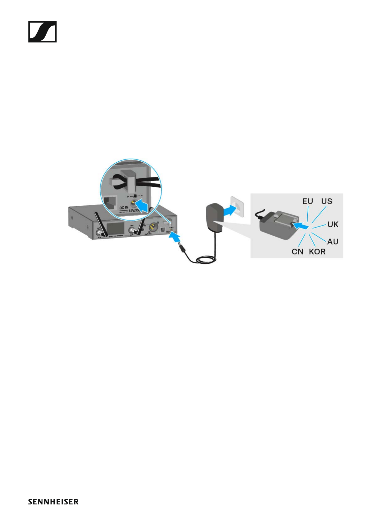
Connecting/disconnecting the EM 300-500 G4 to/ from the power supply system
Only use the supplied power supply unit. It is designed for your receiver
and ensures safe operation.
To connect the EM 300-500 G4 to the power supply system:
▷ Insert the plug of the power supply unit into the DC IN socket of the re-
ceiver.
▷ Pass the cable of the power supply unit through the cable grip.
▷ Slide the supplied country adapter onto the power supply unit.
▷ Plug the power supply unit into the wall socket.
To completely disconnect the EM 300-500 G4 from the power supply system:
▷ Unplug the power supply unit from the wall socket.
▷ Unplug the power supply unit from the DC IN socket of the receiver.
26

Installing the EM 300-500 G4
Creating a data network
You can monitor and control one or more EM 300-500 G4s via a network
connection using Sennheiser Wireless Systems Manager (WSM) software.
Automatic frequency setup can also be performed over the network
without the WSM software. See “Easy Setup menu item”.
To connect the EM 300-500 G4 to a network:
▷ Connect a network cable with an RJ-45 connector (to the Ethernet
socket on the rear side of the EM 300-500 G4.
▷ Connect the other end of the network cable to a network switch.
►
For more information about controlling devices via the Sennheiser
Wireless Systems Manager (WSM) software, refer to the instruction manual for the software. You can download the software here:
www.sennheiser.com/wsm
27
Installing the EM 300-500 G4
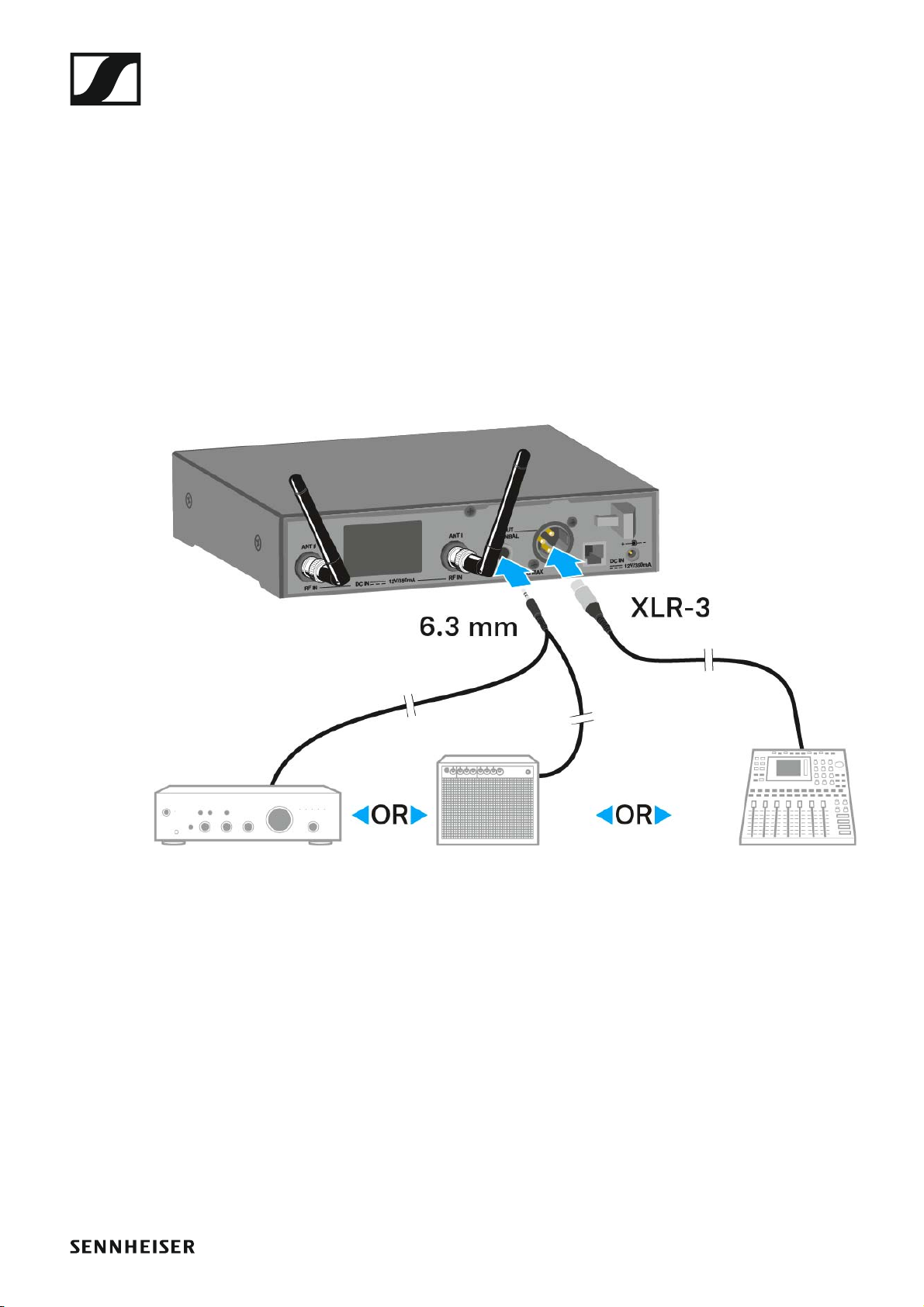
Outputting audio signals
The EM 300-500 G4 has a balanced XLR-3M output socket and an unbalanced 6.3 mm jack output socket.
▷ Always use only one of the two BAL AF OUT output sockets for each
channel.
To connect an XLR cable:
▷ Plug the XLR cable into the AF OUT BAL socket of the EM 300-500 G4.
To connect a jack cable:
▷ Plug the jack cable into the AF OUT UNBAL socket of the EM 300-
500 G4.
28
Installing the EM 300-500 G4
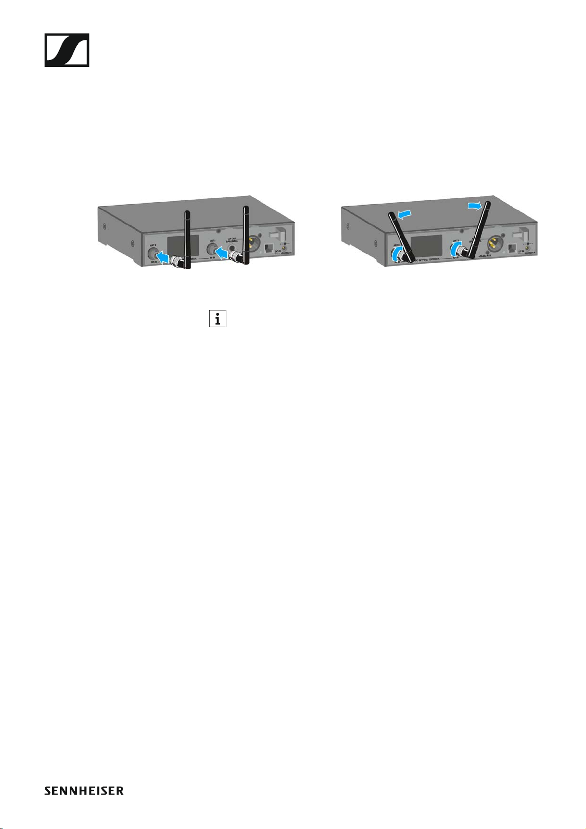
Connecting antennas
To connect the supplied rod antennas:
▷ Connect the first rod antenna to the ANT I socket on the rear side of the
EM 300-500 G4.
▷ Connect the second rod antenna to the ANT II socket on the rear side
of the EM 300-500 G4.
▷ Gently angle the rod antennas to the left and right as shown in the fig-
ure.
If you are using more than one receiver, we recommend using remote
antennas and, as needed, Sennheiser antenna accessories. For more
information, visit the ew G4 product page at www.sennheiser.com.
29
 Loading...