

Page 1

DS220
DS320
Screw Fastening System Attachment
Operating Instructions and
Parts Reference Guide
Instrucciones de Operacion y
Guía de referencia de piezas
Mode d’Emploi et
Pièces Guide de référence
Senco Brands, Inc.
4270 Ivy Pointe Blvd.
Cincinnati, OH 45245
1-800-543-4596
www.senco.com
Warnings for the safe use of this tool are included in this manual.
Los avisos para el uso seguro de esta herramienta están incluidos en este manual.
Les consignes pour l’utilisation en toute sécurité de cet outil se trouvent dans ce manuel.
NFD06W • Revised April 24, 2014 (Replaces 8/29/2013)
© 2014 by Senco Brands, Inc.
Page 2
EMPLOYER’S
RESPONSIBILITIES
Employer must enforce compliance
with the safety warnings and all other
instructions which accompany this tool
as shipped from the
manufacturer.
Keep this manual available
for use by all people
assigned to the use of this
tool.
For personal safety and
proper operation of this
tool, read and understand
all of these instructions
carefully.
TABLE OF CONTENTS TABLA DES MATERIAS TABLE DES MATIERES
RESPONSABILIDADES DEL
EMPLEADOR
El empleador debe hacer cumplir las
advertencias de seguridad y todas las
otras instrucciones que acompañan a
esta herramienta como se la despacha
desde el fabricante.
Mantenga este manual disponible
para que lo usen todas
las personas destinadas a hacer
uso de esta herramienta.
Por razones de seguridad personal
y la adecuada operación de esta
herramienta, lea y comprenda todas
estas instrucciones cuidadosamente.
RESPONSABILITES DE
L’EMPLOYEUR
L’employeur doit faire appliquer
les consignes de sécurité et toutes les
autres instructions qui accompagnent
cet outil tel qu’il est
livré par son constructeur.
Ayez ce manuel à la disposition de
toutes les personnes chargées
d’utiliser cet outil.
Pour assurer la sécurité
personnelle et le bon
emploi de cet outil, lisez et
assimilez soigneusement
toutes ces instructions.
Safety Warnings..................3 - 5
Tool Use ..............................6 - 11
Accessories........................11- 14
Technical Specications.....14
Troubleshooting..................15 - 17
Parts Reference Guide........18 - 19
Limited Warranty.................20
Avisos de Seguridad..................3 - 5
Use de la Herramienta...............6 - 11
Accesorios................................ 11- 14
Especicaciones Tecnicas.........14
Identicación de Fallas............. 15 - 17
Guía de referencia de piezas.....18 - 19
Limited Warranty...................... 20
Avertissements de sécurité........3 - 5
Utilisation d l’Outil.......................6 - 11
Accessoires...............................11- 14
Specications Techniques.........14
Dépannage.............................. 15 - 17
Pièces Guide de référence........18 - 19
Limited Warranty...................... 20
2
Page 3
SAFETY WARNINGS AVISOS
WARNING!
• Read all safety warnings and
all instructions. Failure to follow
the warnings and instructions may
result in electric shock, re and/or
serious injury.
SAVE ALL WARNINGS AND
INSTRUCTIONS FOR FUTURE
REFERENCE
• The term “power tool” in the
warnings refers to your mainsoperated (corded) power tool or
battery-operated (cordless) power
tool.
WORK AREA SAFETY
• Keep your work area clean and
well lit. Cluttered or dark areas
invite accidents.
• Lea todas las advertencias
de seguridad y todas las
instrucciones. No respetar
advertencias e instrucciones,
puede resultar en descargas
eléctricas, incendios y/o lesiones
graves.
ADVERTENCIAS E INSTRUCCIONES
PARA SU REFERENCIA FUTURA
• El término “herramienta eléctrica’’
en las advertencias se reere a
la herramienta eléctrica operada
con el suministro eléctrico (con
cable) o a la herramienta eléctrica
operada con la batería (sin
cable).
• Mantenga la zona de
trabajo limpia y en buenas
condiciones. Los bancos
de trabajo desordenados y
los lugares oscuros son una
invitación a un accidente.
DE SEGURIDAD
ADVERTENCIA!
GUARDE TODAS LAS
ZONA DE TRABAJO
AVERTISSEMENTS
DE SÉCURITÉ
AVERTISSEMENT!
• Lisez toutes les consignes
et instructions relatives à la
sécurité. Le non-respect des
avertissements et des instructions
pourrait causer des chocs
électriques, un incendie et/ou des
blessures graves.
CONSERVEZ TOUS LES
AVERTISSEMENTS ET LES
INSTRUCTIONS AUX FINS DE
RÉFÉRENCE ULTÉRIEURE.
• L’expression “outil électrique”
utilisée dans les consignes fait
référence à votre outil électrique
alimenté sur secteur (avec l) ou
alimenté à l’aide de piles (sans l).
ZONE DE TRAVAIL
• Maintenez votre zone de travail
propre et bien éclairée. Des
établis en désordre et des zones
mal éclairées augmentent les
risques d’accident.
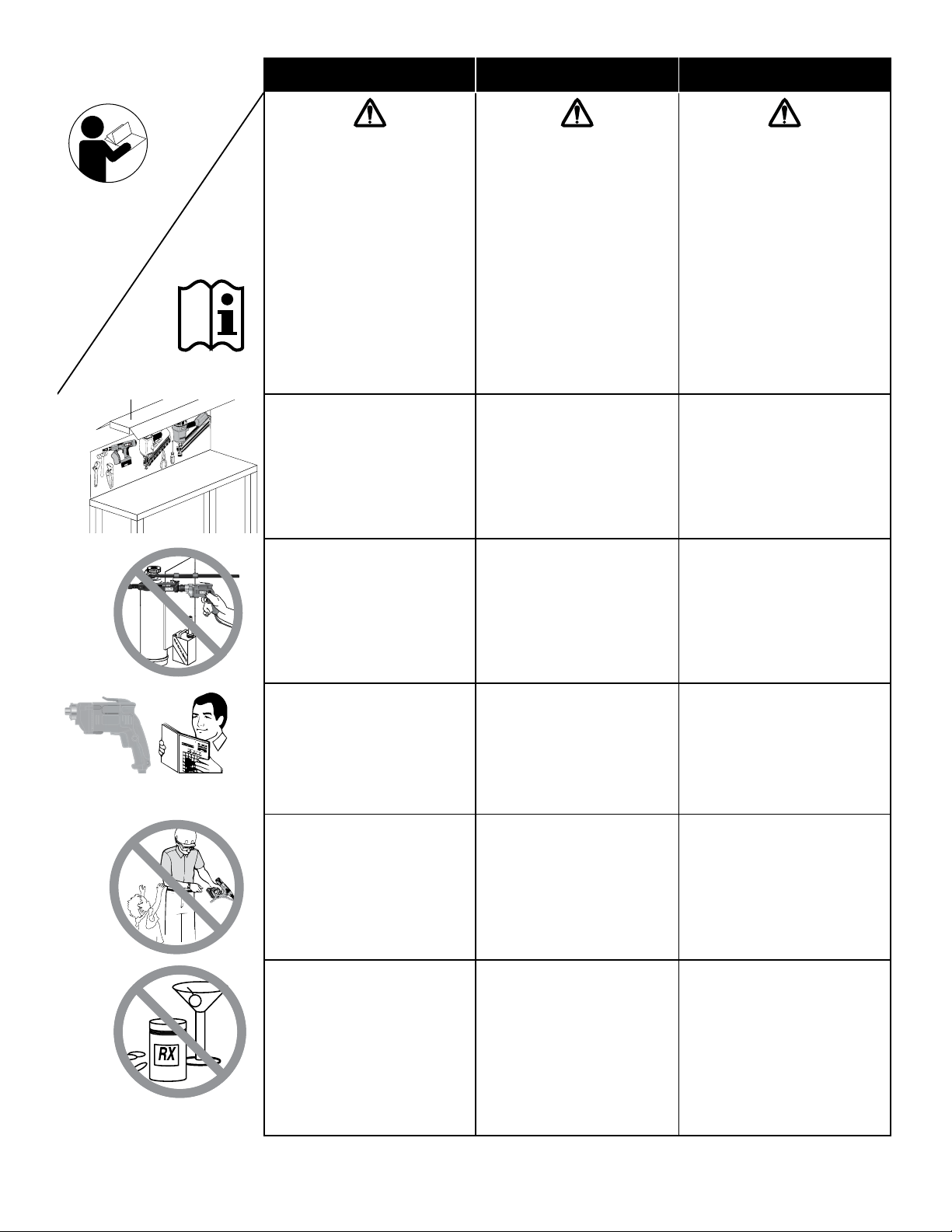
• Do not operate power tools in
explosive atmospheres, such
asinthepresenceofammable
liquids, gases, or dust. Power
tools create sparks which may
ignite the dust or fumes.
• The included auto-feed
screwdriver attachment can
be adapted to work with
several makes and models of
power screwdrivers. Refer to
the screwdriver manufacturer’s
operator’s manual for related safety
and operating instructions.
• Keep bystanders, minors,
and visitors away while you
are operating a power tool.
Distractions can cause you to lose
control.
PERSONAL SAFETY
• Stay alert, watch what you are
doing, and use common sense
when operating a power tool.
Do not use a power tool while you
are tired or under the inuence
of drugs, alcohol, or medication.
A moment of inattention while
operating power tools may result in
serious personal injury
• No haga funcionar
herramientas de motor en
atmósferas explosivas, tal
como en presencia de líquidos,
gasesopolvosinamables.
Las herramientas de motor
generan chispas que pueden
encender el polvo o los vapores.
• El accesorio incluido del
destornillador de carga
automática puede adaptarse para
funcionar con destornilladores
eléctricos de diferentes marcas
y modelos. Consulte el manual
de operación del fabricante para
conocer las instrucciones de
seguridad y funcionamiento del
destornillador.
• Mantengas los acompañantes,
menores y visitas alsjados
mientras usted utiliza la
herramienta de motor. Las
distracciones pueden hacer que
usted pierda el control.
SEGURIDAD PERSONAL
• Cuando utilice una herramienta
de motor, manténgase a;erta,
preste atención a lo que está
haciendo y aplique el sentido
común. No use la herramienta
cuando se sienta cansado o se
encuentre bajo los efectos de
drogas, alchol o medicamentos.
Un momento de falta de atención
mientras utiliza una herramienta
de motor puede ocasionar
lesiones graves.
• N’utilisez pas d’outillage
électrique dans un
environnement contenant des
produits explosifs comme des
liquidesinammables,gaz
ou poussières. De l’outillage
électrique génère des étincelles qui
peuvent enammer la poussière ou
les vapeurs.
• L’accessoire de tournevis à
alimentation automatique inclus
peut s’adapter pour travailler avec
plusieurs marques et modèles de
tournevis électriques. Consultez
le guide d’utilisation du fabricant
du tournevis pour obtenir les
consignes de sécurité et les
instructions d’utilisation relatives
à l’outil.
• Maintenez les spectateurs,
enfants et visiteurs à l’écart
lorsque vous utilisez de
l’outillage électrique. Toute
distraction risque de vous faire
perdre le contrôle de votre outil.
SÉCURITÉ CORPORELLE
• Soyez en bonne condition
physique, soyez attentif à ce
que vous faites et faites preuve
de bon sens lorsque vous
utilisez un outillage électrique.
N’utilisez pas votre outil si vous
êtes fatigué ou sous l’inuence de
drogues, alcool ou médicaments.
Un moment d’inattention lors de
l’utilisation d’un outillage électrique
peut être la cause de graves
blessures corporelles.
3
Page 4
SAFETY WARNINGS AVISOS
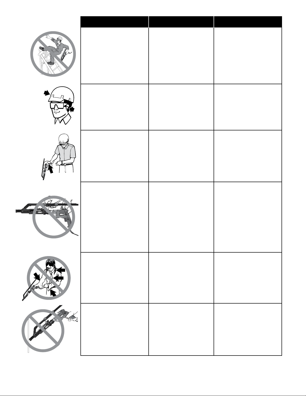
• Do not overreach. Keep proper
footing and balance at all times.
Proper footing and balance enable
better control of the tool in unexpected situations.
• No se estire para trabajar.
Mantenga en todo momento
una posición adecuada y el
equilibrio. La posición y el
equilibrio adecuados le permiten
contrilar mejor la herramienta
ante situaciones inesperadas.
DE SEGURIDAD
AVERTISSEMENTS
DE SÉCURITÉ
• Ne présumez pas de vos forces.
Restez bien stable et en équilibre
à tout moment. Une position
stable et bien équilibrée vous
permettra de mieux réagir à une
situation inattendue.
• Use personal protective
equipment. Always wear eye
protection. Protective equipment
such as dust mask, non-skid
safety shoes, hard hat, or hearing
protection used for appropriate
conditions will reduce personal
injuries.
• Prevent unintentional starting.
Ensure the switch is in the
off-position before connecting
to power source and/or battery
pack, picking up or carrying
the tool. Carrying power tools
with your nger on the switch or
energising power tools that have
the switch on invites accidents.
• Use equip de seguridad. Use
siempre protección para los
ojos. A n de trabajar en las
condiviones apropiadas, debe
usar máscara para polvo, calzado
de seguridad antideslizante,
casco duro o protección para
los oídos. El no utilizar estos
elementos puede ocasionar
lesiones.
• Evite los arranques
accidentales. Quite siempre
el dedo del gatillo cuando no
esté disparando clavos. Nunca
cargue la herramienta con el
dedo sobre o por debajo del
gatillo. La herramienta dispara un
clavo si se golpea el elemento de
seguridad.
• Utilisez des équipements de
sécurité. Portez toujours des
lunettes de protection. Utilisez
un masque de protection contre
la poussière, des chaussures
antidérapantes, un casque et des
protections auditives pour travailler
dans les meilleures conditions.
Un manquement à ces règles
de sécurité peut provoquer des
accidents corporels.
• Faîte attention aux mises en
routes accidentelles de l’outil.
Otez le doigt de la détente
lorsque vous n’enfoncez pas
d’agrafes. Ne transportez jamais
l’outil avec le doigt sur la détente;
l’outil tirera une agrafe si le palpeur
de sécurité est heurté.
• Remove any adjusting key or
wrench before turning the power
tool on. A wrench or a key left
attached to a rotating part of the
power tool may result in personal
injury.
• Dress properly. Do not wear
loose clothing or jewelry. Keep
your hair, clothing, and gloves
away from moving parts. Loose
clothes, jewelry, or long hair can be
caught in moving parts.
• Do not force the power tool. Use
the correct power tool for your
application. The correct power tool
will do the job better and safer at
the rate for which it was designed.
• Retire las llaves o pinzas de
ajuste antes de encender la
herramienta. Una llave o pinza
que quede colocada sobre una
parte giratoria puede ocasionar
lesiones.
• Vista prendas adecuadas.
No vista prendas o alhajas
sueltas. Sujete el calbello
largo. Mantenga el cabello, la
ropa y los guantes alejados de
las piezas móviles. Las prendas
o alhajas sueltas o el cabello
pueden ser atrapados en las
partes móviles.
• Use mordazas u otro método
práctico para asegurar y
soportar el lugar de trabajo
en una plataforma estable.
El sostener la pieza de trabajo
con la mano o contra el cuerpo
resulta inestable y puede
ocasionar pérdida del control y
lesiones.
• Retirez toute clé de réglage
de l’outil avant sa mise en
service. Toute clé restée attachée
à une pièce en rotation de l’outil
peut provoquer des blessures
corporelles.
• Portez des vêtements adéquats.
Ne portez pas de vêtements
ottantsoudebijoux.Ne
laissez pas pendre les cheveux
longs. Maintenez les cheveux,
vêtements et gants à distance
des objets en mouvement. Les
vêtements ottants, cheveux longs
ou bijoux peuvent être happés par
des pièces en mouvement.
• Utilisez des valets d’établi ou
tout autre moyen pour assurer
un maintien correct de la pièce
sur un plan stable. Maintenir la
pièce à la main ou contre votre
corps est instable et peut entraîner
une perte de contrôle et des
accidents corporels.
4
Page 5
SAFETY WARNINGS AVISOS
®
Cent
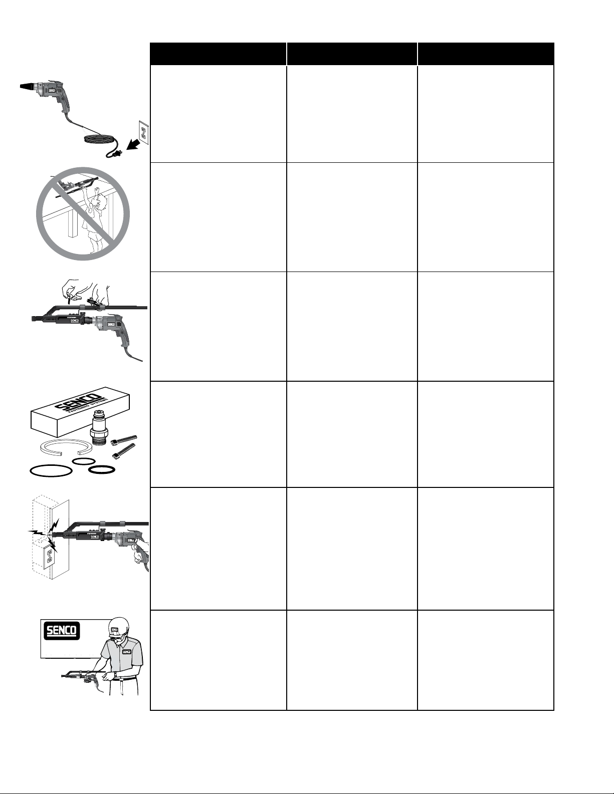
• Disconnect the plug from the
power source and/or the battery
pack from the power tool before
making any adjustments,
changing accessories, or storing
power tools. Such preventive
safety measures reduce the risk of
starting the power tool accidentally.
• Desconecte el enchufe de la
fuente de alimentación antes
de hacer ajustes, cambiar
los accesorios o guardar la
herramienta. Estas medidas
preventivas reducen el riesgo
de activar la herramienta
accidentalmente.
DE SEGURIDAD
AVERTISSEMENTS
DE SÉCURITÉ
• Débranchezlachesecteur
de la prise avant tout réglage,
changement d’accessoire ou
stockage. Cette mesure de
sécurité préventive élimine le
risque de démarrage intempestif
de l’outil.
• Store idle power tools out of
the reach of children and do not
allow persons unfamiliar with the
power tool or these instructions
to operate the power tool. Power
tools are dangerous in the hands of
untrained users.
• Maintain power tools. Check
for misalignment or binding of
moving parts, breakage of parts
and any other condition that may
affect the power tool’s operation.
If damaged, have the power
tool repaired before use. Many
accidents are caused by poorly
maintained power tools.
• Use the power tool, accessories
and tool bits etc, in accordance
with these instructions, taking
into account the working
conditions and the work to be
performed. Use of the power
tool for operations different from
those intended could result in a
hazardous situation.
• Almacene todas las
herramientas lejos del alcance
de los menores u otras
personas no capacitadas. Las
herramientas son peligrosas
en manos de los usuarios no
capacitados.
• Veriquesilaspartesmóviles
no están desalineadas o
agarrotadas, si hay piezas
rotas o si existe alguna
otra condición que pueda
afectar el funcionamiento y la
seguridad de la herramienta.
Si la herramienta está dañada,
hágala reparar antes de utilizarla.
Muchos accidentes se deben a
herramientas mal mantenidas.
• Use sólo accesorios
recomendados por el
fabricante de su modelo.
Los accesorios que resultan
apropiados para un modelo
pueden crear riesgos de lesiones
cunado se utilizan con otra
herramienta.
• Rangez les outils non utilisés
à l’abri des enfants ou autres
personnes non exercées à
leur maniement. Les outils sont
dangereux dans des mains non
expertes.
• Vériezqu’iln’yapasde
mauvais alignement ou grippage
des pièces en mouvement, ou
toute autre condition qui pourrait
affecter le bon fonctionnement
de l’outil ou compromettre la
sécurité. Si vous constatez un
dommage quelconque, faites
réparer l’outil avant de l’utiliser.
Des outils mal entretenus sont à
l’origine de beaucoup d’accidents.
• N’utilisez que des accessoires
recommandés par votre fabricant
et adaptés à votre modèle d’outil.
Des accessoire conçus pour un
type d’outil peuvent provoquer des
risques d’accident s’ils sont utilisés
sur un autre modèle.
Authorized
Service Center
• HOLD POWER TOOL BY
INSULATED GRIPPING
SURFACES when performing
an operation where the fastener
may contact hidden wiring.
Fasteners contacting a “live” wire
may make exposed metal parts of
the power tool “live” and could give
the operator an electric shock.
SERVICE
• Tool service must be performed
only by Authorized Senco repair
personnel. Service or maintenance
performed by unqualied personnel
may result in a risk of injury.
• NO TOQUE NINGUNA DE
LAS PARTES METÁLICAS DE
LA HERRAMIENTA, cuando
taladre en paredes, pisos o en
todo lugar en el que puedan
encontrarse cables elécticos
alimentados (“vivos”).
Sostenga la herramienta sólo
por las supercies aisladas a n
de impedir el choque eléctrico si
usted se encuentra con un cale
“vivo”.
SERVICIO TÉCNICO
• Las tareas de servicio técnico
de la herramienta deben
ser realizadas sólo por
personal de reparaciones de
Sencoautorizado. Las tareas
de servicio o mantenimiento
realizadas por personal no
clicado purden ocasionar
riesgos de lesiones.
• NE TOUCHEZ À AUCUNE
PARTIE MÉTALLIQUE DE
L’OUTIL si vous devez percer
dans des murs ou planchers
où peuvent se trouver des
conducteurs électriques sous
tension. Maintenez l’outil par ses
parties isolées pour prévenir tout
risque d’électrocution s’il arrive que
vous percez un conducteur sous
tension.
ENTRETIEN
• L’entretien de l’outil ne doit être
assuré que par du personnel
autorisé et qualié de Senco.
De l’entretien assuré ou des
réparations effectuées par du
personnel non qualié peuvent
occasionner des risques d’accident.
5
Page 6
TOOL USE USE DE LA HERRAMIENTA UTILISATION D L’OUTIL
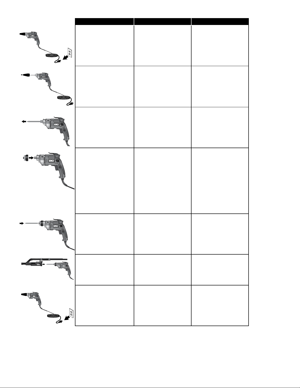
INSTALLING THE ATTACHMENT:
• Unplug tool from electrical
supply before installing
attachment.
CÓMO INSTALAR EL
ACCESORIO:
• Desconecte la herramienta
del tomacorriente antes de
instalar el accesorio.
INSTALLATION DE
L’ACCESSOIRE:
• Débranchez l’outil de la prise
de courant avant d’installer
l’accessoire.
• Remove the manufacturer’s
nose cone from the tool.
• Remove manufacturer’s bit
and holder.
• Choose the adapter which
matches the screwdriver
model and brand you are
using.
• Attach the adapter onto the
screwdriver ensuring it is fully
seated and secure.
• NOTE: If you want to use
an extension pole with the
attachment, install that, now.
See instructions for using
the extension pole on p. 8.
Otherwise, continue to next
step, below.
• Install the appropriate Senco
bit, making sure it is fully
seated (this may require some
force.)
• Quite la punta cónica de
fábrica de la herramienta.
• Quite la broca y el soporte
de fábrica.
• Elija un adaptador
compatible con el modelo y
la marca de su destornillador.
• Conecte el adaptador al
destornillador asegurándose
de que quede bien asentado
y asegurado.
NOTA: Si desea utilizar una varilla
de extensión con el accesorio,
instálela ahora. Consulte las
instrucciones sobre cómo utilizar la
varilla de extensión en la página 8.
O continúe con el siguiente paso.
• Instale la broca adecuada
de Senco, asegurándose de
que quede bien asentada
(esto puede requerir algo de
fuerza).
• Retirez de l’outil la pointe de
buse du fabricant.
• Retirez l’embout et le porteembout du fabricant.
• Choisissez l’adaptateur
approprié au modèle et à la
marque de visseuse utilisée.
• Fixez l’adaptateur à la
visseuse en veillant à ce qu’il
soit bien en place.
• NOTA: Si vous voulez
utiliser une tige de rallonge
avec l’accessoire, installezla maintenant. Voir les
instructions d’utilisation de
la tige de rallonge à la p. 8.
Autrement, passez à l’étape
suivante ci-dessous.
• Installez l’embout Senco
approprié en veillant à ce
qu’il soit bien en place (vous
aurez peut-être à exercer
une certaine force).
• Slide the attachment onto the
adapter. Make sure there’s no
gap between the attachment
and the adapter.Tighten wing
screw.
ADJUSTING FASTENER LENGTH
• Unplug tool from electrical
supply before adjusting nosepiece for fastener length.
• Deslice el accesorio en el
adaptador. Asegúrese de
que no dejar espacios entre
el accesorio y el adaptador.
Apriete el tornillo de
mariposa.
AJUSTE DEL LARGO DEL
TORNILLO
• Desenchufe la herramienta
de la fuente de alimentaciûn
elèctrica antes de ajustar la
pieza de boca al largo del
tornillo.
• Faites glisser l’accessoire
sur l’adaptateur. Assurezvous qu’il n’y a aucun
espace entre l’accessoire et
l’adaptateur. Serrez la vis à
oreilles.
RÉGLAGE DE LA LONGUEUR DE
FIXATION
• Avant díajuster líextrèmitè
rotative en fonction de la
longueur de la xation,
níoubliez pas de dèbrancher
líoutil.
6
Page 7
TOOL USE USE DE LA HERRAMIENTA UTILISATION D L’OUTIL
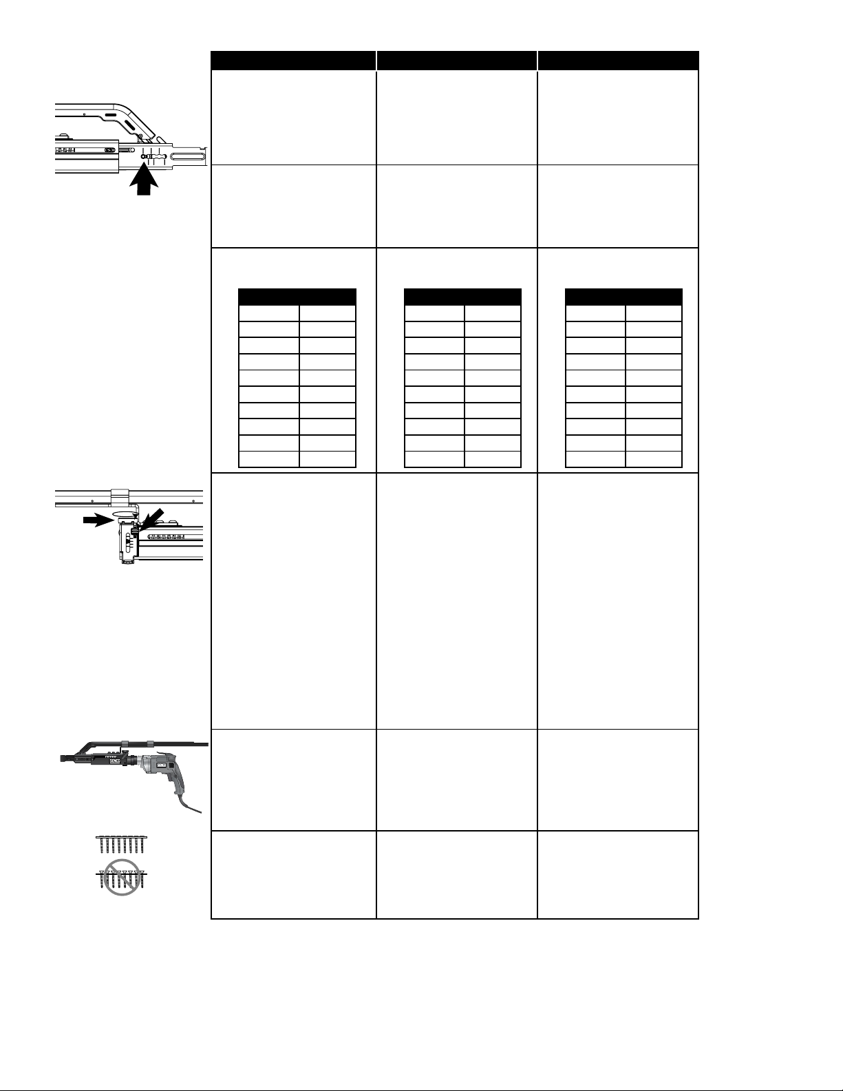
• Depress the screw selector
pin until it is ush with
nosepiece and slide the
nosepiece to the desired
setting by aligning hatch
marks with the silver
adjustment pin.
• Release pin ensuring it is
fully engaged in selected
nosepiece slot for proper
operation.
• Nosepiece has these possible
settings:
• Presione el pasador selector
de tornillos hasta que quede
al ras con la pieza cónica, y
deslice la pieza cónica hasta
el ajuste deseado alineando
las marcas sombreadas
con el pasador de ajuste
plateado.
• Suelte el pasador
asegurándose de que quede
completamente engranado
en la ranura de la pieza
cónica seleccionada a
n de lograr un correcto
funcionamiento.
• La boca puede congurarse
posiciones posibles;
• Appuyer sur le taquet du
sélecteur des vis jusqu’à ce
qu’il soit à égalité avec la
buse et glisser la buse à la
position voulue en alignant
les marques de verrouillage
sur le taquet de réglage
argenté.
• Lâcher le taquet et veiller
à ce qu’il soit entièrement
engagé dans la fente
sélectionnée de la buse an
d’assurer un fonctionnement
approprié.
• Il y a ajustements possibles
du nez;
DS220 DS320
1” 1”
1 ¼“ 1 ¼“
1 ½” 1 ½”
5/8” 1 5/8”
1
1 ¾” 1 ¾”
2” 2”
N/A 2 ¼“
N/A 2 ½”
N/A 2 ¾”
N/A 3”
ADJUSTING DEPTH OF DRIVE:
• This tool is equipped with
a locking depth-control
adjustment.
• Depress the lock switch to
release the thumbwheel
and rotate it to a notched
position. Adjust the amount
of countersink by turning the
thumbwheel clockwise to go
more shallow, or counterclockwise to go deeper.
Release the lock button after
adjustment, and make sure
the thumbwheel is locked into
a notched position.
• The attachment is now
installed and you are ready to
load in a screw strip and begin
driving screws.
DS220 DS320
25mm 25mm
32mm 32mm
38mm 38mm
41mm 41mm
44mm 44mm
51mm 51mm
N/A 57mm
N/A 64mm
N/A 70mm
N/A 76mm
CÓMO AJUSTAR LA
PROFUNDIDAD DE HINCADO:
• Esta herramienta viene
equipada con un ajuste de
control de profundidad con
bloqueo.
• Presione el interruptor de
seguridad para liberar la
ruedecilla y gírela hasta la
posición dentada. Ajuste
el avellanado girando la
ruedecilla de ajuste de
profundidad a la derecha
para una menor profundidad
o a la izquierda para una
mayor profundidad. Suelte el
botón de bloqueo después
del ajuste y asegúrese
de que la ruedecilla esté
asegurada en la posición
dentada.
• El accesorio ahora está
instalado y usted está listo
para cargar la tira de tornillos
y comenzar a atornillar.
DS220 DS320
25mm 25mm
32mm 32mm
38mm 38mm
41mm 41mm
44mm 44mm
51mm 51mm
N/A 57mm
N/A 64mm
N/A 70mm
N/A 76mm
RÉGLAGE DE LA PROFONDEUR
DE VISSAGE:
• L’outil est équipé d’un
dispositif de verrouillage de
la profondeur.
• Abaissez l’interrupteur de
blocage pour dégager la
molette, puis tournez celleci jusqu’à une position à
encoche. Réglez la noyure
en tournant la molette dans
le sens horaire pour une
faible profondeur, ou dans
le sens antihoraire pour une
grande profondeur. Relâchez
le bouton de blocage après le
réglage, et assurez-vous que
la molette est bien verrouillée
dans une position à encoche.
• L’accessoire est maintenant
installé, et vous êtes prêt à
charger une bande de vis et
à commencer le vissage.
LOADING THE TOOL
• Check to be sure the heads
of the screws are resting on
top of the plastic collation
material. This will prevent
damage to the strip guide.
CARGA DE LA HERRAMIENTA
• Asegúrese de que las
cabezas de los tornillos
descansen contra el material
plástico de intercalación. De
este modo, se evitarán daños
a la guía de la faja.
CHARGEMENT DE L’OUTIL
• Vériez que les têtes des vis
reposent bien sur le sommet
de la bande collectrice
en plastique pour éviter
d’endommager le guide.
7
Page 8

TOOL USE USE DE LA HERRAMIENTA UTILISATION D L’OUTIL
• Feed the strip into the slide
body until the 2nd empty slot
is aligned with the bit. The tool
will feed the rst screw when
depressed against the work
surface.
• Alimente la tira al interior
del cuerpo deslizante hasta
que la segunda ranura vacía
quede alineada con la broca.
La herramienta alimentará el
primer tornillo al presionarla
contra la supercie de
trabajo.
• Insérer la bande dans la
section coulissante jusqu’à
ce que la 2e fente vide soit
alignée sur l’embout. L’outil
amènera la première vis
lorsqu’il sera déclenché
contre la surface de travail.
• To remove the strip pull it
through from the bottom of the
nosepiece.
DRIVING SCREWS:
• (1) Pull the trigger to start the
motor. Engage trigger lock if
desired. (Be sure Screwgun
is operating in forward
(clockwise) direction.
• (2) Press the nosepiece, with
constant force, against the
work surface. Do not remove
the tool from the work surface
until the clutch disengages
and the bit stops rotating,
signaling a fully driven screw.
• When the screw is
countersunk to the preset depth, it automatically
disengages and makes a click
or racheting sound. This is
normal and signals completion
of the drive.
• See Adjusting Depth of Drive,
on p. 7.
• (3) Continue to allow the
motor to run.
• Release pressure against
work surface to allow the tool
to reset.
• Depress the tool against the
work surface, and the next
screw will automatically feed
into place.
CHANGING THE BIT
• Due to wear or damage, the
bit will need to be replaced
periodically or when changing
from Phillips to Square Drive
fasteners.
• (1) Loosen wing nut. (2) Remove attachment from screwgun. (3) Bit is now exposed.
(4) Remove bit (some force
required) from collar.
• Para retirar la faja, tire de
la misma desde la parte
superior de la pieza de la
boca
CÓMO ATORNILLAR:
• (1) Presione el accionador
para arrancar el motor. (Asegrese de que la herramienta
colocadora de tornillos estè
funcionando hacia adelante
(a la derecha).
• (2) Presione la pieza de la
boca, ejerciendo una fuerza
constante, contra la super-
cie de trabajo. No retire la
herramienta de la supercie
de trabajo hasta que el
embrague se desenganche y
la broca deje de girar, lo que
indica que el tornillo se ha
embutido totalmente.
• Cuando el tornillo se
embute a una profundidad
precongurada, el embrague
se desacopla automáticamente y hace un clic o un
sonido de trinquete. Esto es
normal e indica la nalización
del impulso.
• Consulte Cómo ajustar la
profundidad de hincado en la
página 7.
• (3) Continúe haciendo funcionar el motor.
• Libere la presión contra la
supercie de trabajo para
permitir que la herramienta
se restablezca.
• Presione la herramienta
contra la supercie de
trabajo y el siguiente tornillo
se colocará en su lugar
automáticamente.
CAMBIO DE LA BROCA
• La broca se deberá reemplazar periódicamente a
causa del desgaste o daños
o cuando se cambia de
tornillos Phillips a tornillos
para broca de punta
cuadrada.
• (1) Aojan la tuerca de ala.
(2) Retire el suplemento a
la her-ramienta colocadora
de tornil-los (3) Ahora
queda expuesta la broca (4)
Retire la broca del collar (se
requiere un poco de fuerza).
• Pour enlever la bande, tirezla à travers le dessus du nez
INSTALLATION DES VIS:
• (1) Appuyez sur la gâchette
pour démarrer le moteur.
(Assurez-vous que le pistolet
est placè en mode avant
(sens horaire).
• (2) Appuyez le nez sur la surface de travail avec une pression constante. N’enlevez
pas l’outil de la surface de
travail avant débrayage
et arrêt de la rotation de
la broche indiquant que
l’opération de vissage est
complètement terminée.
• Lorsque la vis arrive à la
profondeur prédéterminée,
le dispositif se débraie
automatique-ment et produit
un clic, signiant que le
vissage est terminé.
• Voir la section « Réglage de
la profondeur de vissage »
à la p. 6.
• (3) Continúe haciendo funcionar el motor.
• Relâchez la pression exercée
contre la surface de travail
pour permettre à l’outil de se
réinitialiser.
• Appuyez l’outil contre la
surface de travail, et la
prochaine vis se mettra
automatiquement en place.
CHANGEMENT DE LA BROCHE
• La broche doit être
remplacée périodiquement
en raison d’usure ou de
dommage ou de changement
entre vis à tête Phillips ou
carrées.
• (1) Se desserrent l’ecroupapil-lon. (2) Enlevez
líaccessoire installè sur le
tournevis èlec-trique. (3) La
tige de vissage devrait Ítre
visible. (4) Enlevez la tige
de vissage du collier (une
certaine force sera nècessaire).
8
Page 9

TOOL USE USE DE LA HERRAMIENTA UTILISATION D L’OUTIL
• (5) Insert new bit in screwgun
collar. (6) Guide attachment
over new bit and onto the
adapter. (7) Tighten wing nut.
CHANGING THE NOSEPIECE
• Unplug tool from electrical
supply before adjusting nosepiece for fastener length.
• 5) Inserte la nueva punta en
el cuello de la herramienta.
6) Coloque el accesorio
nuevamente en el adaptador
sobre la punta. 7) Apriete
nuevamente la tuerca
mariposa.
CAMBIO DE LA PIEZA CÓNICA
• Desenchufe la herramienta
de la fuente de alimentaciûn
elèctrica antes de ajustar la
pieza de boca al largo del
tornillo.
• (5) Insèrez une nouvelle tige
de vissage dans le collier
du tournevis èlectrique. (6)
Placez le líaccessoire sur de
nouvelles et sur l’adaptateur.
(7) Serrer l’écrou d’aile.
CHANGEMENT DE LA BUSE
• Débrancher l’outil de la prise
de courant avant de changer
la buse.
• Remove retention screw.
(a coin can be used if a
screwdriver is not available.)
• Set the nosepiece on the
longest setting possible. (see
Adjusting Fastener Length
pg. 6)
• Depress the screw selector
pin until it is completely
depressed. It will be
necessary to use a screw or
thin object to depress to this
depth.
• While holding the pin in this
position, slide the nosepiece
forward and off of the slide
body.
• Retire el tornillo de retención
(puede utilizarse una
moneda si no se dispone de
un destornillador).
• Ajuste la pieza cónica al
valormás largo posible
(consultela sección de ajuste
de lalongitud del sujetador en
la página 6).
• Presione el pasador selector
del tornillo hasta que lo haya
comprimido completamente.
Será necesario utilizar un
tornillo o un objeto delgado
para presionarlo hasta esta
profundidad.
• Al sujetar el pasador en
esta posición, deslice la
pieza cónica hacia delante y
quítela del cuerpo deslizante.
• Retirer la vis de xation
(une pièce de monnaie peut
être utilisée en l’absence de
tournevis).
• Régler la buse à la position
la plus longue (consulter les
instructions de réglage de la
longueur à la page 6).
• Appuyer sur le taquet du
sélecteur des vis jusqu’au
fond. Il faudra utiliser une
vis ou un objet mince pour
atteindre cette profondeur.
• Tout en maintenant le taquet
dans cette position, glisser la
buse vers l’avant et la retirer
de la section coulissante.
• Install the new nosepiece. • Instale la nueva pieza cónica. • Installer la nouvelle buse.
• Replace the nosepiece
retention screw ensuring it is
seated snug against the slide
body.
• Vuelva a colocar el tornillo de
retención de la pieza cónica
asegurándose de que quede
asentado rmemente contra
el cuerpo deslizante.
• Remettre en place la vis de
xation de la buse en veillant
à ce que la buse soit bien
xée à la section coulissante.
9
Page 10

TOOL USE USE DE LA HERRAMIENTA UTILISATION D L’OUTIL
INSTALLING THE EXTENSION POLE
• To Prepare the screwgun for
using the extension pole: (1)
remove the nose cone, (2)
remove bit holder assembly,
(3) attach coupler, (4) tighten
set screws. See p. 6 for
details.
• Remove the extension pole
drive shaft from inside the
extension pole, and insert it
into the tool. Push it in until
you hear it snap into place.
• Slide the extension pole shell
down onto the drive shaft.
• Thread the extension pole on
to the adapter until it’s all the
way down and tight.
(A) The handle should slide over
and down the pole. Place the collar
over the bottom of extension pole
just above the adapter. (B) Tighten
by spinning the handle clockwise
in the desired orientation. (Do not
overtighten).
• Insert the bit into the end of
the extension pole.
CÓMO INSTALAR LA VARILLA
DE EXTENSIÓN:
• Cómo preparar la pistola
atornilladora para utilizar
la varilla de extensión. (1)
retire la boquilla, (2) retire
el ensamblaje del soporte
de las brocas, (3) conecte
el acoplador, (4) apriete
los tornillos de ajuste. Para
mayor información, consulte
la página 6.
• Retire el eje de transmisión de
la varilla de extensión e insértelo
en la herramienta. Empújelo
hasta colocarlo en su posición y
escuche un chasquido.
• Deslice la estructura de
la varilla de extensión
hacia abajo en el eje de
transmisión.
• Enrosque la varilla de
extensión en el adaptador
hasta el extremo inferior y
apriete.
(A) El mango debe deslizarse
sobre y hacia abajo el polo.
Coloque el collar sobre la parte
inferior del poste de la extensión
justo por encima del adaptador. (B)
Apriete haciendo girar el mango
hacia la derecha en la orientación
deseada. (No apriete demasiado).
• Introduzca la broca en el
extremo de la varilla de
extensión.
INSTALLATION DE LA TIGE DE
RALLONGE:
• Préparation de la visseuse
pour utilisation de la tige
de rallonge : (1) Retirez la
pointe de buse; (2) retirez le
montage du porte-embout;
(3) xez le raccord; (4) serrez
les vis. Voir la p. 6 pour
obtenir des détails.
• Retirez l’arbre d’entraînement
à l’intérieur de la tige de
rallonge et insérez-le dans
l’outil. Enfoncez-le jusqu’à ce
que vous entendiez le déclic
d’enclenchement.
• Glissez la gaine de la tige
de rallonge sur l’arbre
d’entraînement.
• Vissez la tige de rallonge à
l’adaptateur jusqu’au bout et
serrez.
(A) La poignée doit glisser sur et
le long du poteau. Placer le collier
sur le bas de la barre de charge
au-dessus de l’adaptateur. (B)
Serrer en tournant la poignée dans
le sens horaire dans l’orientation
désirée. (Ne pas trop serrer).
• Insérez l’embout à l’extrémité
de la tige de rallonge.
• Slide the attachment down
over the top of the bit. Pull it
on tight, making sure there’s
no gap.
• Turn the thumb screw until it
is tight.
• Set nosepiece for the length
of screws to be driven. See
Adjusting Fastener Length,
on p. 6.
• Set depth of drive for
the desired amount of
countersink. See Adjusting
Depth of Drive on p.7 .
• Deslice el accesorio hacia
abajo sobre la parte superior
de la broca. Tire rmemente,
asegurándose de no dejar
espacios.
• Gire el tornillo de mariposa
hasta apretarlo bien.
• Ajuste la boquilla con base
en el largo de los tornillos
que utilizará. Consulte Cómo
ajustar el largo del sujetador,
en la página 6.
• Establezca la profundidad
de hincado con base en
el avellanado deseado.
Consulte Cómo ajustar la
profundidad de hincado en la
página 7.
• Glissez l’accessoire sur le
dessus de l’embout. Tirez
fermement en veillant à ce
qu’il n’y ait aucun espace.
• Tournez la poignée
secondaire jusqu’à ce qu’elle
soit bien en place.
• Réglez la buse en fonction
de la longueur des vis
utilisées. Voir la section
« Réglage en fonction de la
longueur des attaches » à
la p. 6.
• Réglez la profondeur de
vissage en fonction de
la noyure désirée. Voir la
section « Réglage de la
profondeur de vissage » à
la p. 7.
10
Page 11
TOOL USE USE DE LA HERRAMIENTA UTILISATION D L’OUTIL
• The attachment is now
installed and you are ready to
load in a screw strip and begin
driving screws.
• El accesorio ahora está
instalado y usted está listo
para cargar la tira de tornillos
y comenzar a atornillar.
• L’accessoire est maintenant
installé, et vous êtes prêt à
charger une bande de vis et
à commencer le vissage.
• Load the tool and drive screws
as described on p. 7-8
ACCESSORIES ACCESORIOS ACCESSOIRES
SENCO offers a full line of DuraSpin
screws and accessories for
your SENCO tools, including:
» Adapters (see below)
» Bits (see below)
» Extension Pole
» Storage Bag
» Assorted Nosepieces (see below)
» Safety Glasses
For more information or a complete
illustrated catalogue of Senco
accessories, contact your sales
representative or call Senco at
1-800-543-4596
• Cargue la herramienta y los
tornillos como se describe en
las páginas 7-8
SENCO ofrece una línea completa
de Accesorios para sus herramientas
SENCO, incluyendo:
» Adaptadores (ver más abajo)
» Brocas (ver más abajo)
» Varilla de extensión
» Bolsa de almacenamiento
» Piezas cónicas surtidas (ver más
abajo)
» Gafas de seguridad
Para obtener más información o
un catálogo completo ilustrado de
accesorios Senco, póngase en
contacto con su representante de
ventas o llame a Senco al 1-800543-4596.
• Chargez l’outil et enfoncez
les vis tel que décrit à la
p. 7-8
SENCO offre une gamme compléte
d’accessoires votre outil
SENCO incluant:
» Adaptateurs (voir ci-dessous)
» Broches (voir ci-dessous)
» Tige de rallonge
» Sac de rangement
» Buses assorties (voir ci-dessous)
» Lunettes de sécurité
Pour obtenir de plus amples
renseignements ou un catalogue
illustré complet des accessoires
Senco, communiquer avec votre
représentant ou appeler Senco
au 1 800 543-4596
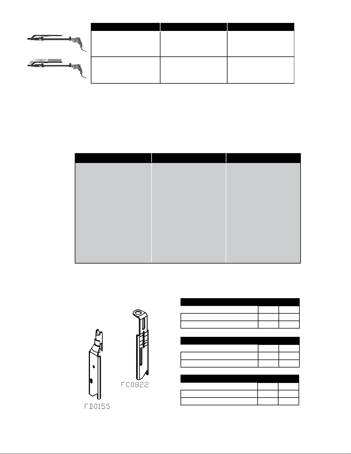
NOSE PIECES (SOLD SEPARATELY)
DS320 DS220
Metal Framing 1/2” - 2” FC0887 FC0822
Channel Fit 1/2” - 1” N/A FB0155
PIEZAS DE LA BOCA (VENDEN POR SEPARADO)
DS320 DS220
Metal encuadre 13 mm - 51 mm FC0887 FC0822
Forma de canal 13 mm - 38 mm N/A FB0155
PIÈCES DE NEZ (VENDUS SÉPARÉMENT)
DS320 DS220
Métalliques de structure 13 mm - 51 mm FC0887 FC0822
Forme de canal 13 mm - 38 mm N/A FB0155
11
Page 12

TO ATTACH TO THESE SCREW GUNS
USE THESE ADAPTERS
MB0173 Senco SG2510, SG4100
ADP015 Senco/TyRex SG2500, SG4000
ADP009 DeWalt DW252, DW253, DW255,
ADP019 Makita FS2200, FS2500, FS4200,
MB0174 Makita FS2701
ADP011 Makita 6820, 6821, 6823, 6824,
ADP020 Makita 6805BV, 6827
ADP010 Hitachi W6V4, W6VA4, W6VB3,
ADP017 Hitachi WH14DM
ADP014 Master Power MP2465, MP2461-M,
ADP018 Sioux Screwdrivers with 1/4”
UTILIZAR ESTOS
ADAPTADORES
MB0173 Senco SG2510, SG4100
ADP015 Senco/TyRex SG2500, SG4000
ADP009 DeWalt DW252, DW253, DW255,
ADP019 Makita FS2200, FS2500, FS4200,
MB0174 Makita FS2701
ADP011 Makita 6820, 6821, 6823, 6824,
ADP020 Makita 6805BV, 6827
ADP010 Hitachi W6V4, W6VA4, W6VB3,
ADP017 Hitachi WH14DM
ADP014 Master Power MP2465, MP2461-M,
ADP018 Sioux Screwdrivers with 1/4”
UTILISER CES
ADAPTATEURS
TOOL BRAND TOOL MODEL
DW257, DW266,
DW272, DW276
FS6200
6825, 6826
W6VM, W8VB2
MP2461SR-M, MP2460
Internal Hex Feature
PARA MONTAR ESTOS ATORNILLADORES
MARCA DE
HERRAMIENTAS
À JOINDRE À CES VISSEUSES
MARQUE OUTIL MODEL DE OUTIL
MODELO HERRAMIENTA
DW257, DW266,
DW272, DW276
FS6200
6825, 6826
W6VM, W8VB2
MP2461SR-M, MP2460
Internal Hex Feature
MB0173 Senco SG2510, SG4100
ADP015 Senco/TyRex SG2500, SG4000
ADP009 DeWalt DW252, DW253, DW255,
ADP019 Makita FS2200, FS2500, FS4200,
MB0174 Makita FS2701
ADP011 Makita 6820, 6821, 6823, 6824,
ADP020 Makita 6805BV, 6827
ADP010 Hitachi W6V4, W6VA4, W6VB3,
ADP017 Hitachi WH14DM
ADP014 Master Power MP2465, MP2461-M,
ADP018 Sioux Screwdrivers with 1/4”
12
DW257, DW266,
DW272, DW276
FS6200
6825, 6826
W6VM, W8VB2
MP2461SR-M, MP2460
Internal Hex Feature
Page 13

WHEN ATTACHING TO THESE SCREW GUNS: SENCO, SIOUX, OR MAKITA (WITH
THESE ADAPTERS: ADP019 & MB0174)
YOU CAN USE THESE ATTACHMENT/BIT TYPE COMBINATIONS:
ATTACHMENT BIT TYPE ITEM #
DS220 PHILLIPS EA0311
SQUARE EA0312
REX EA0313
DS320 PHILLIPS EA0314
SQUARE EA0315
REX EA0316
WHEN ATTACHING TO THESE SCREW GUNS: MASTER POWER, BLACK AND
DECKER, DEWALT, HITACHI, OR MAKITA (WITH THESE ADAPTERS: ADP011 &
ADP020)
YOU CAN USE THESE ATTACHMENT/BIT TYPE COMBINATIONS:
ATTACHMENT BIT TYPE ITEM #
DS220 PHILLIPS EA0317
SQUARE EA0318
REX EA0319
DS320 PHILLIPS EA0320
SQUARE EA0321
REX EA0322
AL CONECTAR A ESTAS ATORNILLADORES: SENCO, SIOUX, O MAKITA (CON ESTOS
ADAPTADORES: ADP019 & MB0174)
PUEDE UTILIZAR ESTAS COMBINACIONES DE TIPOS DE DE APEGO / BROCAS:
ATTACHMENT BIT TYPE ITEM #
DS220 PHILLIPS EA0311
SQUARE EA0312
REX EA0313
DS320 PHILLIPS EA0314
SQUARE EA0315
REX EA0316
AL CONECTAR A ESTAS ATORNILLADORES: MASTER POWER, BLACK AND DECKER,
DEWALT, HITACHI, O MAKITA (CON ESTOS ADAPTADORES: ADP011 & ADP020)
PUEDE UTILIZAR ESTAS COMBINACIONES DE TIPOS DE DE APEGO / BROCAS:
ATTACHMENT BIT TYPE ITEM #
DS220 PHILLIPS EA0317
SQUARE EA0318
REX EA0319
DS320 PHILLIPS EA0320
SQUARE EA0321
REX EA0322
13
Page 14

LORS DE LA FIXATION DE CES OUTILS: SENCO, SIOUX, OU MAKITA (AVEC CES
ADAPTATEURS: ADP019 & MB0174)
VOUS POUVEZ UTILISER CES COMBINAISONS DE TYPES DE FIXATION / BROCHES:
ATTACHMENT BIT TYPE ITEM #
DS220 PHILLIPS EA0311
SQUARE EA0312
REX EA0313
DS320 PHILLIPS EA0314
SQUARE EA0315
REX EA0316
LORS DE LA FIXATION DE CES OUTILS: MASTER POWER, BLACK AND DECKER,
DEWALT, HITACHI, OU MAKITA (AVEC CES ADAPTATEURS: ADP011 & ADP020)
VOUS POUVEZ UTILISER CES COMBINAISONS DE TYPES DE FIXATION / BROCHES:
ATTACHMENT BIT TYPE ITEM #
DS220 PHILLIPS EA0317
SQUARE EA0318
REX EA0319
DS320 PHILLIPS EA0320
SQUARE EA0321
REX EA0322
TECHNICAL SPECIFICATIONS
Weight 1.5 lbs 3.5 lbs
Height 3.5” 3.5”
Length 20.5” 20.5”
Width 2.75” 2.75”
Screw Range 1” - 2” 1” - 3”
Screw Diameters #6 - #10 #6 - #12
Screw Type Phillips, Square, and
DS220 DS320
REX drive.
Phillips, Square, and
REX drive.
EspEcificacionEs TEcnicas
Peso 0.68 kg 1.6 kg
Alto 89 mm 89 mm
Largo 521 mm 521 mm
Profundidad 70 mm 70 mm
Gama de tornillos (mm) 25 - 51 25 - 76
Diámetros de tornillo #6 - #10 #6 - #12
Tipo de tornillo Phillips, Square, y
spÉcificaTions TEcHniQUEs
Poids 0.68 kg 1.6 kg
Hauteur 89 mm 89 mm
Longueur 521 mm 521 mm
Largeur 70 mm 70 mm
Longueurs des xations 25 - 51 25 - 76
Diamètres de vis #6 - #10 #6 - #12
Type de vis Phillips, Square, et
DS220 DS320
REX.
DS220 DS320
REX.
Phillips, Square, y
REX.
Phillips, Square, et
REX.
14
Page 15

TROUBLESHOOTING
Problem or Symptom Probable Cause Corrective Action
• Tool will not fully drive fastener. » Bit is worn. » Replace bit.
» Power capabilities of the tool have been
exceeded.
» Tool is in reverse. » Switch tool to forward.
» Incorrect bit installed. » Ensure correct bit type and length are installed.
» Depth of drive not set properly. » See pg. 7 for proper adjustment.
• Tool does not advance fastener. » Screw length is improperly set. » See pg. 6-7 for proper adjustment.
» Return spring is weak. » Replace or return to authorized service center
» Defective collation material. » Use Senco branded fasteners for optimum
» Defective slide body. » Replace or return to Senco authorized service
» Screw strip is jammed in guide track. » Ensure strip slides free in guide track.
• Screws “kick-out” or miss-drive during use. » Screw length improperly set. » See pg. 6-7 for proper adjustment.
» Incorrect bit installed. » Ensure correct bit type and length are installed.
» Defective or damaged feed system. » Return to Senco or Authorized service center for
• Bit will not install. » Bit not properly inserted into drive shaft. » See pg. 6 for proper adjustment.
» Clutch teeth not aligned. » Pulse trigger while holding back release button.
» Not a Senco bit. » Use only the appropriate Senco bit.
• Bit slips off screw or screw is driven at an angle. » Tool slid forward during drive. » If wood nosepiece is used, replace sandpaper
» Tool is misaligned. » Return to Senco or Authorized service center for
» Bit is worn or broken. » Replace bit.
» Nosepiece is worn or damaged. » Replace or return to Senco authorized service
• Fastener jams. » Screw length improperly set. » See pg. 6-7 for proper adjustment.
» Defective collation material. » Use Senco branded fasteners for optimum
» Nosepiece damaged or bent. » Replace or return to Senco authorized service
» Screw partially driven into collation material then
feed system released.
• Slide mechanism ”sticks” or returns slowly. » Debris build-up in mechanism. » Clean mechanism.
» Weak return spring. » Replace or return to Senco authorized service
» Bit sticking in collation material. » Use Senco branded fasteners for optimum
• Tool overheats. » Drive application requires too much torque. » Discontinue use in that application.
• Pushing force becomes excessive. » Slide body is worn. » Replace or return to Senco authorized service
» CAM screw is loose or damaged. » Tighten or replace CAM screw.
» Debris build-up in mechanism. » Clean mechanism.
» Discontinue use in that application.
for repair.
performance.
center for repair.
repair.
pad.
» Hold tool rmly while driving.
repair.
center for repair.
performance.
center.
» Remove jammed screw with ngers or pliers and
resume use.
center for repair.
performance.
» Always attempt to store screws in cool dry place
before use. Overheated collation can get soft and
cause a delay in feed system return.
center for repair.
15
Page 16

IDENTIFICACIÓN DE FALLAS
Problema o Síntoma Causa Probable Acción Correctiva
• La herramienta no embute el tornillo
completamente.
• La herramienta no hace avanzar el tornillo. » El largo del tornillo se ha ajustado
• Los tornillos se salen o no engranan durante el
uso.
• No se puede instalarla broca. » La broca no está insertada correctamente en el
• La broca deja caer el tornillo o el tornillo se
embute en ángulo.
• Los tornillos se atascan. » El largo del tornillo se ha ajustado
• El mecanismo de deslizamiento se “pega” o
retorna lentamente.
• Recalentamiento de la herramienta. » La aplicación de un impulso muy arduo requiere
• Fuerza de empuje es excesiva » Deslice el cuerpo se desgasta. » Reemplace o devuelva a un centro de servicio
» La broca está gastada. » Reemplace la broca.
» Se han excedido las capacidades de potencia de
la herramienta.
» La herramienta está en reversa. » Cambie la herramienta a marcha hacia adelante.
» Se ha instalado una broca incorrecta » Asegúrese de haber instalado el tipo y longitud
» La profundidad de embutido no se ha ajustado
correctamente.
incorrectamente.
» Corona dentada gastada. » Reemplace o devuelva a un centro de servicio
» Material de intercalación defectuoso. » Utilice sujetadores marca Senco para lograr un
» Cuerpo deslizante defectuoso. » Reemplace o devuelva a un centro de servicio
» La tira de tornillos está atascada en el carril de
guía.
» El largo del tornillo se ha ajustado
incorrectamente.
» Se ha instalado una broca incorrecta. » Asegúrese de haber instalado el tipo y longitud
» Sistema de alimentación defectuoso o dañado. » Reemplace o devuelva a un centro de servicio
eje de embutido.
» Los dientes de embrague no están alineados. » Pulse el disparador al mantener sujetado el botón
» No es una broca Senco. » Utilice únicamente la broca Senco apropiada.
» La herramienta se hace deslizar hacia
abajodurante el embutido.
» La herramienta está misalinged. » Devuelva a Senco o a un centro de servicio
» La broca está desgastada o rota. » Vuelva a colocar la broca.
» La pieza cónica está desgastada o rota. » Reemplace o devuelva a un centro de servicio
incorrectamente.
» Material de intercalación defectuoso. » Utilice sujetadores marca Senco para lograr un
» La pieza de la boca está dañada o doblada. » Reemplace o devuelva a un centro de servicio
» El tornillo está parcialmente hincado en el
material de intercalación y luego se libera el
sistema de alimentación.
» Acumulación de suciedad en el mecanismo. » Limpie el mecanismo.
» Resorte de retorno débil. » Reemplace o devuelva a un centro de servicio
» La broca se atasca en el material de
intercalación.
demasiado par torsor.
» El tornillo CAM está suelto o dañado. » Apriete o reemplace el tornillo CAM.
» Los escombros se acumulan en el mecanismo. » Mecanismo limpio.
» Discontinúe el uso en dicha aplicación.
correctos de broca.
» Consulte la página 7 para conocer el ajuste
apropiado.
» Consulte la página 6-7 para conocer el ajuste
apropiado.
autorizado de Senco para su reparación.
óptimo rendimiento.
autorizado de Senco para su reparación.
» Asegúrese de que la tira se deslice libremente en
el carril de guía.
» Consulte la página 6-7 para conocer el ajuste
apropiado.
correctos de broca.
autorizado de Senco para su reparación.
» Consulte la página 6 para conocer los pasos
correctos de instalación.
de liberación.
» Si se utiliza una pieza cónica de madera,
reemplace la almohadilla de papel de lija.
» Sujete la herramienta rmemente al hincar.
autorizado para su reparación.
autorizado de Senco para su reparación.
» Consulte la página 6-7 para conocer el ajuste
apropiado.
óptimo rendimiento.
autorizado de Senco para su reparación.
» Retire el tornillo atascado con los dedos o con
pinzas, y reanude el uso.
autorizado de Senco para su reparación.
» Utilice sujetadores marca Senco para lograr un
óptimo rendimiento.
» Siempre trate de almacenar los tornillos en
un lugar fresco y seco antes de usarlos. Un
material de intercalación sobrecalentado puede
ablandarse y causar una demora en el retorno del
sistema de alimentación.
» Discontinúe el uso en dicha aplicación.
autorizado de Senco para su reparación.
16
Page 17

DÉPANNAGE
Problème ou Symptôme Cause Probable Action Correctrice
• L’outil n’insère pas complètement la xation. » La broche est usée. » Remplacez la broche.
» L’outil a été utilisé au-delà de ses capacités. » Cesser l’utilisation dans ce mode d’application.
» L’outil est en mode d’inversion. » Mettre l’outil en marche avant.
» Un embout incorrect est installé. » Veiller à ce que le type et la longueur de l’embout
» soient appropriés.
» La profondeur de l’entraînement n’est pas
correctement ajustée.
• L’outil ne fait pas pénétrer la xation. » La longueur de vis est mal réglée. » Consulter la page 6-7 pour obtenir les instructions
» La broche est usée ou encrassée. » Remplacer ou retourner à un centre de service
» Système collecteur défectueux. » Utiliser des attaches Senco pour obtenir un
» Section coulissante défectueuse. » Remplacer ou retourner à un centre de service
» La bande de vis est coincée dans le guide
d’alignement.
• Les vis tombent du système collecteur pendant
l’entraînement.
• La broche ne s’installe pas. » Broche mal installée dans l’arbre d’entraînement. » Consulter la page 6 pour obtenir les instructions
• La broche n’accroche pas la vis ou la vis part en
biais.
• Bourrage des xations. » La longueur de vis est mal réglée. » Consulter la page 6-7 pour obtenir les instructions
• Le mécanisme de coulissement « colle » ou
revient lentement.
• L’outil surchauffe. » L’application de vissage nécessite trop de
• Poussée devient excessive. » Corps coulissant est porté. » Remplacer ou retourner à un centre de service
» La longueur de vis est mal réglée. » Consulter la page 6-7 pour obtenir les instructions
» Un embout incorrect est installé. » Veiller à ce que le type et la longueur de l’embout
» Dispositif d’alimentation défectueux ou
endommagé
» Dents d’embrayage non alignées. » Actionner la détente en maintenant le bouton de
» L’embout n’est pas de marque Senco. » Utiliser uniquement un embout Senco approprié.
» L’outil ripe en avant pendant la marche. » Si une buse en bois est utilisée, remplacer le
» l’entraînement.L’outil est mal aligné. » Retourner à un centre de service Senco autorisé
» Embout usé ou brisé. » Remplacez la broche.
» Buse usée ou endommagée. » Retourner à un centre de service Senco autorisé
» Matériel défectueux collation. » Utiliser des attaches Senco pour obtenir un
» Le nez est endommagé ou tordu. » Retourner à un centre de service Senco autorisé
» Le dispositif d’alimentation est déclenché
lorsque la vis est partiellement enfoncée dans le
matériau.
» Débris dans le mécanisme. » Nettoyez le mécanisme.
» Ressort de rappel faible. » Remplacer ou retourner à un centre de service
» L’embout colle au matériau. » Utiliser des attaches Senco pour obtenir un
» force.
» Vis de verrouillage lâche ou endommagée. » Serrer ou remplacer la vis de verrouillage.
» Débris dans le mécanisme. » Nettoyez le mécanisme.
» Consulter la page 7 pour obtenir les instructions
de réglage.
de réglage
Senco autorisé pour réparation.
rendement optimal.
Senco autorisé pour réparation.
» S’assurer que la bande glisse dans le guide
d’alignement.
de réglage.
soient appropriés.
» Retourner à un centre de service Senco autorisé
pour réparation.
d’installation.
dégagement vers l’arrière.
papier abrasif.
» Tenir fermement l’outil pendant le vissage.
pour réparation.
pour réparation.
de réglage.
rendement optimal.
pour réparation.
» Retirer la vis coincée avec les doigts ou des
pinces, et poursuivre l’utilisation.
Senco autorisé pour réparation.
rendement optimal.
» Il est préférable de ranger les vis dans un endroit
frais et sec avant l’utilisation. Un surchauffage
risque d’amollir les attaches et de provoquer un
retard d’alimentation.
» Cesser l’utilisation dans ce mode d’application.
Senco autorisé pour réparation.
17
Page 18
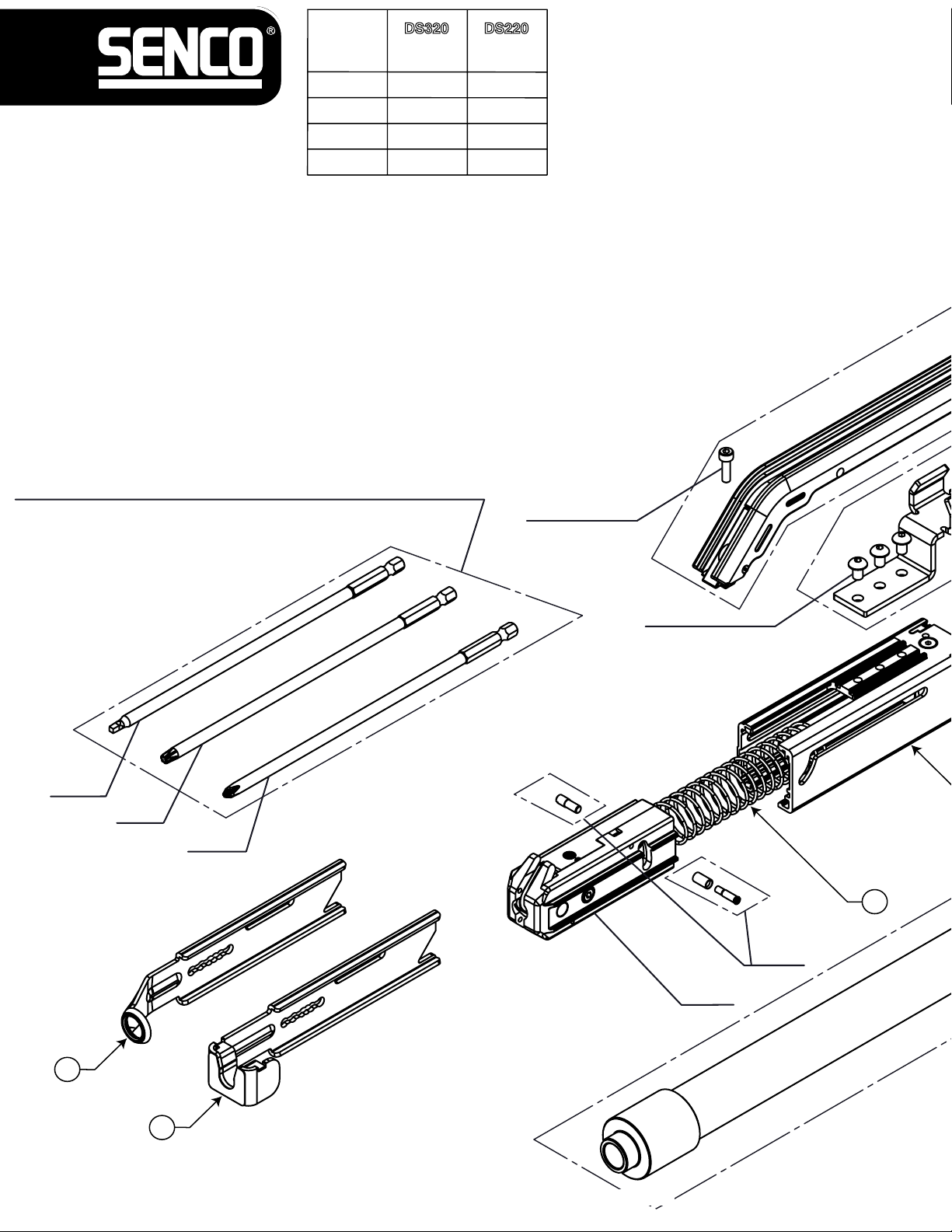
ITEM NO.
DS320
6W0003N
DS220
6W0001N
A
FC0895 FC0878
B FB0159 FB0157
C
D
ALL DRIVE BITS SOLD SEPARATELY: SEE ACCESSORIES ON PAGE 13-14
TODOS LOS BROCAS VENDEN POR SEPARADO:
VER ACCESORIOS EN LA PÁGINA 13-14
TOUS LES BROCHES VENDUS SÉPARÉMENT:
VOIR ACCESSOIRES PAGE 13-14
KB7066 KB6920
GA0721 GA0720
KD0137
SQUARE
A
M5x8mm BHCS (3x)
REX
PHILLIPS
C
FA0333
FA0322
B
METAL FRAMING AND METAL DECKING NOSE PIECES SOLD
SEPARATELY: SEE ACCESSORIES ON PAGE 11
ESTRUCTURA METAL Y CUBIERTAS METÁLICAS PIEZAS DE LA NARIZ SE VENDE POR SEPARADO: VER ACCESORIOS EN LA PÁGINA 11
CHARPENTES MÉTALLIQUES ET DES MÉTAUX PLANCHER PIÈCES DE NEZ VENDUS SÉPARÉMENT: VOIR ACCESSOIRES PAGE 11
Page 19

Screw Fastening System Attachment
GA0692
GC1437
ALL ADAPTERS SOLD SEPARATELY: SEE ACCESSORIES ON PAGE 12
TODOS LOS ADAPTADORES SE VENDEN POR SEPARADO: VER ACCESORIOS EN LA PÁGINA 12
TOUS LES ADAPTATEURS VENDUS SÉPARÉMENT: VOIR ACCESSOIRES PAGE 12
GA0687
DS220
DS320
WA0066
M4x12mm FHCS(x2)
KB7028
D
WB0054
INCLUDED WITH DS320, ONLY.
AVAILABLE AS OPTIONAL ACCESSORY FOR
DS220:
INCLUIDO CON DS320, SOLAMENTE.
DISPONIBLE COMO ACCESORIO OPCIONAL PARA DS220:
INCLUS AVEC DS320, SEULEMENT.
DISPONIBLE EN OPTION POUR DS220:
19
Page 20

Limited Warranty
SENCO® Pneumatic, DuraSpin®, Cordless Tools
& Compressors
Senco Brands, Inc. (“SENCO”) designs and constructs its products using the highest standards of material and workmanship. SENCO
warrants to the original retail purchaser that the following products will be free from defects in material or workmanship for the warranty
period specified below:
SENCO® XP Series-Red Cap SENCO PRO Series SENCO Compressors
Five years One year One year
SENCO® XP Series-Black Cap SENCO DuraSpin® SENCO Cordless Hand Nailers
Two Years One year Two years One Year
SENCO FP502 SENCO Reconditioned Products Gas Cordless
During the warranty period (which begins on the purchase date), S ENCO will repair or replace, at SENCO’s option and expense, any product or part that
is defective in materials or workmanship after examination by a S ENCO Authorized Warranty Service Center, subject to the exceptions, exclusions and
limitations descri bed below. Any replacement product or part will carry a warranty for the balance of the warranty period applicable to the replaced
product or part. A DATED SALES RECEIPT OR PROOF OF PURCHASE FROM THE ORIGI NAL RETAIL PURCHASER IS REQUIRED TO MAKE A
WARRANTY CLAIM. Product registration can be accomplished through on-line Pro duct Registration at www.senco.com or by completing and returning
the postage paid product registration form included with your Operator’s manual/p arts chart inform ation, found inside the product car ton. To make a
warranty claim, you must return the product, with proper receipt/proof of purchase and return transportation charges prepaid, t o a SENCO Authorized
Warranty Service Center. A list o f SENCO Authorized Warranty Service Centers can be found at www.senco.com
SENCO will perform its obligations under this warranty, within a reasonable time after approval of the warranty claim.
Wheelbarrow Compressors:
1. Subject to the exceptions, exclusions and limitations described below, SENCO warrants that the compressor pump will be free from defects in
2. Defective parts of the compressor pump not subject to normal wear and tear will be repaired or replaced, at SENCO's option, during the two
SENCO Cordless:
1. Subject to the exceptions, exclusions and limitations described below, SENCO warrants that the SENCO Cordless tool will be free from
2. Subject to the exceptions, exclusions and limitations described below, SENCO
The following warranty exclusions apply:
1. Normal wear parts are not covered under this warranty. Normal wear parts include, for example, isolators, drive belts, air filters, rubber o-rings,
2. This warranty does not cover parts damaged due to normal wear, misapplication, misuse, accidents, operation at other than recommended
3. Products used in production/industrial applications as defined by SENCO are excluded from this warranty.
4. Labor charges or loss or damage resulting from improper operation, maintenance or repairs are not covered by this warranty.
5. SENCO does not warrant the Wheelbarrow Compressor Engine/Motor, but the Compressor Engine/Motor may be covered under a warranty
This warranty will be honored, only if:
A. Clean, dry, regulated compressed air has been used, at air pressure not exceeding the maximum indicated on the tool casting;
B. No evidence o
C. No Deviation from operating instructions, specifications, and maintenance schedules exists (read Operator Manual for use, specifications, and
THIS WARRANTY IS THE ONLY WARRANTY ON THE PRODUCT, AND SENCO DISCLAIMS ALL OTHER WARRANTIES. ANY IMPLIED
WARRANTIES WILL BE LIMITED IN DURATION TO THE APPLICABLE WARRANTY PERIOD SPECIFIED ABOVE. SOME STATES DO NOT ALLOW
LIMITATIONS ON HOW LONG AN IMPLIED WARRANTY LASTS, SO THE ABO VE LIMITATION MAY NOT APPLY TO YOU. YOUR REMEDIES ARE
SOLELY AND E XCLUSIVELY AS STATED ABOVE. SENCO SHALL IN NO EVENT BE LIABLE FOR INCIDENTAL, CONSEQUENTIAL, INDI RECT,
OR SPECIAL DAMAGES. SOME STATES DO NOT ALLOW THE EXCLUSIO N OR LIMITATION OF INCIDENTA L OR CONSEQUENTIAL DAMA GES,
SO THE ABOVE LIMITATION OR EXCLUSION MAY NOT APPLY TO YOU. IN NO EVENT, WHETHER AS A RESULT OF A BREACH OF
CONTRACT, WARRANTY, TORT (INCLUDING NEGLIGENCE) OR OTHERWISE, SHALL SENCO’S LIABI LITY EXCEED THE PRICE OF THE
PRODUCT WHI CH HAS GIVEN RISE TO THE CLAIM O R LIABILITY. ANY LIABILITY CONNE CTED WITH THE USE OF THIS PRO DUCT SHALL
TERMINATE UPON THE EXPIRATION OF THE WARRANTY PERIOD SPECIFIED ABOVE. NO EMPLOY
ANY DISTRIBUTOR OR DEALER IS AUTHORIZED TO MAKE ANY CHANGE OR MODIFICATION TO THIS WARRANTY.
This warranty gives you specific legal rights, and you may also have other rights which vary from state to state.
SENCO will replace an y tool destroyed by an Act of God such as flood, eart hquake, hurricane or other disaster result ing only from the forces of nature.
Such a claim will be honored provided that such original retail purchaser had previously submitted a completed w arranty registration card for the tool,
and then submits proof of ownership and an acceptable statement describing such Act of God documented by an insurance carrier, police department,
or other official governmental source. To obtain instructions for filing a claim call 1-800-543-4596.
One hundred p ercent customer satisfaction is our #1 goal. If for any reason the product does not perform to the original purcha
be returned to the place of purchase within thirty days with dated sales receipt for a full refund of the purchase price.
©2006, 2009 by SENCO BRANDS, INC.
CINCINNATI, OHIO 45244-1611 USA
www.senco.com
051208
Two Years One Year Two Years
or by calling 1-800-543-4596 toll free.
materials and workmanship for two years after the purchase date.
year warranty period. If SENCO determines that repair or replacement is not feasible, SENCO will refund the purchase price less reasonable
depreciation based on actual use.
defects in materials and workmanship for two years after the purchase date.
warrants that the batteries and chargers used with SENCO
Cordless tools will be free from defects in material and workmanship for one year after the purchase date.
WARRANTY EXCLUSIONS
seals, driver blades, piston stops, piston/driver assembly, and fuel stems.
speeds or voltage (electric units only), improper storage, or damage resulting during shipping.
offered by its manufacturer.
GENERAL WARRANTY CONDITIONS
f abuse, abnormal conditions, accident, neglect, misuse or improper modifications or storage of the product; and
maintenance instructions).
EE OR REPRESENTATIVE OF SENCO OR
REPLACEMENT OF TOOL DUE TO NATURAL DISASTER
CUSTOMER SATISFACTION
ser’s satisfaction, it can
20
 Loading...