

Page 1

C-500/C-500R
PRODIGICOLOR
C-500/C-500R
Operating Manual
1
Page 2
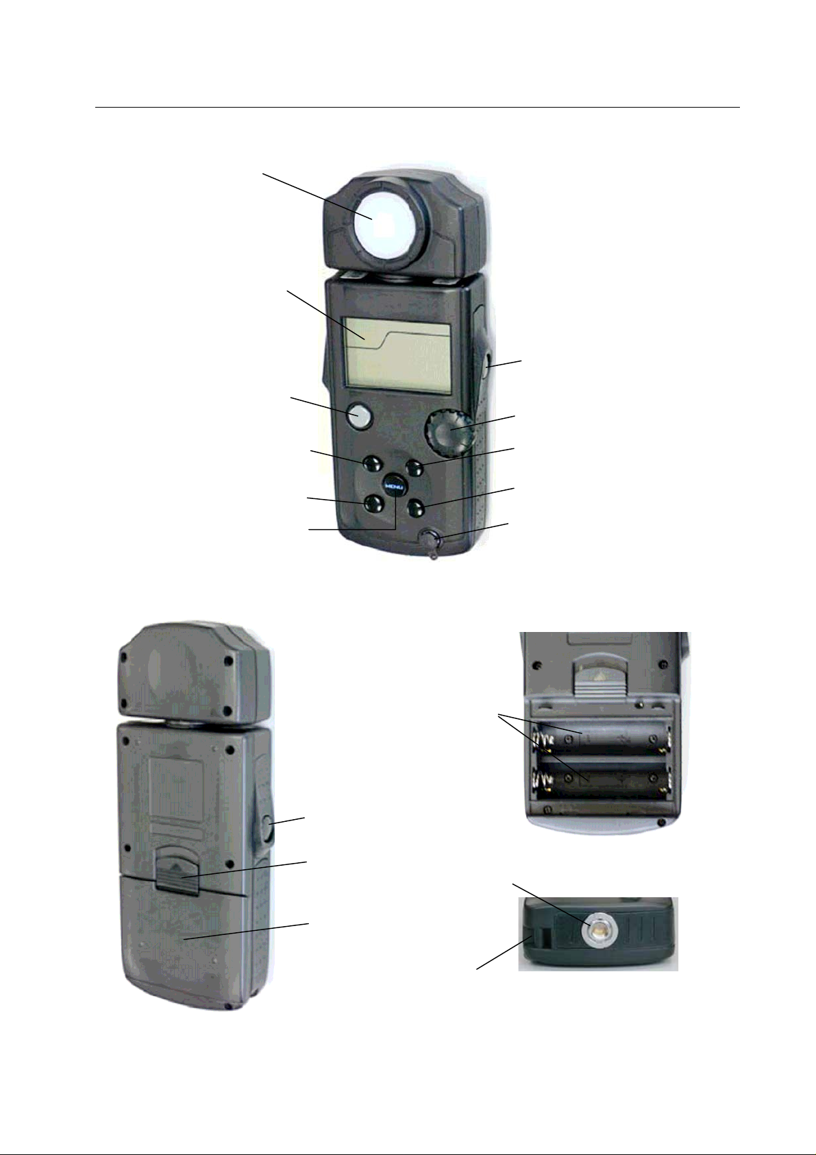
1. Parts Designation
r
Y
r
t
C-500/C-500R
(“A” in radio sub-channel setting)
⑤MODE button
(“C” in radio sub-channel setting)
①Light Senso
②Liquid Crystal Display (LCD)
③POWER button
(ON/OFF switch)
④PRESET button
⑥MENU button
⑦MEASURE/OK button
⑧Jog Wheel
⑨SET K button
(“B” in radio sub-channel setting)
⑩DISPLA
(“D” in radio sub-channel setting)
⑪Flash Synchro terminal
button
⑮Battery Compartmen
⑫⊿/BACK button
⑬Battery Cover Latch
⑭Battery Compartment Cove
⑰Strap eyelet
⑯Tripod Socket
2
Page 3

2. Explanation of the Liquid Crystal Display
C-500/C-500R
① Measuring Mode Icons
② Battery Power Indicator
③ Flash Measurement Range Icons
④ DIGITAL/FILM Mode Icons
⑤ Selected Color Temperature Display
③
⑪
⑥
⑦
Ambient
Auto-Reset Cordless Flash
Cord Flash
Wireless Flash Radio Triggering Mode
(Displayed) Battery power level is good
(Displayed) Battery power level is low. Have a spare battery ready
(Blinking) Replace battery immediately
※(Displayed)Auto-Reset Cordless Flash Mode or Cord Flash Mode
②
(Displayed) H Range Select
(Displayed) L Range Select
(Displayed) DIGITAL Mode Select
(Displayed) FILM Mode Select
(Displayed) Set-up Color temperature
①
④
⑤
C-500/C-500R
⑩
⑨
⑧
3
Page 4

C-500/C-500R
⑥ Shutter Speed Display
※(Displayed)Auto-Reset Cordless Flash Mode or Cord Flash Mode
“S” Appears when shutter speed is in full seconds
Example: 1s is displayed for shutter speed 1 second. 60 is displayed for shutter speed
1 / 60 seconds.
⑦ Preset Color / White Balance Display and Contrast Icons
(Displayed) Selected Preset Function (Selected Preset No. 1~19)
(Displayed) Used Monitoring facility
⑧ Dot Matrix Display for Preset Name, Menu and Illuminance
A menu name is displayed during menu selection.
A Preset name is displayed at the time of a Preset setup.
The unit of illumination is displayed only when Ix or FC is set up with the Illumi. Sub menu of a
custom-made setup.
⑨ LB, Measured Color Temperature and Illuminance Display
LB index, LB filter, and a color temperature are displayed by display mode.
A simple illumination display is displayed only when Ix or FC is set up with the Illumi. Sub menu of
the custom-made setup.
In the error besides the display range and the measurement range, u, Under or o, and Over are
displayed.
u, Under Appears when below display range
“u, Under” Blinks when under measured below measurement range
o, Over Appears when above display range
“o, Over” Blinks when over measured above measurement range
⑩ CC Display
CC index and CC filter are displayed by display mode.
⑪ Radio triggering channel and Quad-triggering Zone Display
(Displayed) Wireless Flash Radio Triggering Mode
The main channel which chose 1~16 channels is displayed.
The main channel (17~32) which chose 17~32 channels, and a sub-channel (A~D) are displayed.
Auto Electro-Luminescent Display (EL)
In low light (160lx or less), a green backlight will automatically illuminate the entire LCD.
The LCD will not be automatically illuminated during measuring, in Cordless Flash mode or
Wireless flash radio triggering mode.
The Electro-luminescent backlight will automatically turn off 20 seconds after last operation.
4
Page 5

C-500/C-500R
FCC & IC compliance information:
Warning: Changes or modifications to this unit not expressly approved by the party responsible
for compliance could void the user's authority to operate the equipment.
Note: This equipment has been tested and found to comply with the limits for a Class B digital device,
pursuant
To Part 15 of the FCC Rules. These limits are designed to provide reasonable protection against
harmful interference in a residential installation. This equipment generates, uses, and can
radiate radio frequency energy and, if not installed and used in accordance with the instruction, may
cause harmful interference to radio communication.
However, there is no guarantee that interference will not occur in a particular installation. If this
equipment does cause harmful interference to radio or television reception, which can be determine
by turning the equipment off and on, the user is encouraged to try to correct the interference by one
or more of the following measures:
* Reorient or relocate the receiving antenna.
* Increase the separation between the equipment and receiver.
* Consult the dealer or an experienced radio/TV technician for help.
This device complies with Part 15 of the FCC rules and also with RSS-210 of Industry Canada.
Operation is subject to the following two condition: (1) This device may not cause harmful
interference, and (2) this device must accept any interference received, including interference that
may cause undesired operation.
FCC ID Number: PFK-500-01 IC ID Number: 3916A-500001
5
 Loading...