


 Loading...
USB Dongleserver
myUTN-800
Quick Installation Guide
MHAB-QI-myUTN800
Version: 2.1 | 2018-11

Overview
This 'Quick Installation Guide' describes the hardware installation and initial setup of the myUTN-800.
Table of contents 1.
Do you need assistance? Contact us!
Monday to Thursday |
8:00 a.m. to 4:45 p.m. and |
Friday |
8:00 a.m. to 3:15 p.m. (CET) |
+49 (0)521 94226-44 |
|
support@seh.de |
|
www.seh-technology.com
Überblick
Dieser 'Quick Installation Guide' beschreibt die Hardware-Installation und Inbetriebnahme des myUTN-800.
Inhaltsverzeichnis 19.
Benötigen Sie Hilfe? Kontaktieren Sie uns!
Montag–Donnerstag |
8:00–16:45 Uhr |
Freitag |
8:00–15:15Uhr |
+49 (0)521 94226-44 |
|
support@seh.de |
|
www.seh.de |
|

Contents
General Information . . . . . . . . . . . . . . . . . . . . . . . . . . . . . . . . . . . . . . . . . . . . . . . . . . 2
Purpose ..................................................................................................................................... |
2 |
Scope of Supply ..................................................................................................................... |
2 |
Accessories............................................................................................................................... |
3 |
Technical Data......................................................................................................................... |
4 |
LED Display .............................................................................................................................. |
5 |
Display Panel ........................................................................................................................... |
5 |
Type Plate ................................................................................................................................. |
6 |
Safety Regulations . . . . . . . . . . . . . . . . . . . . . . . . . . . . . . . . . . . . . . . . . . . . . . . . . . . . 7
Hardware Installation . . . . . . . . . . . . . . . . . . . . . . . . . . . . . . . . . . . . . . . . . . . . . . . . . 8
Software Installation . . . . . . . . . . . . . . . . . . . . . . . . . . . . . . . . . . . . . . . . . . . . . . . . . . 9
Getting Started: SEH UTN Manager . . . . . . . . . . . . . . . . . . . . . . . . . . . . . . . . . . .10
Starting the SEH UTN Manager ...................................................................................... |
10 |
Assigning an IP Address to the UTN Server................................................................ |
12 |
Adding the UTN Server to the Selection List ............................................................. |
13 |
Connecting the USB Dongle to the Client.................................................................. |
14 |
Configuring the UTN Server . . . . . . . . . . . . . . . . . . . . . . . . . . . . . . . . . . . . . . . . . .15 Locking the UTN Server . . . . . . . . . . . . . . . . . . . . . . . . . . . . . . . . . . . . . . . . . . . . . .16 Mounting the UTN server in a rack . . . . . . . . . . . . . . . . . . . . . . . . . . . . . . . . . . . .17
Tools Required ...................................................................................................................... |
17 |
Prior to assembly ................................................................................................................. |
17 |
Installation ............................................................................................................................. |
18 |
Regulatory Compliance Information . . . . . . . . . . . . . . . . . . . . . . . . . . . . . . . . . .38
Quick Installation Guide |
[de] |
1 |
|
|
|

General Information
Purpose
The Dongleserver 'myUTN-800' gives network participants access to USB dongles. For this purpose, the USB dongles will be connected to the USB ports of the myUTN-800. The software tool 'SEH UTN Manager' handles the access to the USB dongles.
The SEH UTN Manager is installed on all clients that are intended to access a USB dongle in the network. The SEH UTN Manager shows the availability of all UTN servers in the network and establishes a connection between the client and the USB port including the connected USB dongle.
The lockable housing cover of the myUTN-800 allows for a central and safe storage of the USB dongles. The myUTN-800 itself can be mounted in a 19" server rack.
The administration of the myUTN-800 is done via the 'myUTN Control Center'.
Scope of Supply
Check the package content before getting started:
UTN server |
Dongleserver 'myUTN-800' |
Key |
For the lock in the dongle server lid |
Quick |
The Quick Installation Guide provides a brief |
Installation |
description of the installation of the myUTN- |
Guide |
800. |
|
(This document) |
2 power |
Power supply cable |
cords |
|
2 mounting |
65.5 mm × 43 mm × 29.8 mm |
brackets |
|
4 screws |
M4 × 4 mm |
SD card |
Inserted into SD card reader. |
2 |
[de] |
Quick Installation Guide |
|
|
|
Accessories
Value-adding accessories for your myUTN-800 are optionally available from SEH.
myUTN-800 |
The 'myUTN-800 Serviceplus package' extends the |
Serviceplus Package |
manufacturer's guarantee of your myUTN-800 |
|
from 36 to 60 months. In addition, you will receive |
|
quickly and easily an advance replacement device |
|
in case of a defect! |
|
Detailed information: |
|
http://www.seh-technology.com/services/ |
|
service-packages/myutn-800.html |
RMK3 |
For a perfect and safe storage of your myUTN-800 |
(Rack Mount Kit Type 3) |
we recommend the Rack Mount Kit 'RMK3'. |
|
Using the Rack Mount Kit, you can mount the |
|
myUTN-800 into 19" server racks. Contrary to the |
|
mounting brackets included in delivery, the RMK3 |
|
allows for a comfortable access to the myUTN-800 |
|
via telescopic slides. |
|
Detailed information: |
|
http://www.seh-technology.com/products/ |
|
rack-mount-kits.html |
Quick Installation Guide |
[de] |
3 |
|
|
|
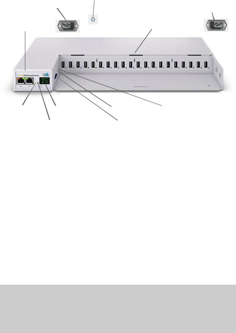
Technical Data |
|
|
|
|
|
|
|
|||||
|
|
connector for |
|
hole for strain-relief |
connector for |
|||||||
|
|
power supply 2 |
|
cord grip (RMK3) |
||||||||
|
|
|
power supply 1 |
|||||||||
|
|
(at the rear side) |
|
|
(at the rear side) |
|||||||
|
|
|
|
(at the rear side) |
||||||||
network |
|
|
|
|||||||||
|
|
USB ports 1–20 |
|
|
|
|
||||||
|
|
|
|
|
|
|||||||
connector |
|
|
|
|
|
|
|
|
||||
|
|
|
|
with LED for the USB port |
|
|
|
|||||
|
|
|
|
|
|
|
||||||
(RJ-45) |
|
|
|
|
|
|
||||||
|
|
|
|
|
|
|
|
|
||||
|
|
|
|
|
|
|
|
|
|
|
|
|
|
|
1 |
|
|
|
20 |
|
|
||||
1 |
2 |
|
|
|
|
|
|
|
|
|
|
|
|
|
|
|
|
|
|
|
|
|
|
|
|
activity LED |
display panel |
button |
restart button |
|
(yellow) |
status LED |
|
SD card |
|
|
|
|
||
|
(green) |
|
reader |
|
|
|
|
|
|
Properties |
|
Values |
|
|
Network connection |
IEEE 802.3 (1000BaseT, 100BaseTX and 10BaseT) |
|||
|
logical: |
|||
|
physical: |
2 × RJ-45 (STP, category 5 or better) |
||
Device connection |
• 20 × USB 2.0 Hi-Speed |
|
||
|
|
• 1 × SD card reader |
|
|
Current input |
|
• per connector approx. 45 mA at 100–240 VAC |
||
|
|
without load |
|
|
|
|
• per connector approx. 1.3 A at 100–240 VAC |
||
|
|
with full load on the USB ports |
||
Power consumption |
• max. approx. 6 W with full load on the USB ports |
|||
|
|
• typ. approx. 12 W with 20 USB dongles |
||
|
|
• typ. approx. 105 kWh/year |
||
Operating environment |
ambient temperature: |
5–40 °C |
||
|
|
relative humidity: |
20–80% |
|
Dimensions |
|
width: |
422 mm |
|
|
|
height: |
44 mm |
|
|
|
depth: |
155 mm |
|
|
|
(Suitable for 19" server racks.) |
||
weight: 2950 g (with housing cover, without mounting brackets)
4 |
[de] |
Quick Installation Guide |
|
|
|

LED Display
The LEDs of the UTN server provide information about its status.
LED |
Action |
Color |
Description |
Activity |
flashes at |
yellow |
Indicates the exchange of UTN data |
|
irregular |
|
packets. |
|
intervals |
|
|
Status |
permanently off |
– |
If the activity LED blinks periodically at |
|
|
|
the same time, the BIOS mode is |
|
|
|
signalized. |
|
blinks 3 times |
green |
Indicates the assignment of a Zeroconf |
|
|
|
IP address. |
|
blinks 2 times |
green |
Indicates the assignment of an IP |
|
|
|
address that does not correspond to |
|
|
|
0.0.0.0 or that comes from outside the |
|
|
|
Zeroconf range. |
USB port |
permanently off |
– |
No USB dongle is connected to the |
1–20 |
|
|
respective port. |
|
permanently on |
green |
A USB dongle is connected to the |
|
|
|
respective port. |
|
permanently on |
orange |
The connection to the respective port |
|
|
|
and the attached USB dongle is |
|
|
|
activated. |
Important:
During the activation procedure, the behavior of the
LEDs differs from this description.
Display Panel
The display panel on the front of the UTN server provides status information.
Text |
Description |
DS |
(identifier) |
|
The UTN server is operational. |
RS |
The UTN server restarts. |
DL |
Firmware/Software is being loaded onto the UTN server. Afterwards, |
|
the update is carried out. |
|
|
Quick Installation Guide |
[de] |
5 |
|
|
|

Text Description
E1 One of the two power supplies is not working.
Which connection is not working is indicated by a glowing dot (left dot = left power supply; right dot = right power supply).
E2 The SD card is formatted with an unsupported file system respectively cannot be read and be written to.
E3 The SD card is read-only.
E4 No SD card is available in the card reader.
E5 One or both network connections have no link.
Type Plate
The type plate gives important product information, such as hardware and certification information as well as the serial number. The serial number contains the production date: nnn YYYY MM nnnnn.
This information helps you e.g. during maintenance and is needed for support requests as well as for the ’myUTN-800 Serviceplus Package’ 3.
6 |
[de] |
Quick Installation Guide |
|
|
|
Safety Regulations
UTN servers are network devices for use in office environments. The myUTN-800 is designed for the integration of USB dongles into TCP/IP networks.
Important:
Before starting the installation and the initial setup procedure as well during the operation of the UTN server, note the following safety regulations. Their purpose is to protect yourself and others from personal injuries, and to avoid damage to the equipment.
•Read the documentation and make sure that your system meets the requirements listed therein.
•Avoid contact with humidity or liquids.
•The device must only be connected and operated if it is in perfect condition.
•Make sure that no-one steps on or stumbles over the cables.
•If the supplied power cords cannot be used in your country, acquire appropriate power cords that suit national provisions. For more information, consult your retailer.
•The device must be connected to sockets with safety contact.
•Position the device in a way that guarantees that the sockets for the connection of the power cords are in the proximity of the device and are easily accessible. Make sure that the device can be separated easily from the mains. Damaged power cords must be replaced immediately. For more information, consult your retailer.
•Do not connect a telephone cable to the RJ-45 connectors. The RJ-45 connectors may only be connected to SELV voltages. For the connection to the RJ-45 connectors only STP cabling (category 5 or better) may be used. The shielding must fit flushly to the connectors.
•Do not open the housing. Unauthorized modifications to the device can affect the product certification and are forbidden.
•The device must not be directly connected to outdoor lines.
•Only use a certified USB cable (< 3 m) listed at www.usb.org.
•Electrostatic discharges (ESD) may impair device performance.
•An interruption of the supply voltage may impair device performance or cause malfunctions.
Quick Installation Guide |
[de] |
7 |
|
|
|

Hardware Installation
You can directly connect up to 20 USB dongles to the myUTN-800.
clients with software tool 'SEH UTN Manager'
myUTN-800
network
USB 2.0
USB dongles
1. Connect the USB dongle to a USB port of the UTN server.
Important:
USB dongle and UTN server can be connected via a USB cable, if required.
Only use USB cables shorter than 3 meters.
2.Repeat step 1if you want to connect more than one USB dongle.)
3.Connect the network cable (RJ-45) to the UTN server.
4.Connect the power cord to the UTN server.
The UTN server boots and then is ready for use.
WARNING
Do not remove the SD card from the UTN server.
Important:
Upon delivery, the SD card is already inserted into the
SD card reader and ready for use.
Installation or formatting are not required.
8 |
[de] |
Quick Installation Guide |
|
|
|

Software Installation
The software tool ’SEH UTN Manager’ organizes the access of the USB dongles. The SEH UTN Manager is available in two versions:
•Complete version
•Minimal version (only command-line interface)
The complete version has a graphical user interface and offers additional features. A detailed description can be found in the myUTN User Manual.
The SEH UTN Manager is installed on all clients that are intended to access a USB dongle in the network. Different installation files are available, depending on the operating system.
First, you have to download the installation file for the SEH UTN Manager from the website of SEH Computertechnik GmbH:
http://www.seh-technology.com/services/downloads/ download-dongleserver/myutn-800.html
System requirements:
–Windows 7 or later except for Windows Server 20081 OS X respectively macOS 10.9 or later;
–The installation can only be carried out by users with administrative rights.
Important:
The SEH UTN Manager is also available for selected Linux systems.
All information necessary for installing and using the SEH UTN Manager in Linux environments can be found in the myUTN User Manual Linux. The documentation is available via the link given above.
1.Start the installation file.
2.Install the complete version of the SEH UTN Manager (including graphical user interface). To do so, follow the installation routine.
The SEH UTN Manager is installed on your client.
1.Windows 7 and Windows Server 2008 R2: KB3033929 (https://technet.microsoft.com/en-us/li- brary/security/3033929) must be installed.
Quick Installation Guide |
[de] |
9 |
|
|
|
Getting Started: SEH UTN Manager
After the SEH UTN Manager is started, the network will be scanned for connected UTN servers. The network range to be scanned is freely definable.
All UTN servers found will be shown in the 'network list' together with the connected USB dongles. The required UTN servers will be selected and added to the 'selection list'. The UTN servers listed in the selection list and the connected USB dongles can then be used by the user.
This chapter describes the first steps with the program.
•’Starting the SEH UTN Manager’ 10
•’Assigning an IP Address to the UTN Server’ 12
•’Adding the UTN Server to the Selection List’ 13
•’Connecting the USB Dongle to the Client’ 14
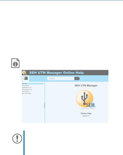
Detailed information on how to use the SEH UTN Manager can be found in the Online Help. To start the online help, go to the menu bar and select Help – Online Help.
Important:
Client and UTN server communicate via the UTN port 9200. This port must not be blocked by a security software (firewall). If necessary, you can change the port number and use a secure UTN SSL port. A detailed description can be found in the myUTN User Manual.
Starting the SEH UTN Manager
Windows
Start the SEH UTN Manager on your client via the Windows start menu. (Start All apps SEH Computertechnik GmbH SEH UTN Manager)
10 |
[de] |
Quick Installation Guide |
|
|
|
Loading...