

Sega Ghost Squad Owner's Manual
1ST PRINTING NOVEMBER ‘04
®
www.sauservice.com
Deluxe Version
Owner’s Manual
SEGA AMUSEMENTS USA, INC.
MANUAL NO. 4201-6831-01
GAME CODE: CTF
BEFORE USING THE PRODUCT, BE SURE TO READ THE FOLLOWING:
To maintain the safety:
To ensure the safe usage of the product, be sure to read the following before using the product. The
following instructions are intended for the users, operators and the personnel in charge of the opera
tion of the product. After carefully reading and sufficiently understanding the warning displays and
cautions, handle the product appropriately. Be sure to keep this manual nearby the product or elsewhere convenient for referring to it when necessary.
Herein, explanations which require special attention are enclosed with dual lines. Depending on the
potentially hazardous degrees, the terms of WARNING, CAUTION, etc. are used. Be sure to understand the contents of the displays before reading the text.
-
Indicates that mishandling the prod
uct by disregarding this warning
will cause a potentially hazardous
WARNING!
situation which can result in death
or serious injury.
-
CAUTION!
Indicates that mishandling the product
by disregarding this caution will cause
a slight hazardous situation which can
result in personal injury and or material
damage.
For the safe usage of the product, the following pictographs are used:
Indicates “HANDLE WITH CARE.” In order to protect the human body an equipment,
this display is attached to places where the Owner’s Manual and or Service Manual should
be referred to.
Perform work in accordance with the instructions herein stated.
Instructions for work are explained by paying attention to the aspect of accident prevention. Failing to
perform work as per the instructions can cause accidents. In the case where only those who have technical expertise should perform the work to avoid hazardous situation, the instructions herein state that the
serviceman should perform such work.
Be sure to turn off power before working on the machine.
To prevent electric shock, be sure to turn off power before starting the work in which the worker touches
the interior of the product. If the work is to be performed in the power-on status, the Instruction Manual
herein always states to that effect.
Be sure to ground the Earth Terminal (this, however, is not required in the case where a power cord
with earth is used).
This product is equipped with the Earth Terminal. When installing the product, Connect the Earth Ter
minal to the “accurately grounded indoor earth terminal” by using an earth wire. Unless the product is
grounded appropriately, the user can be subject to electric shock. After performing repair, etc. for the
Control equipment, ensure that the Earth Wire is firmly connected to the Control equipment.
Ensure that the Power Supply used is equipped with an Earth Leakage Breaker.
This product does not incorporate the Earth Leakage Breaker. Using a power supply which is not
equipped with the Earth Leakage Breaker can cause a fire when earth leakage occurs.
Be sure to use fuses which meet the specified rating.
Using fuses exceeding the specified rating can cause a fire and electric shock.
-
(only for the machines which use fuses).

Specification changes (removal of equipment, conversion and addition) not designated by SEGA
are not allowed.
The parts of the product include warning labels for safety, covers for personal protection, etc. It is
very hazardous to operate the product by removing parts and or modifying the circuits. Should doors,
lids and protective parts be damaged or lost, refrain from operating the product, and contact where the
product was purchased from or the office herein stated. SEGA shall not be held responsible for any
accidents, compensation for damage to a third party, resulting from the specifications not designated by
SEGA.
Ensure that the product meets the requirements of appropriate Electrical Specifications.
Before installing the product, check for Electrical Specifications. SEGA products have a nameplate on
which Electrical Specifications are described. Ensure that the product is compatible with the power
supply voltage and frequency requirements of the location. Using any Electrical Specifications different
from the designated Specifications can cause a fire and electric shock.
Install and operate the product in places where appropriate lighting is available, allowing warning
labels to be clearly read.
To ensure safety for the customers, labels and printed instructions describing potentially hazardous situation are applied to places where accidents can be caused. Ensure that where the product is operated
has sufficient lighting allowing the warnings to be read. If any label is peeled off, apply it again immediately. Please place an order with where the product was purchased from or the office herein stated.
When handling the Monitor, be very careful. (Applies only to the product w/monitor.)
Some of the monitor (TV) parts are subject to high tension voltage. Even after running off power, some
portions are still subject to high tension voltage sometimes. Monitor repair and replacement should be
performed only be those technical personnel who have knowledge of electricity and technical expertise.
Be sure to adjust the monitor (projector) properly. (Applies only to the product w/monitor.)
Do not operate the product leaving on-screen flickering or blurring as it is. Using the product with the
monitor not properly adjusted may cause dizziness or a headache to an operator, a player, or the customers.
When transporting or reselling this product, be sure to attach this manual to the product.
In the case where commercially available monitors and printers are used in this product, only the contents relating to this product are explained herein. Some commercially available equipment has functions and reactions not stated in this manual. Read this manual together with the specific Instruction
Manual of such equipment.
•
Descriptions herein contained may be subject to improvement changes without notice.
•
The contents described herein are fully prepared with due care. However, should any question arise or
errors be found, please contact SEGA.
INSPECTIONS IMMEDIATELY AFTER TRANSPORTING THE PRODUCT TO THE LOCATION.
Normally, at the time of shipment, SEGA products are in a status allowing for usage immediately after
transporting to the location. Nevertheless, an irregular situation may occur during transportation. Before
turning on power, check the following points to ensure that the product has been transported in a satisfactory status.
Are there any dented portions or defects (cuts, etc.) on the external surfaces of the cabinet?
Are Casters and Adjusters, damaged?
Do the power supply voltage and frequency requirements meet with those of the location?
Are all wiring connectors correctly and securely connected? Unless connected in the correct direction,
connector connections can not be made accurately. Do not insert connectors forcibly.
Do power cords have cuts and dents?
Do the fuses used meet specified rating? Is the Circuit Protector in an energized status?
Are all accessories available?
Can all Doors and Lids be opened with the Accessory keys? Can Doors and Lids be firmly closed?

TABLE OF CONTENTS
BEFORE USING THE PRODUCT, BE SURE TO READ THE FOLLOWING:
TABLE OF CONTENTS
INTRODUCTION OF THE OWNER’S MANUAL
1. HANDLING PRECAUTIONS ..........................................................................................
2. PRECAUTIONS CONCERNING INSTALLATION LOCATION ...................................
3. OPERATION .....................................................................................................................
4. NAME OF PARTS ............................................................................................................
5. ACCESSORIES .................................................................................................................
6. ASSEMBLY AND INSTALLATION ................................................................................
7. PRECAUTIONS WHEN MOVING THE MACHINE .....................................................
8. GAME DESCRIPTION .....................................................................................................
9. EXPLANATION OF TEST AND DATA DISPLAY .........................................................
10. CONTROL UNIT (GUN CONTROLLER) .......................................................................
11. 1C CARD UNIT .................................................................................................................
12. PROJECTOR ......................................................................................................................
13. COIN SELECTOR .............................................................................................................
14. REPLACING THE FLUORESCENT LIGHTS AND LAMPS .......................................
15. PERIODIC INSPECTION .................................................................................................
16. TROUBLESHOOTING .....................................................................................................
17. GAME BOARD .................................................................................................................
18. DESIGN RELATED PARTS ...............................................................................................
19. PARTS **MISSING** ........................................................................................................
20. WIRE COLOR CODE TABLE ...........................................................................................
21. WIRING DIAGRAMS ........................................................................................................
1 - 2
3 - 4
5 - 8
9
10 - 15
16 - 42
43 - 45
46 - 62
63 - 88
89 - 95
96 - 102
103- 112
113
114- 117
118- 119
120- 128
129- 138
139
140
XXX
SPECIFICATIONS
Installation Space : 47.2 inches width X 66.1 inches
Height : 87.8 inches
Width : 47.2 inches
Length : 58.1 inches
Weight : 557.8 lbs
Power, maximum current : 590 W 6.31 A (AC 120V 60 Hz AREA)
MONITOR : 50 Type Projection Display
INTRODUCTION OF THE OWNERS MANUAL
This Owner's Manual is intended to provide detailed descriptions together with all the
necessary information covering the general operation of electronic assemblies, electromechanicals, servicing control, spare parts, etc. as regards the product,
SEGA GHOST SQUAD DELUXE TYPE.
This manual is intended for the owners, personnel and managers in charge of operation
of the product. Operate the product after carefully reading and sufficiently understanding the instructions. If the product fails to function satisfactorily, non-technical personnel
should under no circumstances touch the internal system. Please contact where the product was purchased from.
Use of this product is unlikely to cause physical injuries or damages to property. However,
where special attention is required this is indicated by a thick line, the word "IMPORTANT"
and its sign in this manual.
Indicates that mishandling the product by disregarding this display can cause the
STOP
product's intrinsic performance not to be obtained, resulting in malfunctioning.
IMPORTANT!
SEGA AMUSEMENTS USA, INC. / CUSTOMER SERVICE
45133 Industrial Drive, Fremont, California 94538, U.S.A.
Phone : (415) 701-6580
Fax : (415) 701-6594
◆ PRODUCTION DATE ◆
This SEGA product was produced in the year of:
2004
This signifies that this work was disclosed in 2004.
DEFINITION OF LOCATION MAINTENANCE MAN AND SERVICEMAN
Non-technical personnel who do not have technical knowledge and expertise should
refrain from performing such work that this manual requires the location's main
WARNING!
Ensure that parts replacement, servicing & inspections, and troubleshooting are performed by the
location's maintenance man or the serviceman. It is instructed herein that particularly hazardous work
should be performed by the serviceman who has technical expertise and knowledge.
The location's maintenance man and serviceman are herein defined as follows:
"Location's Maintenance Man" :
Those who have experience in the maintenance of amusement equipment and vending machines, etc.,
and also participate in the servicing and control of the equipment through such routine work as equip
ment assembly and installation, servicing and inspections, replacement of units and consumables, etc.
within the Amusement Facilities and or locations under the management of the Owner and Owner's
Operators of the product.
tenance man or a serviceman to carry out, or work which is not explained in this
manual. Failing to comply with this instruction can cause a severe accident such
as electric shock.
-
-
Activities of Location's Maintenance Man :
Assembly & installation, servicing & inspections, and replacement of units & consumables as regards
amusement equipment, vending machines, etc.
Serviceman :
Those who participate in the designing, manufacturing, inspections and maintenance service of the
equipment at an amusement equipment manufacturer.
Those who have technical expertise equivalent to that of technical high school graduates as regards
electricity, electronics and or mechanical engineering, and daily take part in the servicing & control
and repair of amusement equipment.
Serviceman's Activities :
Assembly & installation and repair & adjustments of electrical, electronic and mechanical parts of
amusement equipment and vending machines.

Notes:
1. HANDLING PRECAUTIONS
When installing or inspecting the machine, be very careful of the following points and pay attention to
ensure that the player can enjoy the game safely.
Non-compliance with the following points or inappropriate handling running counter to the cautionary
matters herein stated can cause personal injury or damage to the machine.
● Before performing work, be sure to turn power off. Performing the work without
turning power off can cause an electric shock or short circuit. In the case work
WARNING!
should be performed in the status of power on, this manual always states to that effect.
● To avoid electric shock or short circuit, do not plug in or unplug quickly.
● To avoid electric shock, do not plug in or unplug with a wet hand.
● Do not expose Power Cords and Earth Wires on the surface, (floor, passage, etc.).
If exposed, the Power Cords and Earth Wires are susceptible to damage. Damaged
cords and wires can cause electric shock or short circuit.
● To avoid causing a fire or electric shock, do not put things on or damage Power
Cords.
● When or after installing the product, do not unnecessarily pull the power cord. If
damaged, the power cord can cause a fire or electric shock.
● In case the power cord is damaged, ask for replacement through where the product
was purchased from or the office herein stated. Using the cord as is damaged can
cause fire, electric shock or leakage.
● Be sure to perform grounding appropriately. Inappropriate grounding can cause an
electric shock.
● Be sure to use fuses meeting specified rating. Using fuses exceeding the specified
rating can cause a fire or electric shock.
● Completely make connector connections for IC BD and others. Insufficient insertion
can cause an electric shock.
● Specification changes, removal of equipment, conversion and/or addition, not desig-
nated by SEGA are not permitted.
• Failure to observe this may cause a fire or an electric shock. Non-compliance with
this instruction can have a bad influence upon physical conditions of the players or
the lookers-on, or result in injury during play.
• SEGA shall not be held responsible for damage, compensation for damage to a third
party, caused by specification changes not designated by SEGA.
● Be sure to perform periodic maintenance inspections herein stated.
A
www.sauservice.com
STOP
IMPORTANT!
● For the IC board circuit inspections, only the logic tester is allowed. The use of a
multiple-purpose tester is not permitted, so be careful in this regard.
● The Projector is employed for this machine. The Projector's screen is susceptible
to damage, therefore, be very careful when cleaning the screen. For details, refer to
PROJECTOR.
● Some parts are the ones designed and manufactured not specifically for this game
machine. The manufacturers may discontinue, or change the specifications of, such
general-purpose parts. If this is the case, Sega cannot repair or replace a failed game
machine whether or not a warranty period has expired.
www.sauservice.com
A
2.
PRECAUTIONS CONCERNING INSTALLATION LOCATION
This product is an indoor game machine. Do not install it outside. Even indoors, avoid
installing in places mentioned below so as not to cause a fire, electric shock, injury and
WARNING!
or malfunctioning.
● Places subject to rain or water leakage, or places subject to high humidity in the
proximity of an indoor swimming pool and or shower, etc.
● Places subject to direct sunlight, or places subject to high temperatures in the proximity of heating units, etc.
● Places filled with inflammable gas or vicinity of highly inflammable/volatile chemicals or hazardous matter.
● Dusty places.
● Sloped surfaces.
● Places subject to any type of violent impact.
● Vicinity of anti-disaster facilities such as fire exits and fire extinguishers.
● The operating (ambient) temperature range is from 5˚ to 30˚.
LIMITATIONS OF USAGE REQUIREMENTS
● Be sure to check the Electrical Specifications.
Ensure that this product is compatible with the location's power supply, voltage and
WARNING!
frequency requirements.
A plate describing Electrical Specifications is attached to the product.
Non-compliance with the Electrical Specifications can cause a fire and electric
shock.
● This product requires the Breaker and Earth Mechanisms as part of the location
facilities. Using them in a manner not independent can cause a fire and electric
shock.
● Ensure that the indoor wiring for the power supply is rated at 15 A or higher (AC
single phase 100~120 V area). Non-compliance with the Electrical Specifications
can cause a fire and electric shock.
● Be sure to independently use the power supply equipped with the Earth Leakage
Breaker. Using a power supply without the Earth Leakage Breaker can cause an
outbreak of fire when earth leakage occurs.
● Putting many loads on one electrical outlet can cause generation of heat and a fire
resulting from overload.
● When using an extension cord, ensure that the cord is rated at 15 A or higher (AC
100~120 V area). Using a cord rated lower than the specified rating can cause a fire
and electric shock.
3
www.sauservice.com
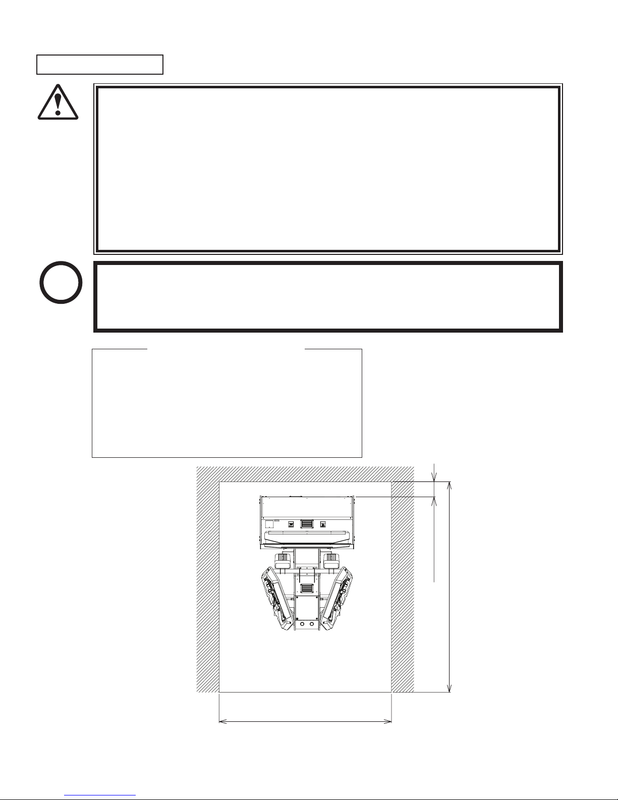
OPERATION AREA
2.8m (9.2ft)
2.3m (7.5ft)
150mm (5.9in)
● For the operation of this machine, secure a minimum area of 2.3 m (7.5 ft) (W)×2.8
WARNING!
● Be sure to provide sufficient space so as to allow this product's ventilation fan to
● SEGA shall not be held responsible for damage, compensation for damage to a third
m (9.2 ft) (D). In order to prevent injury resulting from the falling down accident
during game play, be sure to secure the minimum area for operation.
function efficiently. To avoid machine malfunctioning and a fire, do not place any
obstacles near the ventilation opening.
party, resulting from the failure to observe this instruction.
STOP
IMPORTANT!
For transporting the machine into the location's building, the minimum necessary dimensions of the opening (of doors, etc.) are 1 m (W) and
1.7 m (H).
Electric current consumption
MAX. 6.31 A (AC 120 V, 60 Hz)
MAX. 3.41 A (AC 220 V, 50 Hz)
MAX. 3.28 A (AC 220 V, 60 Hz)
MAX. 3.22 A (AC 240 V, 50 Hz)
MAX. 6.6 A (AC 110V, 60Hz; TAIWAN)
www.sauservice.com
FIG. 2
4
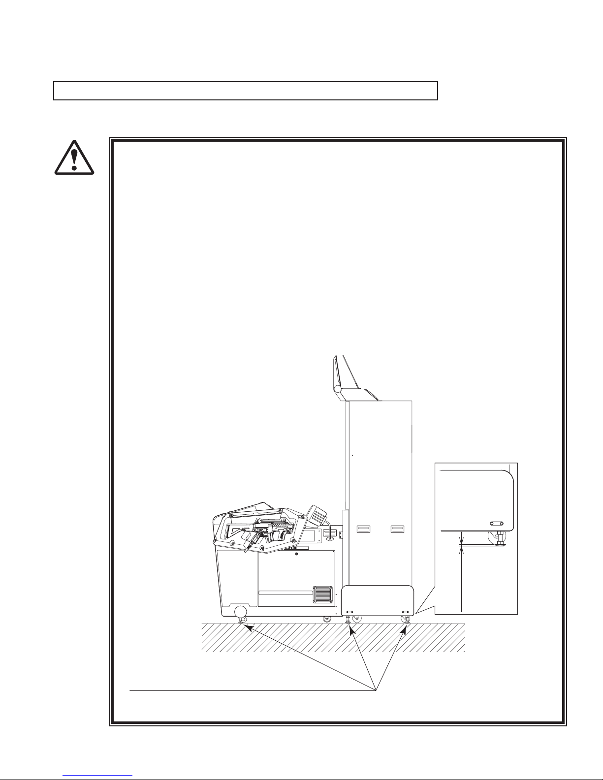
3. OPERATION
Approx. 5mm
Ensure that all of the Adjusters are in contact with the floor.
PRECAUTIONS TO BE HEEDED BEFORE STARTING THE OPERATION
To avoid injury and trouble, be sure to constantly give careful attention to the behavior and manner of the visitors and players.
In order to avoid accidents, check the following before starting the operation:
● To ensure maximum safety for the players and the customers, ensure that where the
WARNING!
product is operated has sufficient lighting to allow any warnings to be read. Opera
tion under insufficient lighting can cause bodily contact with each other, hitting ac
cident, and or trouble between customers.
● Be sure to perform appropriate adjustment of the monitor (projector). For operation of this machine, do not leave monitor's flickering or deviation as is. Failure to
observe this can have a bad influence upon the players' or the customers' physical
conditions.
● It is suggested to ensure a space allowing the players who feel sick while playing the
game to take a rest.
● Check if all of the adjusters are in contact with the surface. If they are not, the Cabinet can move and cause an accident.
-
-
FIG. 3
5
www.sauservice.com
● Do not put any heavy item on this product. Placing any heavy item on the product
WARNING!
● Do not climb on the product. Climbing on the product can cause falling down
● To avoid electric shock, check to see if door & cover parts are damaged or omitted.
● To avoid electric shock, short circuit and or parts damage, do not put the following
Flower vases, flowerpots, cups, water tanks, cosmetics, and receptacles/containers/
● To avoid injury, be sure to provide sufficient space by considering the potentially
CAUTION!
● During daily cleaning and maintenance, check the surface of the control unit
can cause a falling down accident or parts damage.
accidents. To check the top portion of the product, use a step.
items on or in the periphery of the product.
vessels containing chemicals and water.
crowded situation at the installation location. Insufficient installation space can
cause making bodily contact with each other, hitting accidents, and or trouble
between customers.
(Gun Controller) for cracks and other damage and ensure that screws are securely
fastened. Loose screws, cracks, and other damage could cause harm to players and
other customers if left unrepaired.
STOP
IMPORTANT!
Players with bare hands directly hold the controller. For operation, it is recommended
that the wet towels (paper towels) be provided.
www.sauservice.com
6
PRECAUTIONS TO BE HEEDED DURING OPERATION(PAYING ATTENTION TO CUSTOMERS)
To avoid injury and trouble, be sure to constantly give careful attention to the behavior and manner of the visitors and players.
● To avoid injury and accidents, those who fall under the following categories are not
allowed to play the game.
WARNING!
• Those who need assistance such as the use of an apparatus when walking.
• Those who have high blood pressure or a heart problem.
• Those who have experienced muscle convulsion or loss of consciousness when playing
video game, etc.
• Those who have a trouble in the neck and or spinal cord.
• Intoxicated persons.
• Pregnant women or those who are in the likelihood of pregnancy.
• Persons susceptible to motion sickness.
• Persons whose act runs counter to the product's warning displays.
● A player who has never been adversely affected by light stimulus might experience
dizziness or headache depending on his physical condition when playing the game.
Especially, small children can be subject to those conditions. Caution guardians of
small children to keep watch on their children during play.
● Instruct those who feel sick during play to have a medical examination.
● To avoid injury resulting from falling down and electric shock due to spilled drinks,
instruct the player not to place heavy items or drinks on the product.
● To avoid electric shock and short circuit, do not allow customers to put hands and
fingers or extraneous matter in the openings of the product or small openings in or
around the doors.
● To avoid falling down and injury resulting from falling down, immediately stop the
customer's leaning against or climbing on the product, etc.
● To avoid electric shock and short circuit, do not allow the customers to unplug the
power plug without a justifiable reason.
● Immediately stop such violent acts as hitting and kicking the product. Such violent
acts can cause parts damage or falling down, resulting in injury due to fragments and
CAUTION!
falling down.
● Playing close to the cabinet could cause the Gun Controller to strike the cabinet,
possibly causing an accident. Be sure to ask your customers to maintain a safe
distance during play.
● Wearing large rings and other accessories during play could result in injury to
players' fingers. Be sure to ask your customers to remove such accessories before
playing.
7
www.sauservice.com

STOP
IMPORTANT!
● The Gun Controller for use on 1P side (left side) and 2P side (right side) are
different. Ensure that players do not confuse the right and left side guns when
starting play.
● Make sure to avoid disturbing customers when moving/removing the machine from
its current location.
www.sauservice.com
8
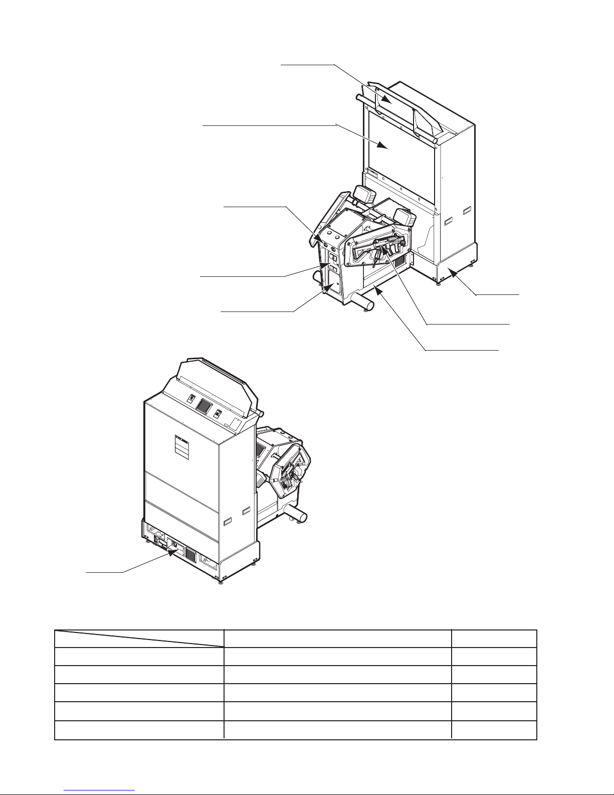
4. NAME OF PARTS
PTV .
50 TYPE PROJECTION DISPLAY
COIN CHUTE DOOR
BILLBOARD
IC CARD UNIT
PTV BASE
CASHBOX DOOR
GUN CONTROLLER
MAIN CABLINET
AC UNIT
TABLE 4
Width × Depth × Height Weight
PTV 88.19 in × 21.9 in × 65.7 in 220.4 lb
PTV BASE 47.2 in × 24.4 in × 12.2 in 57.3 lb
BILLBOARD 46.06 in × 16.14 in × 15.16 in 39.68 lb
MAIN CABINET 44.9 in × 42.91 in × 39.76 in 216.05 lb
When assembled 47.24 in × 66.14 in × 67.8 in 557.77 lb
FIG. 4
9
www.sauservice.com
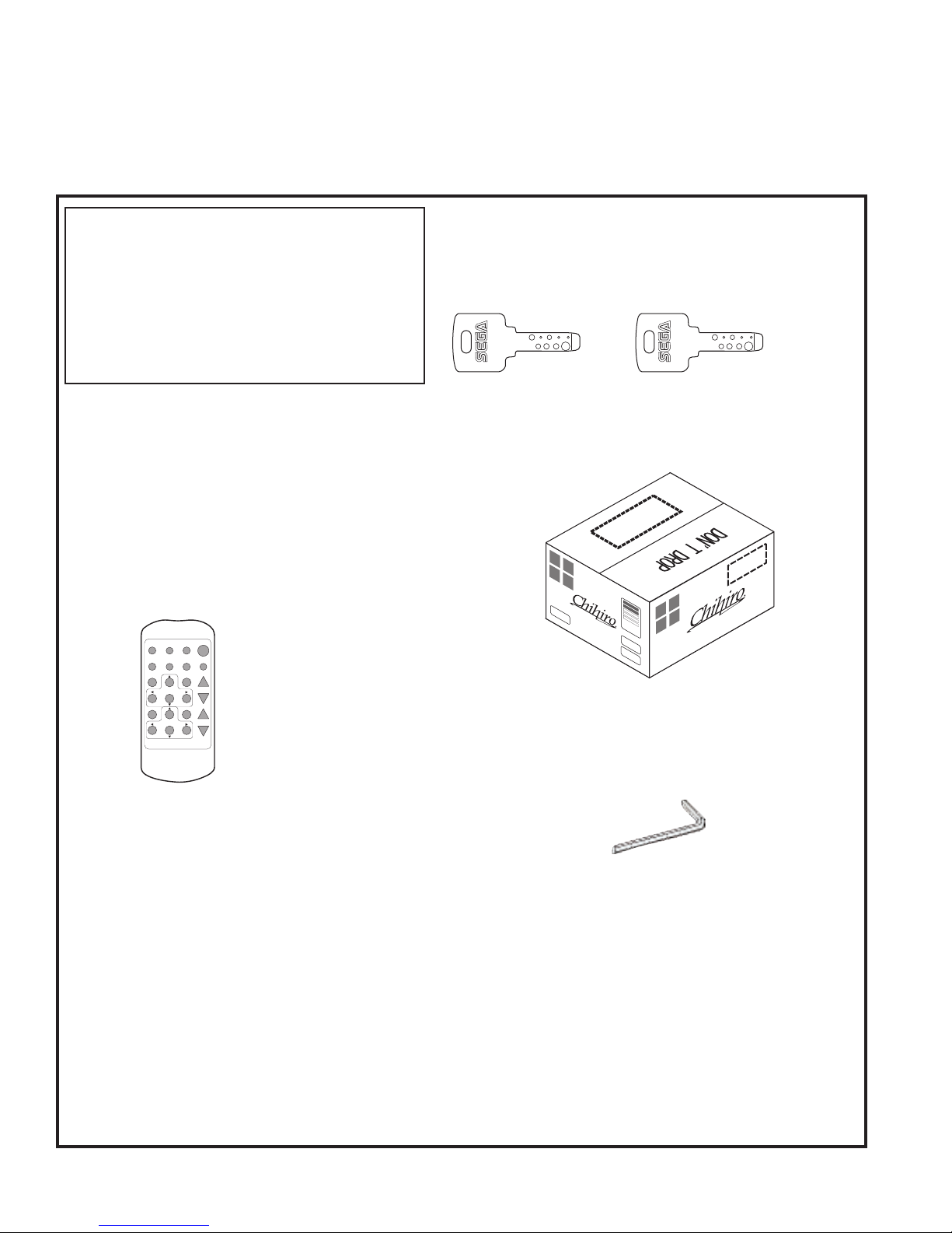
5. ACCESSORIES
TEST MODE WRITING
POSITION
ADJUST
SELECT
RESET
R BG
PIC-ADJ
SET
P
When transporting the machine, make sure that the following parts are supplied.
TABLE 5 a ACCESSORIES
DESCRIPTION OWNERS MANUAL
Part No.(Qty.)
4201-6831-01
Note
Figures
NOTE: Parts not labeled with part numbers are as yet
unregistered or cannot be registered. Be sure to handle
all parts with care, as some parts are not available for
purchase separately.
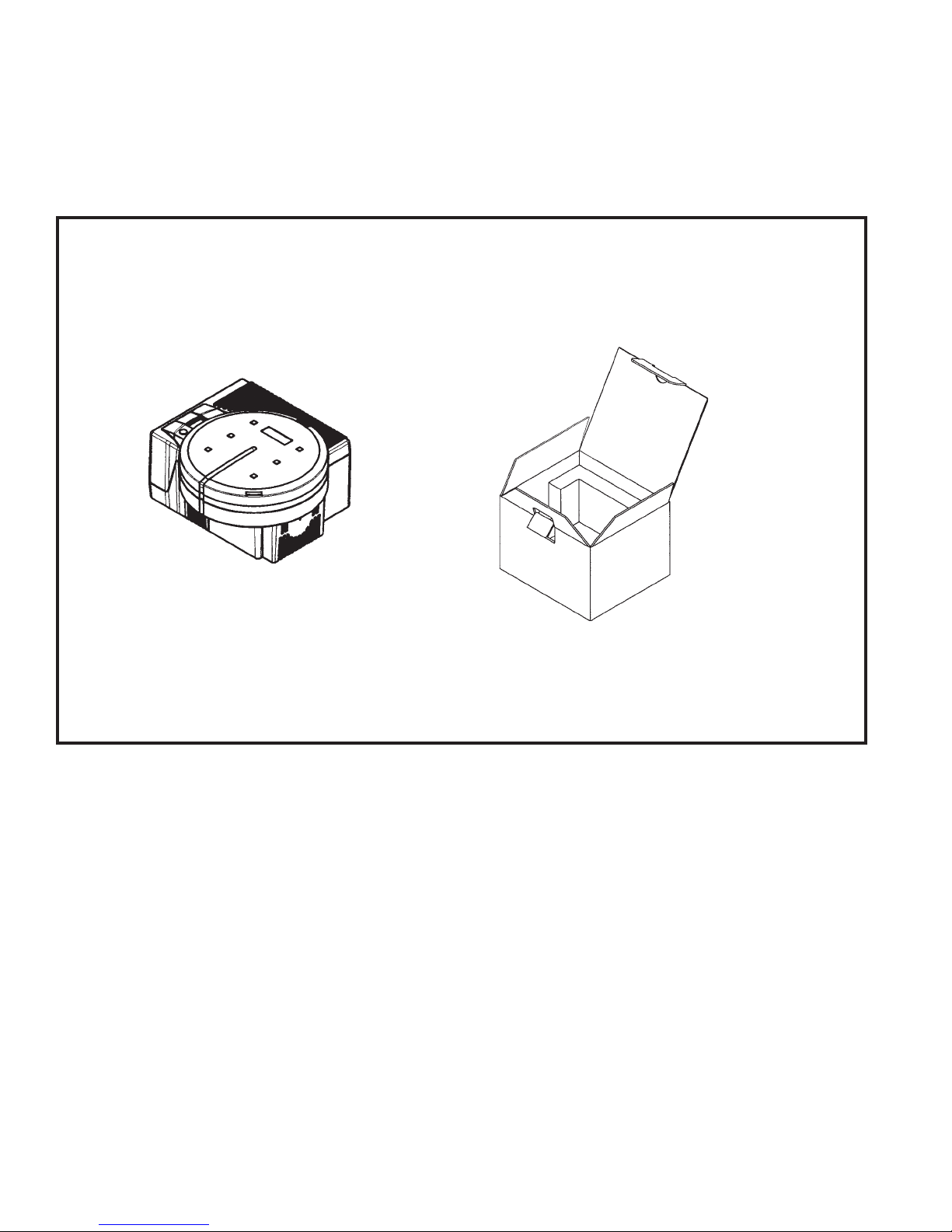
CARTON BOX
601-11219-01 (1)
TOSHIBA
200-5536 (1)
Remote Controller used for
adjustment of the projector.
See Section 12.
Used for transporting the
Game Board.
See FIG. 5 a.
KEY MASTER
220-5576 (2)
For opening/closing
the doors
KEY
(2)
For the CASHBOX DOOR
The Keys are inside the Coin
Chute Door at the time of shipment from the factory.
L-WRENCH
540-0043-91 (1)
The Remote Controller is attached to
the Projector at the time of shipment.
www.sauservice.com
10
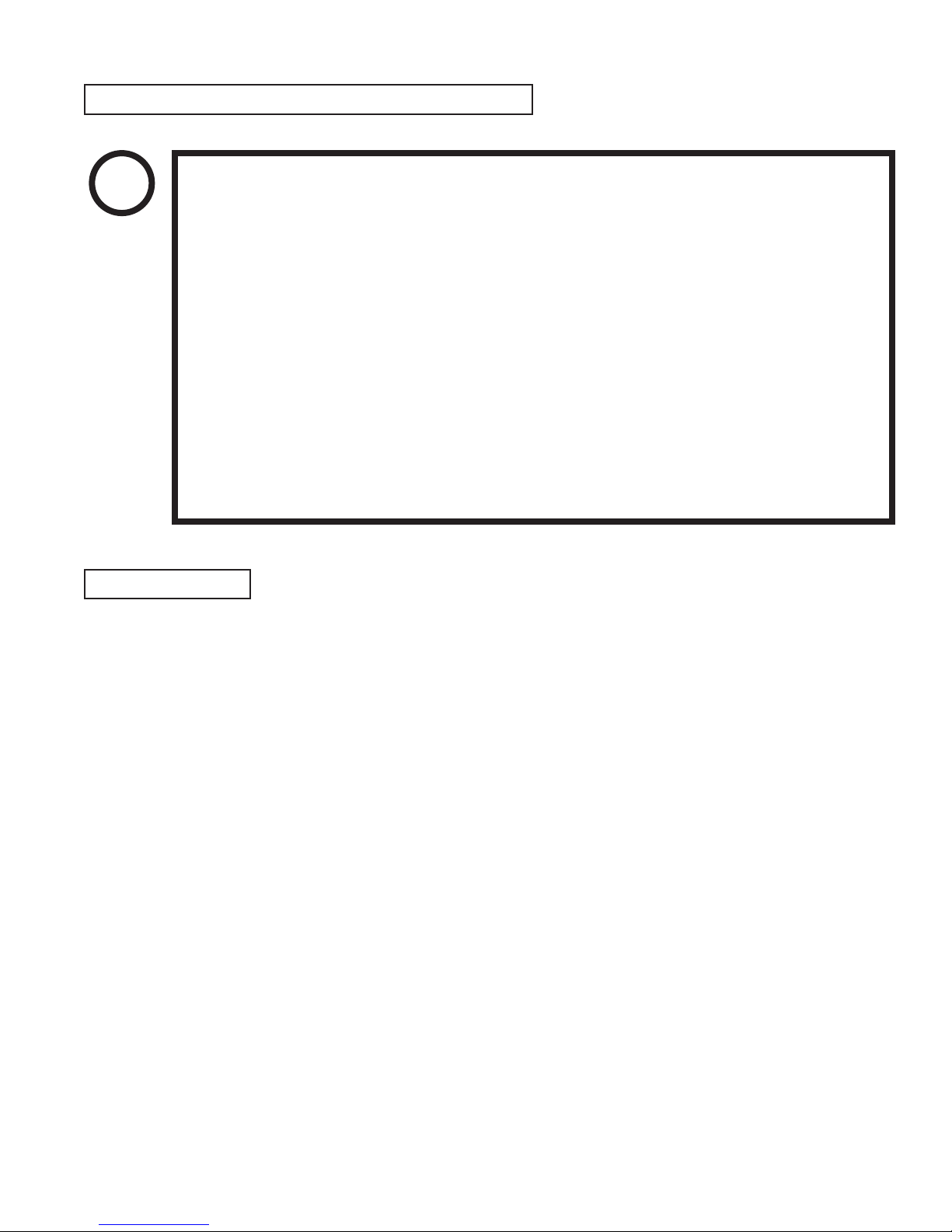
HOW TO USE THE CHIHIRO BOARD CARTON BOX
STOP
IMPORTANT!
INSTRUCTIONS
● Wrap the Chihiro Board in a plastic bag.
Replacement or repair of the Game Board (Chihiro) for this product should be undertaken at the appropriate repair center. Be sure to follow the specifications below when
requesting repairs/sending the board to the repair center. Not following the specifications
may result in the board not being accepted or in extra charges being made.
● Put the game board in the carton box as is. Do not carry out any disassembly or part
removal other than that specified.
● Follow the procedure and instructions regarding direction below when placing the
Game Board in the carton box.
● When packing the game board with the Media Board attached, do not remove the
Key Chip.
● When packing the game board with the Media Board detached, be sure to include
the AVIP Cable.
● When packing, attach the accessory stickers in the specified places on the Game
Board and carton box.
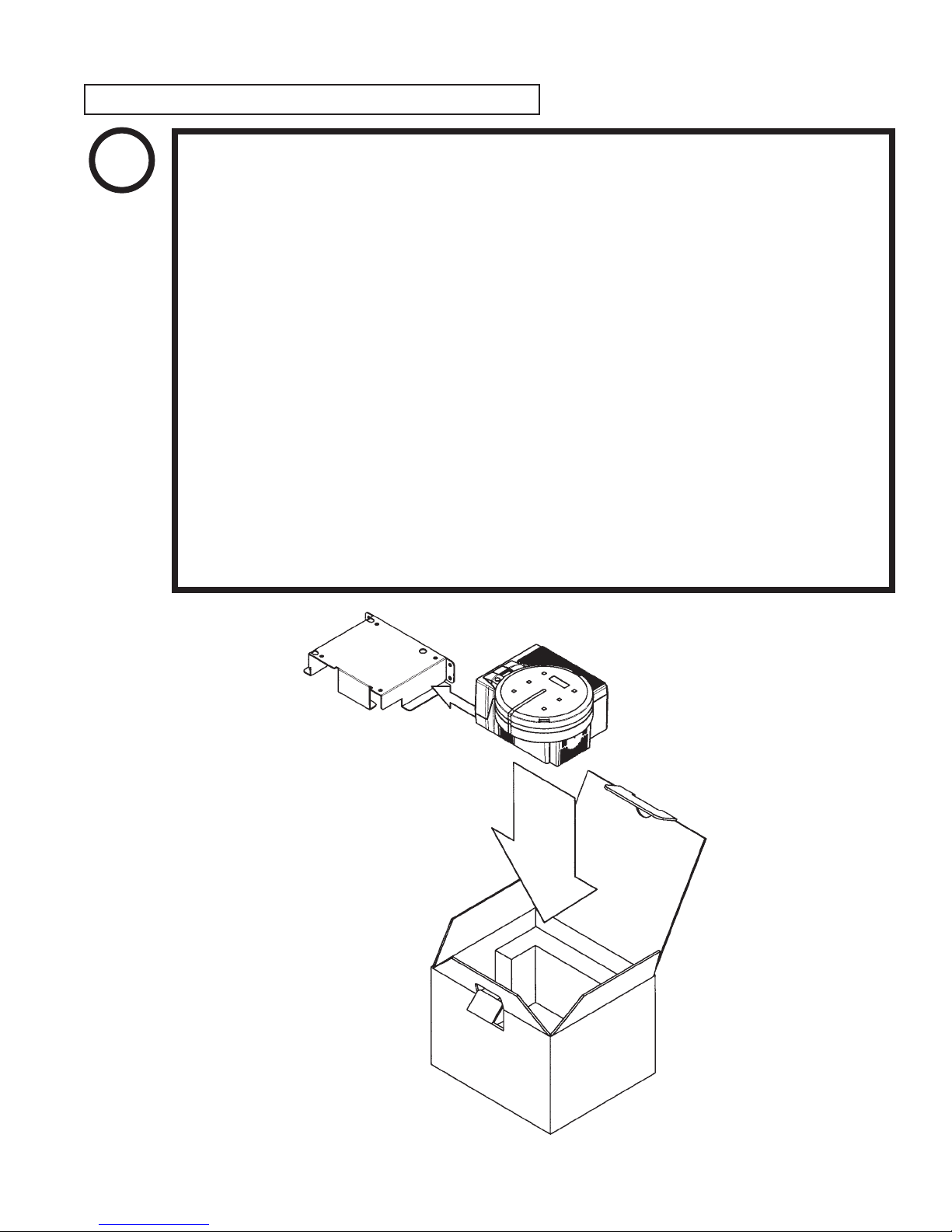
● Place it on top of the bottom surface cushioning material. Turn the Filter Board to face the side with the
three honeycomb buffers. Placing it in the opposite direction may cause damage to the Filter Board.
● Insert corrugated cardboard into the space between the lateral honeycomb buffers of the bottom surface
cushioning material and stow the AVIP cable inside.
● Place the Chihiro Board wrapped in the bottom surface cushioning material into the carton box. Use the
handles on the bottom surface cushioning material.
● Place the upper surface cushioning material on top of the Chihiro Board. Be sure to align it in the right
direction, as it will not fit otherwise.
● Close the top of the carton box and seal it tightly with adhesive tape.
11
www.sauservice.com
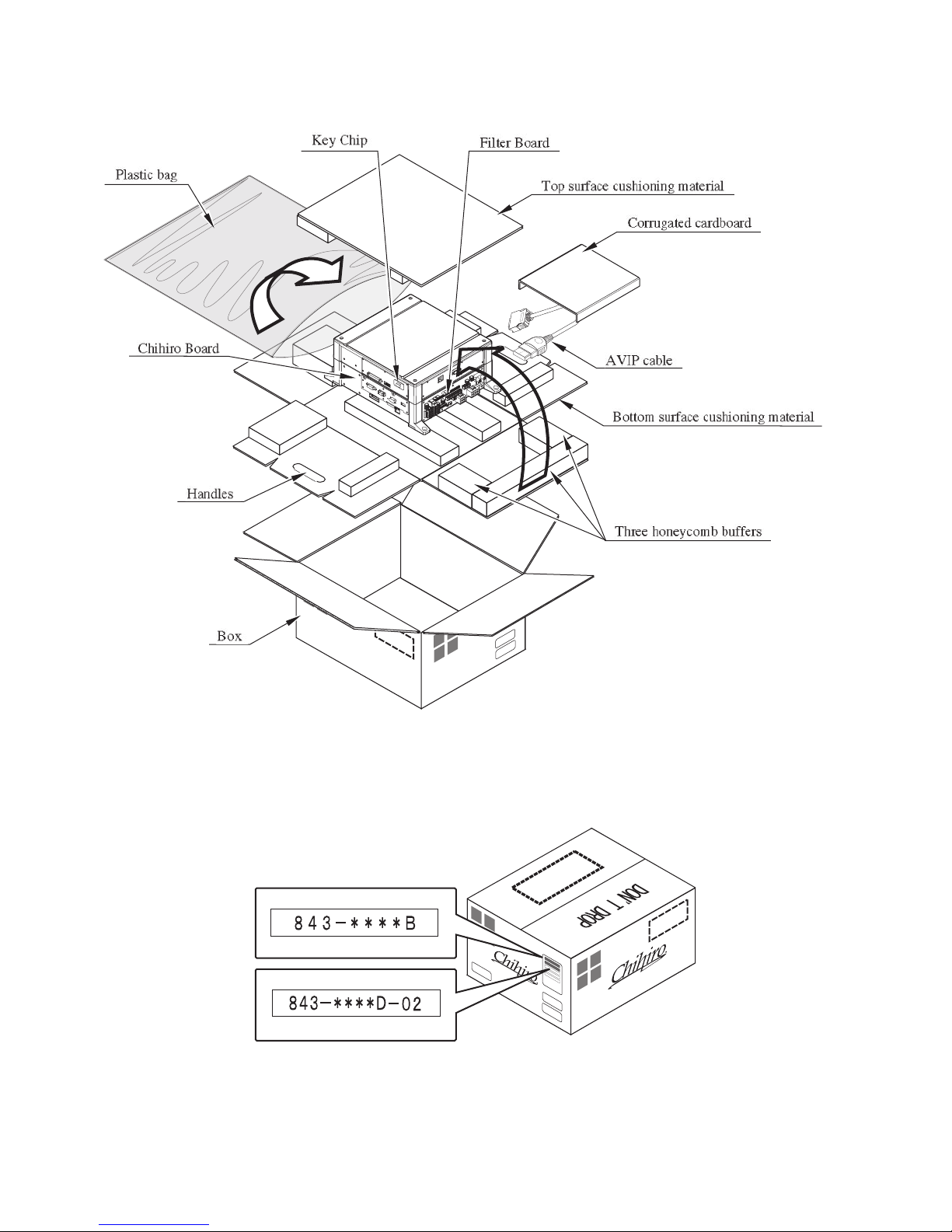
FIG. 5 a
FIG. 5 b
www.sauservice.com
12
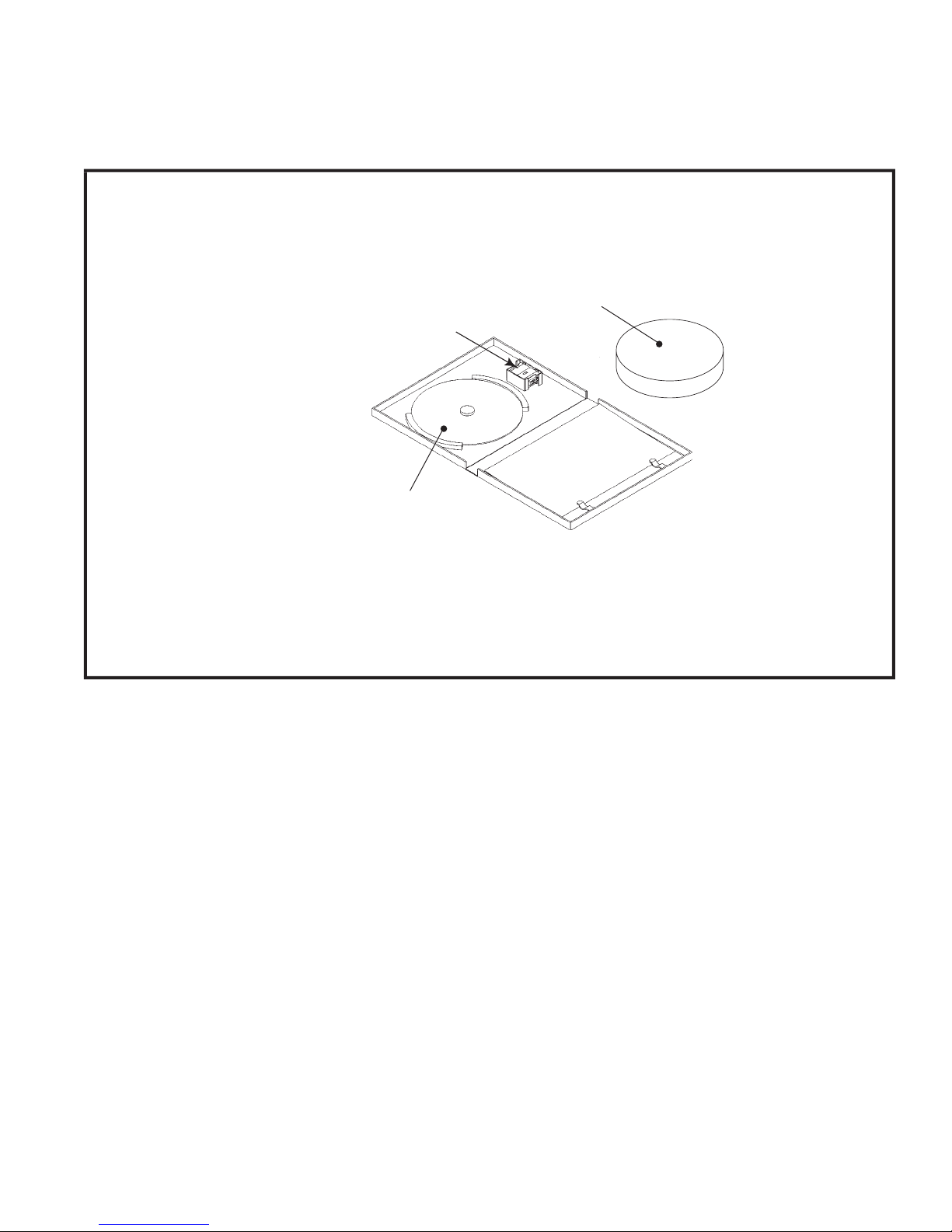
TABLE 5 b
The following Table 5b lists the parts that had been separately packed when the product was shipped
from the factory but are necessary when you use the product. These parts will be mounted on the product
when installing and assembling it.
GD SOFT KIT CTF
CUSHION SPONGE
601-11137 (1)
GD-ROM Disc Protector
KEY CHIP (1)
See 6 of Section 6.
GD SOFT CTF
See 6 of Section 6.
NOTE: When you order the GD-ROM disc only, specify the part
number 610-0652-0012 (GD SOFT CTF).
13
www.sauservice.com
The following Table 5c lists the parts that are separately marketed but are necessary when
booting this product's software. When having unpacked the shipping crate, make sure that all the
parts in this Table 5c are in the crate. If not so, contact where you have obtained the product.
TABLE 5 c (XKT-0833 : GD-ROM DRIVE KIT)
GD-ROM DRIVE
610-0617
610-0617-01
123
(1)
Device that loads the software in a GD-ROM disc.
See 6 of Section 6.
GD-ROM DRIVE CARTON BOX
(1)
Used for transporting the GD-ROM DRIVE.
See FIG. 5 d.
This carton box is a standard accessory of
the GD-ROM drive. If you want to obtain the
carton box itself separately, specify the part
number 601-11031.
www.sauservice.com
14
HOW TO USE THE CARTON BOX (GD-ROM DRIVE)
STOP
IMPORTANT!
When you want to order for replacing or repairing service of the GD-ROM drive that
is used by the product, pack it in a carton box as instructed below, and then deliver the
carton box to a service agent. If you do not observe the instruction, your order may
not be accepted or may be charged additionally. If you handle the GD-ROM drive
differently from the following instructions, its components may be damaged.
● Contain the GD-ROM drive in a dedicated carton box. Do not disassemble it or
remove any part from it unless otherwise instructed.
● Before containing the GD-ROM drive in a dedicated carton box, attach the GDROM drive lid (DISC LID) onto the drive and fix the lid with a screw.
● Before containing the GD-ROM drive in a dedicated carton box, remove the GDROM disc from the drive. Do not attempt to move the GD-ROM drive with a GDROM disc inside.
● Before containing the GD-ROM drive in a dedicated carton box, remove the GDROM drive bracket. Carefully keep the GD-ROM drive bracket and the 4 set
screws, because they will be reused.
● When inserting the GD-ROM drive into a dedicated carton box, be careful about an
inserting direction as illustrated below.
● The packing materials in a carton box are used as a cushion. Use them always when
inserting the GD-ROM drive into a dedicated carton box. Do not bend them.
Remove the GD drive bracket.
FIG. 5 c
15
www.sauservice.com
6. ASSEMBLY AND INSTALLATION
● Perform assembly work by following the procedure herein stated. Failing to comply
with the instructions can cause electric shock hazard.
WARNING!
● Perform assembling as per this manual. Since this is a complex machine, erroneous
assembling can cause an electric shock, machine damage and or not functioning as
per specified performance.
● When assembling, be sure to use plural persons. Depending on the assembly work,
there are some cases in which working by one person alone can cause personal
injury or parts damage.
● Ensure that connectors are accurately connected. Incomplete connections can cause
electric shock hazard.
● Be careful not to damage the wires. Damaged wires may cause electric shock or
short circuit or present a fire risk.
● Do not carelessly push the PTV. Pushing the PTV carelessly can cause the PTV to
fall down.
● This work should be performed by the site maintenance individual or other skilled
professional. Performing work by non-technical personnel can cause a severe
accident such as electric shock. Failing to comply with this instruction can cause a
severe accident such as electric shock to the player during operation.
● Provide sufficient space so that assembling can be performed. Performing work in
places with narrow space or low ceiling may cause an accident and assembly work
to be difficult.
● To perform work safely and avoid serious accident such as the cabinet's falling
down, do not perform work in places where step-like grade differences, a ditch, or
slope exist.
● Do not use this product with connectors other than those that were connected and
used with the Game Board at the time of shipping. Do not carelessly connect wires
to connectors that were not used at the time of shipping, as this may cause overheating, smoke or fire damage.
● When handling plastic parts, use care. Do not give a shock or apply excessive load
to the fluorescent lamps and plastic parts. Failure to observe this can cause parts
CAUTION!
www.sauservice.com
damage, resulting in injury due to fragments, cracks and broken pieces.
● To perform work safely and securely, be sure to prepare a step which is in a secure
and stable condition. Performing work without using the step can cause violent
falling down accidents.
● Make sure that the GD cable connector is inserted parallel to the plug. Improper
insertion may cause damage to the connector and present a fire risk.
16
When carrying out the assembling and installation, follow the following 9-item sequence.
ASSEMBLING THE BILLBOARD
1
2
ASSEMBLING THE PTV
3
ASSEMBLING THE CABINET
4
SECURING IN PLACE(ADJUSTER TUNING)
5
ATTACHING THE FLUORESCENT LIGHTS AND LAMPS
6
INSTALLING THE GD-ROM DRIVE(SETTING THE GD-ROM DISC)
POWER SUPPLY AND EARTH CONNECTION
7
8
TURNING THE POWER ON
ASSEMBLY CHECK
9
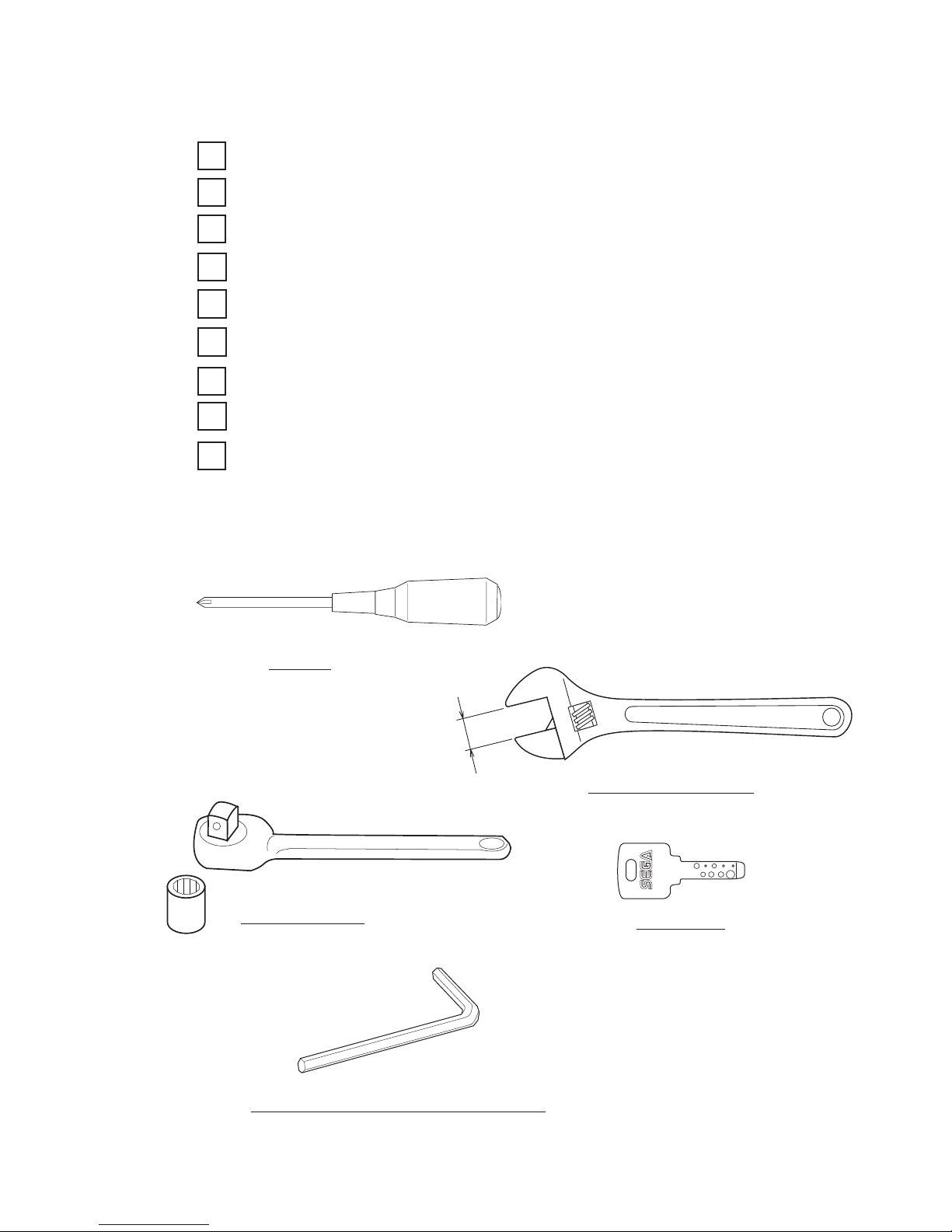
The master key (accessories) in addition to the tools such as a Phillips type screwdriver, wrench, socket
wrench and Ratchet Handle are required for the assembly work.
Phillips type screwdriver
(for screw)
SOCKET WRENCH, (for hexagon bolt)
RATCHET HANDLE
WRENCH (for hexagon bolt)
KEY MASTER
L-WRENCH (3mm L-shaped hex wrench, included)
17
www.sauservice.com
1
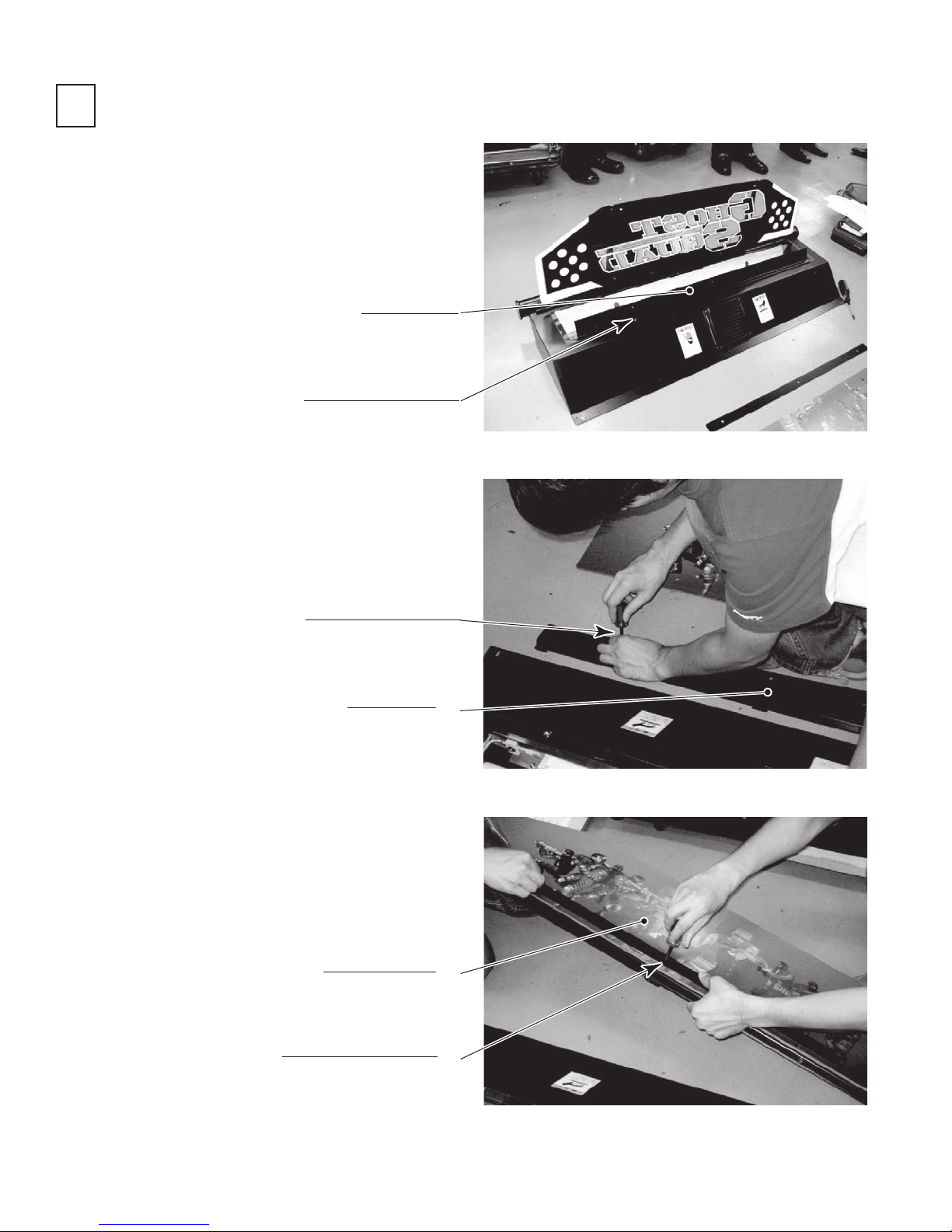
ASSEMBLING THE BILLBOARD
● Undo the 2 truss screws, and remove the
pop bracket.
POP BRACKET
TRUSS SCREW (2), black
M4×8
PHOTO 6. 1 a
● Undo the 3 truss screws, and remove the
pop holder.
TRUSS SCREW (3), black
M4×8
POP HOLDER
● Attach the billboard pop by fitting it be-
tween the pop bracket and pop holder, and
fixing it in place with the 3 truss screws.
BILLBOARD POP
TRUSS SCREW (3), black
M4×8
PHOTO 6. 1 b
www.sauservice.com
PHOTO 6. 1 c
18
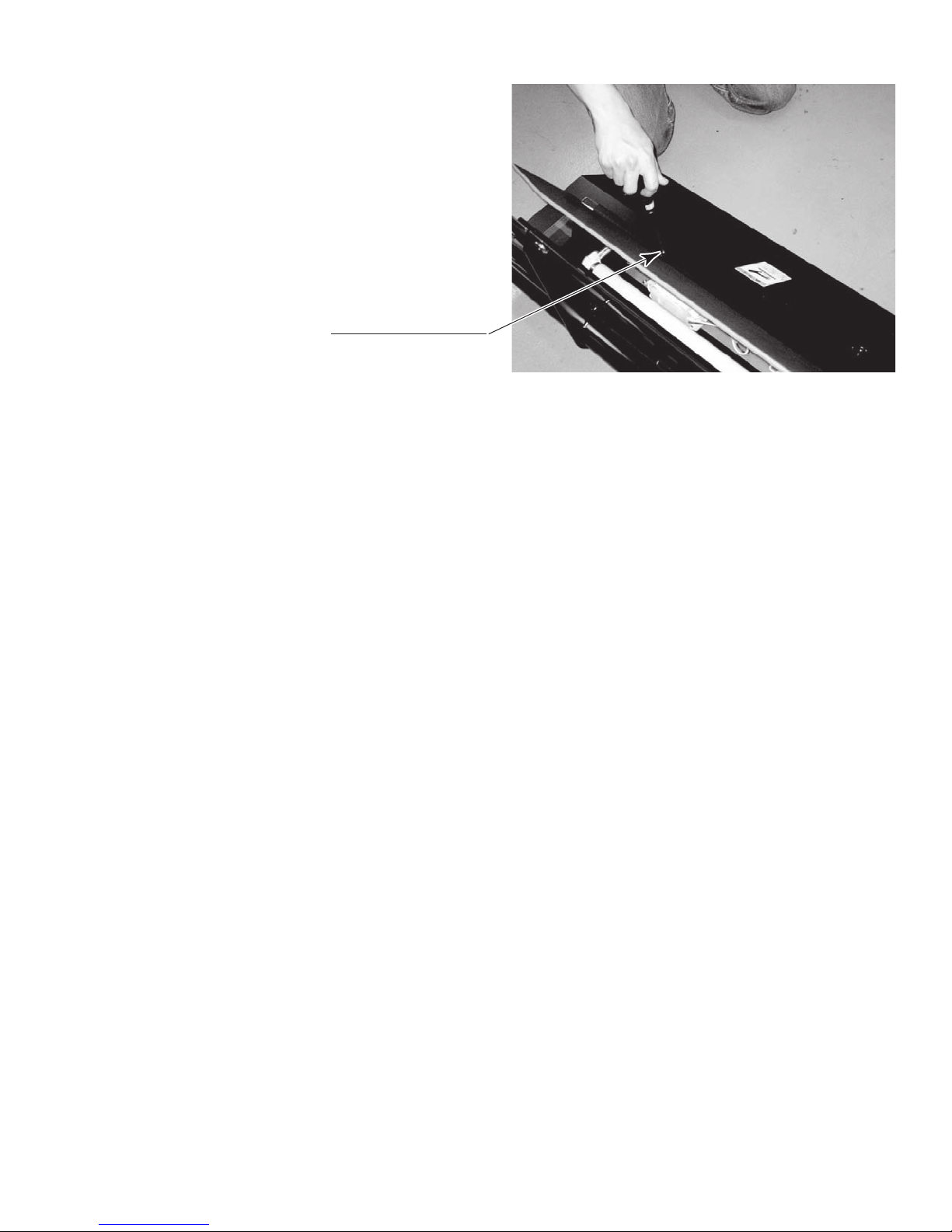
● Attach the assembled billboard pop using
the 2 truss screws.
TRUSS SCREW (2), black
M4×8
PHOTO 6. 1 d
19
www.sauservice.com
2
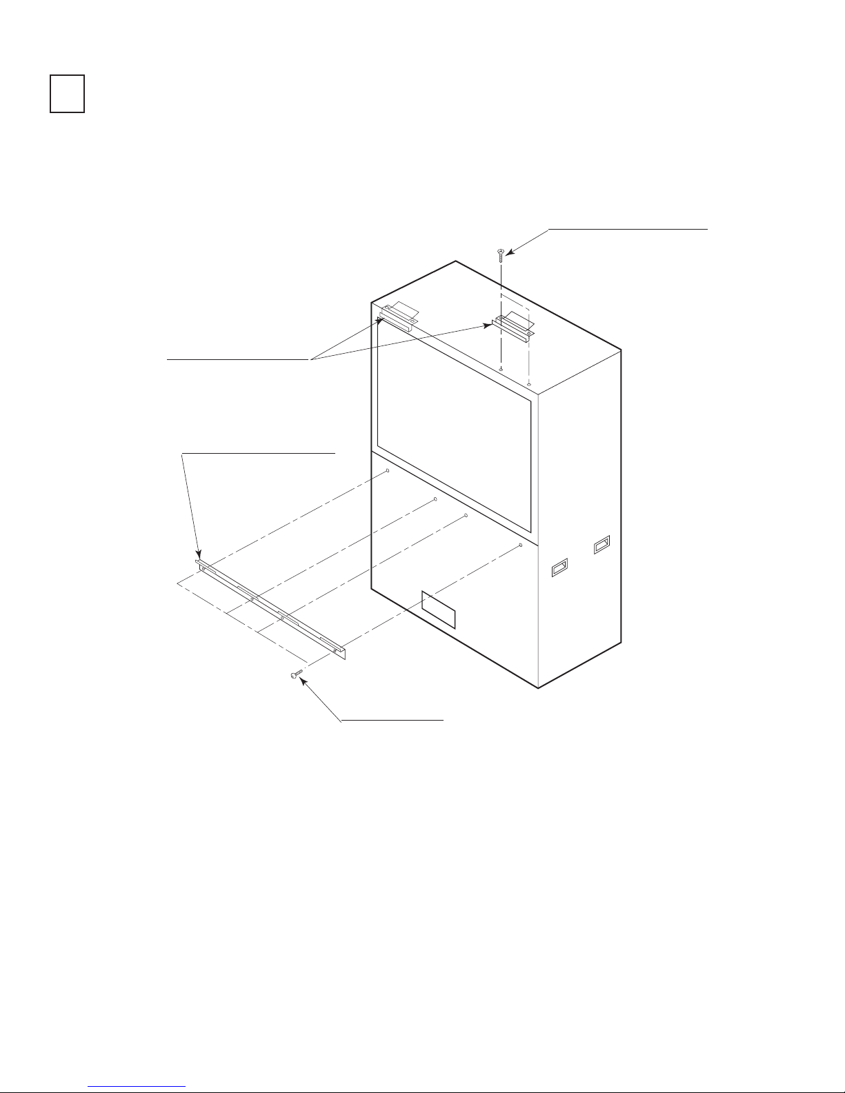
ASSEMBLING THE PTV
● By using 2 Flat Head screws, secure the 2 Mask Bracket Uppers to the PTV ceiling.
● Secure the Mask Bracket Lower to the front of PTV with 4 screws.
FLAT HEAD SCREW (2 each)
M4×8
MASK BRACKET UPPER
MASK BRACKET LOWER
www.sauservice.com
SCREW (4), black
M5×16, w/flat & spring washers
FIG. 6. 2 a
20
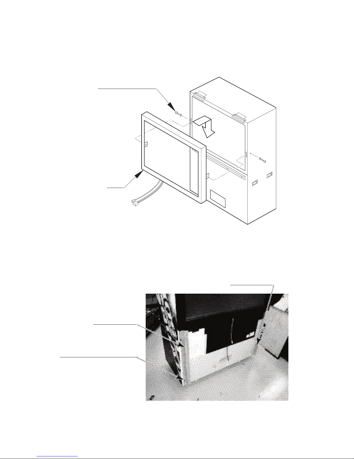
● Install Mask to the PTV front. Install the Mask in a manner hooking up to both 2 Mask
Bracket Uppers and the Mask Bracket Lower. Simultaneously insert the projections of
the Mask into the square holes in the PTV screen left and right.
● Secure the Mask by fastening a screw for each from both sides of PTV.
TRUSS SCREW (2), black
M5×25, flat washer used
MASK
FIG. 6. 2 b
● Affix the side bracket L and side bracket R to the PTV front face using 2 screws each. Be careful of the
orientation of the parts.
SIDE BRACKET L
SIDE BRACKET R
SCREW (2 ea), black
M5×16, w/flat & spring washers
21
PHOTO 6. 2 a
www.sauservice.com
3
ASSEMBLING THE CABINET
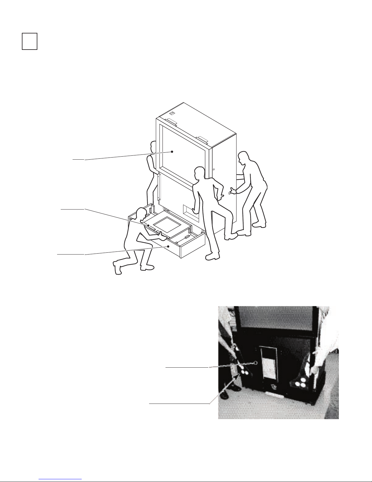
● Move the PTV to the back of the PTV base.
● Put the PTV on the PTV base. To do this, you will need at least 4 people to lift the PTV, and another per-
son to hold the PTV base to stop it from moving. Lower the PTV until it touches the supports. Take care
not to damage any wiring during this step.
PTV
SUPPORT
PTV BASE
FIG. 6. 3 a
● Attach the front panel using 4 truss screws. Take care
that you do not damage any wiring during this step.
FRONT PANEL
TRUSS SCREW (4), black
M5×20, flat washer used
You will need at least 5 people to
perform this step.
www.sauservice.com
PHOTO 6. 3 a
22
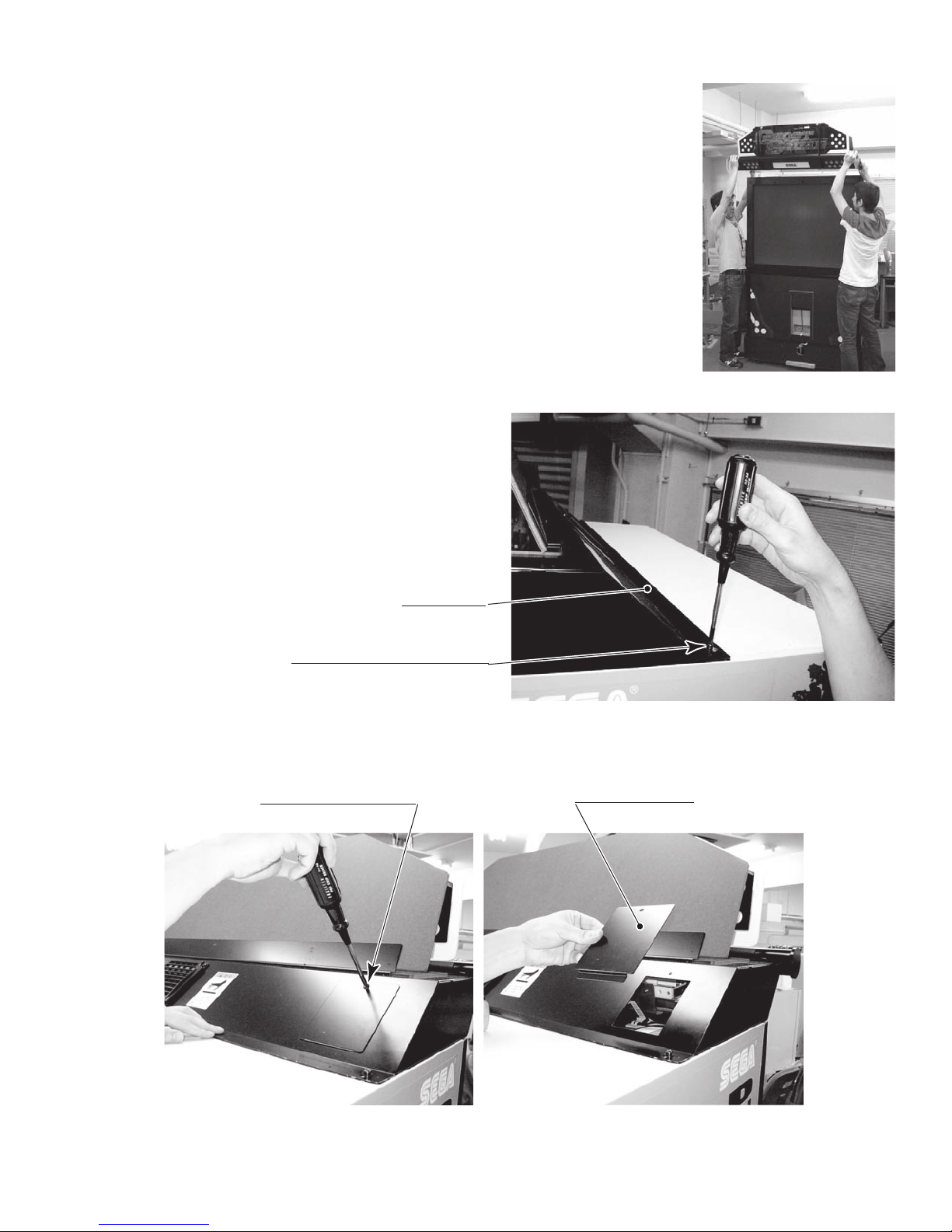
● Have 2 people lift the billboard and place it on the PTV. Lower the
billboard so that the two mask bracket uppers that were attached in step
2 fit into the 2 rectangular holes in the billboard base plate, and push the
billboard towards the PTV screen. The base plate of the billboard is then
fixed into place by fitting into the mask brackets.
You will need 2 people to perform this step.
● You will need a footstool to complete the
following step. Attach the billboard to the
PTV using 2 screws.
PHOTO 6. 3 b
BILLBOARD
SCREW (2) t
M5×16, w/flat & spring washers
You will need a footstool to
perform this step.
● Undo the single truss screw and remove the connector lid.
TRUSS SCREW (1), black
M4×8
PHOTO 6. 3 c
CONNECTOR LID
PHOTO 6. 3 d
23
www.sauservice.com
 Loading...