

Sega Crazy Taxi High Roller, GDX-0002B Installation & Service Manual
420-6758-01UK REV 0
INSTALLATION & SERVICE MANUAL
Before using this product, read this SERVICE MANUAL carefully to understand the contents stated herein.
After reading this manual, be sure to keep it available nearby the product or somewhere convenient in
order to be able to refer to it whenever necessary.
Manufactured in the UK by:
MANUFACTURING DIVISION (UK)

CONTENTS
1.
BEFORE USING THIS PRODUCT........................................................................................................3
1.1. INSPECTIONS IMMEDIATELY AFTER TRANSPORTING THE PRODUCT TO THE LOCATION..4
2.
INTRODUCTION TO THIS SERVICE MANUAL ...................................................................................6
3.
INSTALLATION AND MAINTENANCE INSTRUCTIONS .....................................................................7
3.1. HANDLING AND INSTALLATION PRECAUTIONS ..........................................................................7
3.2. COIN HANDLING...............................................................................................................................7
3.3. NAME OF PARTS..............................................................................................................................8
3.4. ACCESSORIES .................................................................................................................................9
3.5. SHIPPING THE GAME BOARD.......................................................................................................10
3.6. SHIPPING THE MEDIA BOARD......................................................................................................12
3.7. ASSEMBLY INSTRUCTIONS..........................................................................................................13
3.7.1. INSTALLING THE BILLBOARD................................................................................................14
3.7.2. SECURING IN PLACE (LEG ADJUSTER ADJUSTMENT)......................................................17
3.7.3. FITTING THE SEAT .................................................................................................................19
3.7.3.1. Introduction:.......................................................................................................................19
3.7.3.2. Kit contents:.......................................................................................................................19
3.7.3.3. Installation instructions:......................................................................................................19
3.7.4. COIN HANDLING INSTALLATION...........................................................................................20
3.7.4.1. WIRING CONNECTIONS..................................................................................................21
3.7.5. CONNECTION TO THE POWER SUPPLY..............................................................................22
3.8. ASSEMBLY CHECK.........................................................................................................................23
3.8.1. MEMORY TEST........................................................................................................................23
3.8.2. C.R.T. TEST .............................................................................................................................24
3.8.3. INPUT TEST .............................................................................................................................25
3.8.4. OUTPUT TEST .........................................................................................................................26
3.9. MOVING THE MACHINE.................................................................................................................27
3.10. CONTROL PANEL (HANDLE MECHA.) - ‘HAPP’ TYPE ............................................................28
3.10.1. REPLACING VOLUME..........................................................................................................28
3.10.2. GREASING – SEGA and HAPP types ..................................................................................30
3.10.3. REPLACEMENT OF SPRING...............................................................................................30
3.11. SHIFT LEVER...............................................................................................................................31
3.11.1. REMOVING SHIFT LEVER...................................................................................................31
3.11.2. SWITCH REPLACEMENT ....................................................................................................32
3.11.3. GREASING............................................................................................................................32
3.12. ACCELERATOR AND BRAKE.....................................................................................................33
3.12.1. REMOVING THE ACCELERATOR AND BRAKE.................................................................33
3.12.2. ADJUSTING OR REPLACING THE VOLUME .....................................................................35
3.12.3. GREASING............................................................................................................................36
3.13. REPLACEMENT OF FLUORESCENT LAMPS............................................................................37
3.13.1. FRONT FLUORESCENT: .....................................................................................................37
3.14. GAME BOARD .............................................................................................................................39
3.14.1. TAKING OUT THE GAME BOARD.......................................................................................39
3.14.2. REMOVING THE GD-ROM DRIVE.......................................................................................41
3.15. COMPOSITION OF THE GAME BOARD ....................................................................................42
3.16. TROUBLESHOOTING .................................................................................................................43
3.17. FUSES..........................................................................................................................................44
4.
PERIODIC CHECK AND INSPECTION ..............................................................................................45
4.1. CLEANING THE CABINET SURFACES..........................................................................................45
5.
CONTENTS OF GAME .......................................................................................................................46
5.1. Playing the Game.............................................................................................................................47
5.2. Game Modes....................................................................................................................................50
6.
EXPLANATION OF TEST DATA AND DISPLAY................................................................................51
6.1. INTERNAL SWITCHES AND COIN METERS.................................................................................52
6.2. SYSTEM TEST MODE.....................................................................................................................53
6.2.1. EXPLANATION OF TEST AND DATA DISPLAY .....................................................................53
6.2.2. SYSTEM TEST MENU MODE..................................................................................................54
6.2.3. MEDIA BOARD TEST...............................................................................................................55
6.2.4. SYSTEM INFORMATION.........................................................................................................56
6.2.5. JVS TEST .................................................................................................................................57
6.2.6. INPUT TEST Screen.................................................................................................................58
i

6.2.7.
6.2.8. C.R.T. TEST .............................................................................................................................60
6.2.9. COIN ASSIGNMENTS..............................................................................................................61
6.2.10. CLOCK SETTING .................................................................................................................64
6.2.11. NETWORK SETTING (CORE) .............................................................................................65
6.2.12. NETWORK SETTING (MEDIA) ............................................................................................66
6.3. GAME TEST MODE.........................................................................................................................70
6.3.1. INPUT TEST .............................................................................................................................71
6.3.2. OUTPUT TEST .........................................................................................................................72
6.3.3. GAME ASSIGNMENTS ............................................................................................................73
6.3.4. I/O RANGE SETTING...............................................................................................................74
6.3.5. SOUND VOLUME SETTING ....................................................................................................75
6.3.6. BOOKKEEPING........................................................................................................................76
6.3.7. BACKUP DATA CLEAR............................................................................................................81
7.
7.1. INTRODUCTION..............................................................................................................................82
7.1.1. PRICE OF PLAY SETTINGS UK .............................................................................................84
7.1.2. PRICE OF PLAY SETTINGS EURO ........................................................................................85
7.1.3. PRICE OF PLAY SETTINGS Austria-Czech-Denmark-Norway-Israel-France2 ......................86
8.
9.
9.1. CTH-0000UK TOP ASSY CRAZY TAXI 3 HR .................................................................................88
9.2. CTH-1000UK ASSY UR CABI..........................................................................................................89
9.3. NOB-1100UK ASSY FRAMEWORK UR..........................................................................................93
9.4. NOA-1200UK ASSY CRT COVER UK.............................................................................................94
9.5. CTA-1150UK ASSY CC BOX WW ..................................................................................................95
9.6. NOA-1300UK ASSY BILLBOARD...................................................................................................96
9.7. CTH-1400UK ASSY FRONT PANEL ...............................................................................................97
9.8. CTH-1500UK ASSY FLOOR............................................................................................................98
9.9. NOB-1710UK ASSY AC UNIT NEW................................................................................................99
9.10. NOA-1750UK ASSY SERVICE DOOR.......................................................................................100
9.11. NOB-1950UK ASSY SFMD WHITE (FLAT DOOR) ...................................................................101
9.12. CTH-2000UK ASSY CONTROL PANEL ....................................................................................102
9.13. CTH-2200UK ASSY WOOFER ..................................................................................................104
9.14. CTH-4000UK ASSY ELEC .........................................................................................................105
9.15. CTH-4100UK ASSY MAIN BD....................................................................................................106
9.16. CTA-4200UK ASSY XFMR.........................................................................................................107
9.17. CTH-5000UK ASSY SEAT CTH.................................................................................................108
9.18. CTA-6001UK ASSY WIRE L ......................................................................................................109
9.19. NOB-6001UK ASSY WIRE L......................................................................................................109
9.20. CTA-6002UK ASSY WIRE R......................................................................................................109
9.21. CTH-INST...................................................................................................................................110
10. APPENDIX A - ELECTRICAL SCHEMATIC......................................................................................111
10.1. WIRE COLOURS .......................................................................................................................111
10.2. ELECTRICAL SCHEMATIC .......................................................................................................111
SOUND TEST...........................................................................................................................59
COIN MECH INSTALLATION AND CREDIT BOARD SET UP...........................................................82
DESIGN RELATED PARTS.................................................................................................................87
PARTS LIST ........................................................................................................................................88
ii
1. BEFORE USING THIS PRODUCT
To ensure the safe usage of the product, be sure to read the following before using the product. The
following instructions are intended for the use of QUALIFIED SERVICE PERSONNEL ONLY
reading and sufficiently understanding the instructions should any activity be carried out on the product. Only
qualified service personnel should carry out maintenance on the product.
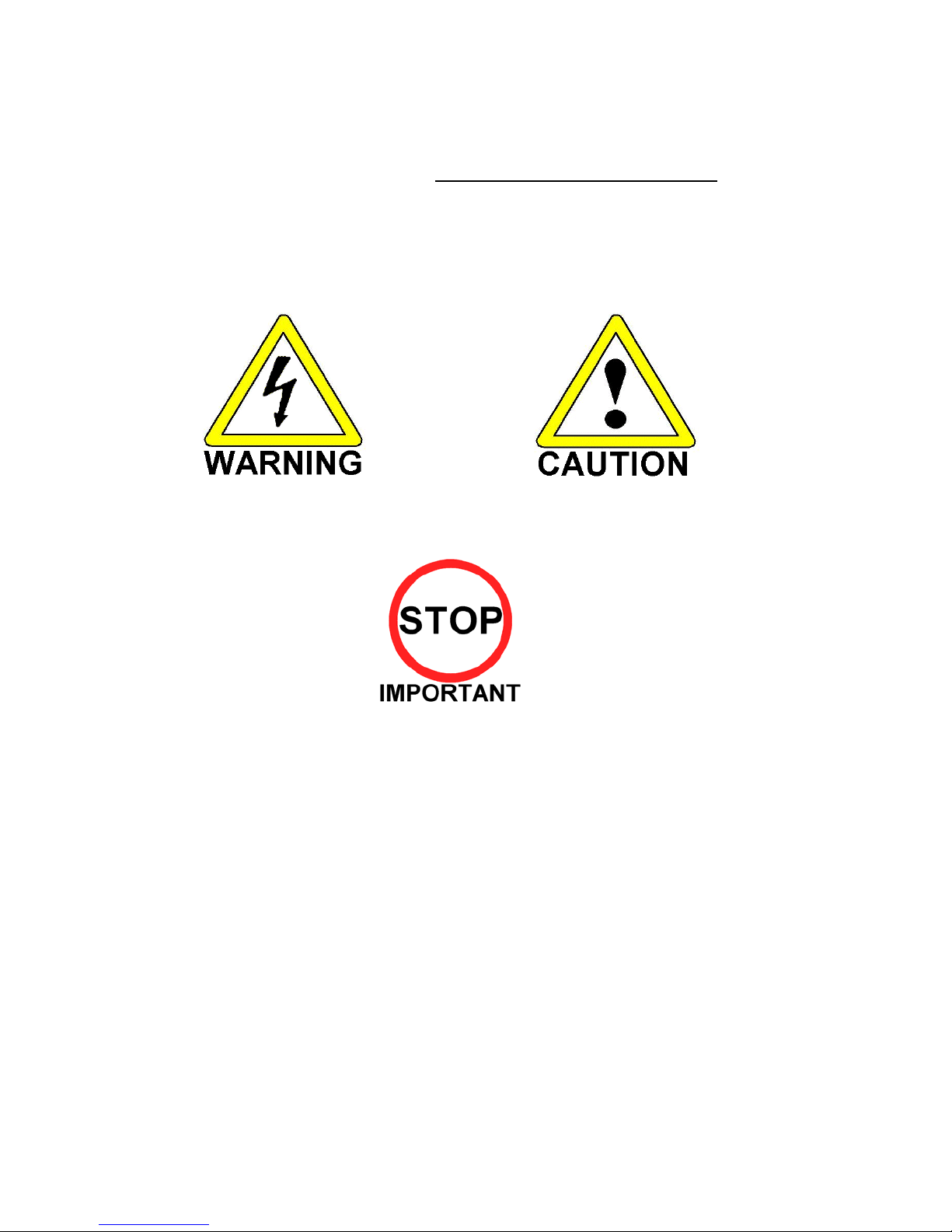
Terms such as WARNING!, CAUTION, and IMPORTANT! Are used where an explanation is given which
requires special attention, depending on the potential risk. SEGA is not responsible for injury or damage
caused by use in a manner contrary to the instructions stated in this document. In order to prevent accidents
warning stickers and printed instructions are applied in the places where a potentially hazardous situation
relating to the product could arise. Be sure to comply with these warnings.
. After carefully
Indicates that mishandling the product by
disregarding this warning will cause a potentially
hazardous situation, which can result in death or
serious injury.
This is cautionary information that should be complied with when handling the product. Indicates that
mishandling the product by disregarding this will cause a potentially hazardous situation that may not result
in personal injury but could damage the product.
Be sure to turn off the power and disconnect from the mains supply before working on the machine.
Ensure that the correct fuse(s) is fitted to the machine.
Details of the correct fusing of the machine are enclosed in the Service Manual.
Ensure that only qualified Service Engineers perform any maintenance work on the machine.
Specification changes, removal of equipment, conversion and/or addition, not designated by SEGA are not
permitted and will invalidate this product’s CE conformity.
The parts of the product also include any warning labels or safety covers for personal protection etc. A
potential hazard will be created if the machine is operated while any parts have been removed. Should any
doors, lids or protective covers be damaged or lost, do not operate the product. SEGA is not liable in any
whatsoever for any injury and/or damage caused by specification changes not designated by SEGA.
Before installing the product, check for the Electrical Specification Sticker, SEGA products have a sticker on
which the electrical specifications are detailed. Ensure that the product is compatible with the power supply
voltage and frequency requirements of the location in which the machine is to be installed.
Install and operate the machine only in places where appropriate lighting is available, allowing warning
stickers to be clearly read.
To ensure maximum safety for both customers and operators, stickers and printed instructions describing
potentially hazardous situations are applied to places where accidents could occur. Ensure that where the
product is operated has sufficient lighting to allow any warnings to be read. If any sticker or printed warning
is removed or defaced, do not operate the machine, until it has been replaced by an identical item.
When handling the monitor, be very careful. (Applies only to product with monitor)
Indicates that mishandling the product by
disregarding this caution will cause a potentially
hazardous situation, which can result in personal
injury and or material damage.
3
Some of the monitor (TV) parts are subject to high tension voltage. Even after turning off the power some
components are still occasionally subject to high tension voltage. Monitor repair and replacement should be
performed by qualified service engineers only.
In cases where commercially available monitors and printers are used only the contents relating to this
product are stated in this manual. Some commercially available equipment has functions and reactions not
stated in this manual. Read this manual in conjunction with the specific manual of such equipment.
Descriptions contained herein may be subject to change without prior notification.
The contents described herein are fully prepared with due care. However, should any question arise or
errors be found please contact SEGA.
1.1. INSPECTIONS IMMEDIATELY AFTER TRANSPORTING THE PRODUCT
TO THE LOCATION
Only QUALIFIED SERVICE PERSONNEL should carry out inspection.
·
Normally, at the time of shipment, SEGA products are in a state to allowing usage immediately after
transporting to the location. Nevertheless, an irregular situation may arise during transportation preventing
this. Before turning on the power, check the following points to ensure that the product has been transported
safely.
Are then any dented parts or defects (cuts, etc.) on the external surfaces of the product.?
·
Are castors and leg adjusters present and undamaged?
·
Do the power supply voltage and frequency requirements meet with the local supply?
·
Are all wiring connectors correctly and securely connected? Unless connected in the correct direction,
·
connector connections cannot be made successfully. Do not insert connectors forcibly.
Are all IC’s of each IC BD firmly inserted?
·
Does the power cord have any cuts or dents?
·
Do fuses meet the specified rating?
·
Are such units such as monitors, control equipment, IC BD, etc. firmly secured?
·
Are all earth wires connected?
·
Are all accessories available?
·
Can all doors and lids be opened with the accessory keys and/or tools?
·
4
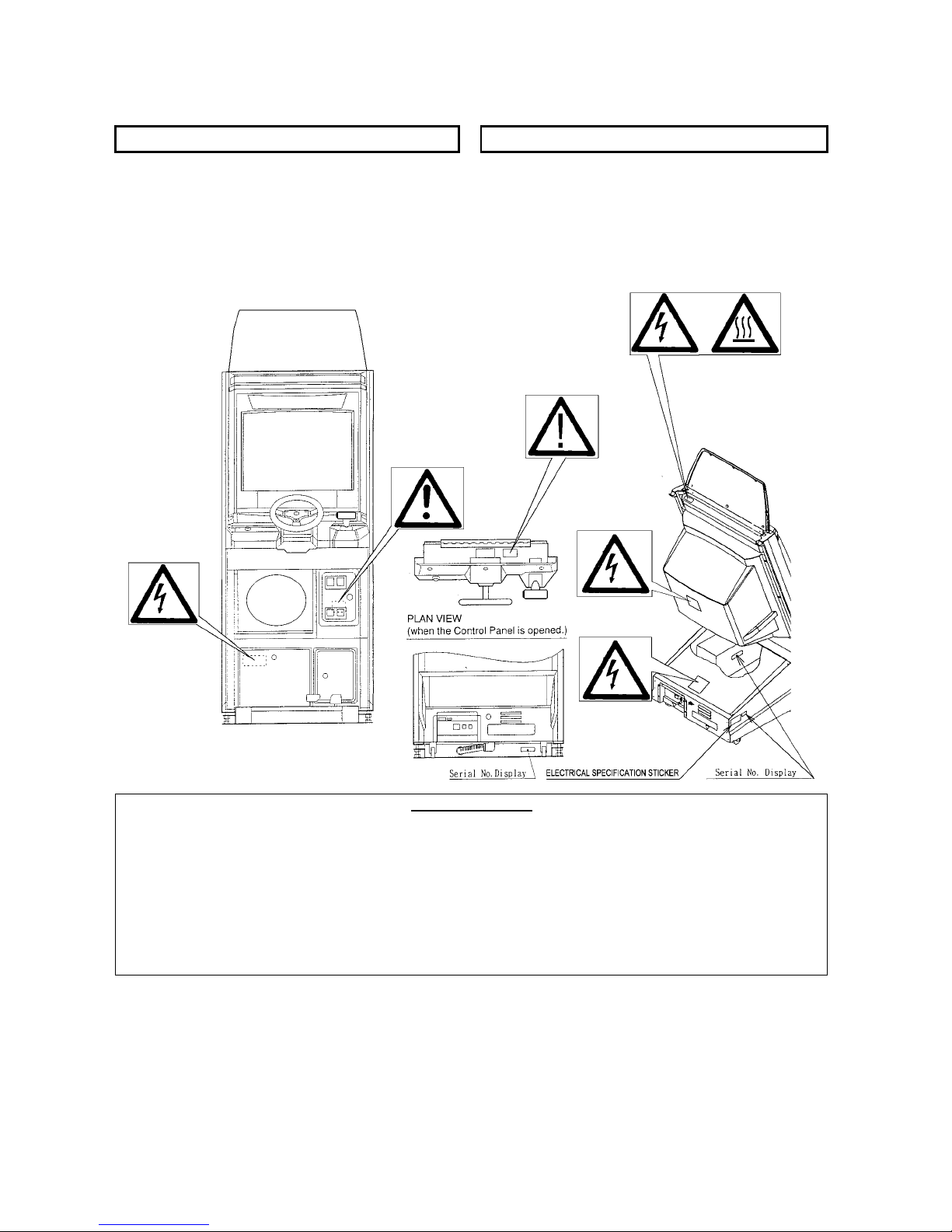
CONCERNING THE STICKER DISPLAY CONCERNING WARNING STICKERS
SEGA product has stickers describing the product
manufacture number (Serial Number) and
electrical specification. If you require service
assistance you will require the Serial Number.
Identical machines may have different parts fitted
internally. Only by quoting the Serial Number will
SEGA product has warning displays on stickers,
labels or printed instructions adhered/attached to
or incorporated in the places where hazardous
situations can arise. The warning displays are
intended for the accident prevention of customers
and service personnel.
the correct parts be identified.
Installation Space (cm): 80 (W) x 150 (D)
Height (cm): 225
Weight (kg): Approx. 200, when assembled with seat
Rated Voltage (VAC): 230V AC
Rated Current (A): 2 A
Operating Temperature Range 5 – 40º C
Note: Descriptions in this manual are subject to change without prior notice.
5
SPECIFICATIONS

2. INTRODUCTION TO THIS SERVICE MANUAL
SEGA ENTERPRISES LTD., supported by its experience in electronic high technology of VLSI’s,
microprocessors etc. and with a wealth of experience, have for more than 30 years been supplying various
innovative and popular games to the world market. This Service Manual is intended to provide detailed
descriptions together with all the necessary information covering the general operation of electronic
assemblies, electro-mechanicals, servicing controls, spare parts, etc. as regards this new SEGA product.
This manual is intended for those who have knowledge of electricity and technical expertise especially in
IC’s, CRT’s, microprocessors etc. Carefully read this manual to acquire sufficient knowledge before
working on the machine. Should there be any malfunction, non-technical personnel should under no
circumstances touch the internal systems. Should such a situation arise contact the nearest branch listed
below, or our head office.
SEGA AMUSEMENTS EUROPE LTD./ SEGA SERVICE CENTRE
Suite 3a
Oaks House
12 - 22 West Street
Epsom
Surrey
United Kingdom
KT18 7RG
Telephone: +44 (0) 1372 731820
Fax: +44 (0) 1372 731849
6
3. INSTALLATION AND MAINTENANCE INSTRUCTIONS
· Only QUALIFIED SERVICE PERSONNEL should carry out installation and
maintenance.
3.1. HANDLING AND INSTALLATION PRECAUTIONS
When installing or inspecting the machine, be very careful of the following points and pay attention to ensure
that the player can enjoy the game safely.
The game must NOT
· Outside, the game is designed for indoor use only.
· In areas directly exposed to sunlight, high humidity, dust, excessive heat or extreme cold.
· In locations that would present an obstacle in the case of an emergency i.e. near fire equipment or
emergency exits.
· On unstable surfaces or surfaces subject to vibration.
· Where liquids, other than routine cleaning, may come into contact with the game.
Important:
· Only Qualified Service Personnel should install this machine.
· Be sure to switch the supply power OFF and remove the mains supply plug from the machine before any
work is carried out on the machine.
Do not attempt to repair the PCB’s (Printed Circuit Boards) yourself. This will void the warranty. The
·
PCB’s contain static sensitive devices that could be damaged.
Always return a faulty part to your distributor with adequate packaging and protection.
·
When removing the plug from the mains always grasp the plug not the cable.
·
Do not use a fuse that does not meet the specified rating.
·
Make sure all connections are secure before applying power.
·
be installed under the following conditions:
· Ensure that the mains lead is not damaged. If the mains lead is damaged in any
way there could be a danger of electric shock or a fire hazard.
Ensure that the power supply is fitted with circuit protection. Using the power
·
supply without circuit protection is a fire hazard.
3.2. COIN HANDLING
Standard Sega machines are fitted with a SR3 coin mechanism, however, as a service to our customers
Sega machines can be supplied with no coin mechanism or door allowing the customer to fit a coin handling
option from the approved list. Fit only the coin handling arrangements detailed below and follow the
instructions provided in section 4. Failure to fit the coin handling options detailed or failure to follow the
installation instructions will render the machine, under the CE marking directive, void.
Approved coin handling options:
Coin controls SR3
·
· Generic mechanical
· Mars (MS111B1 and ME115)
· SECI RM4-G20
7
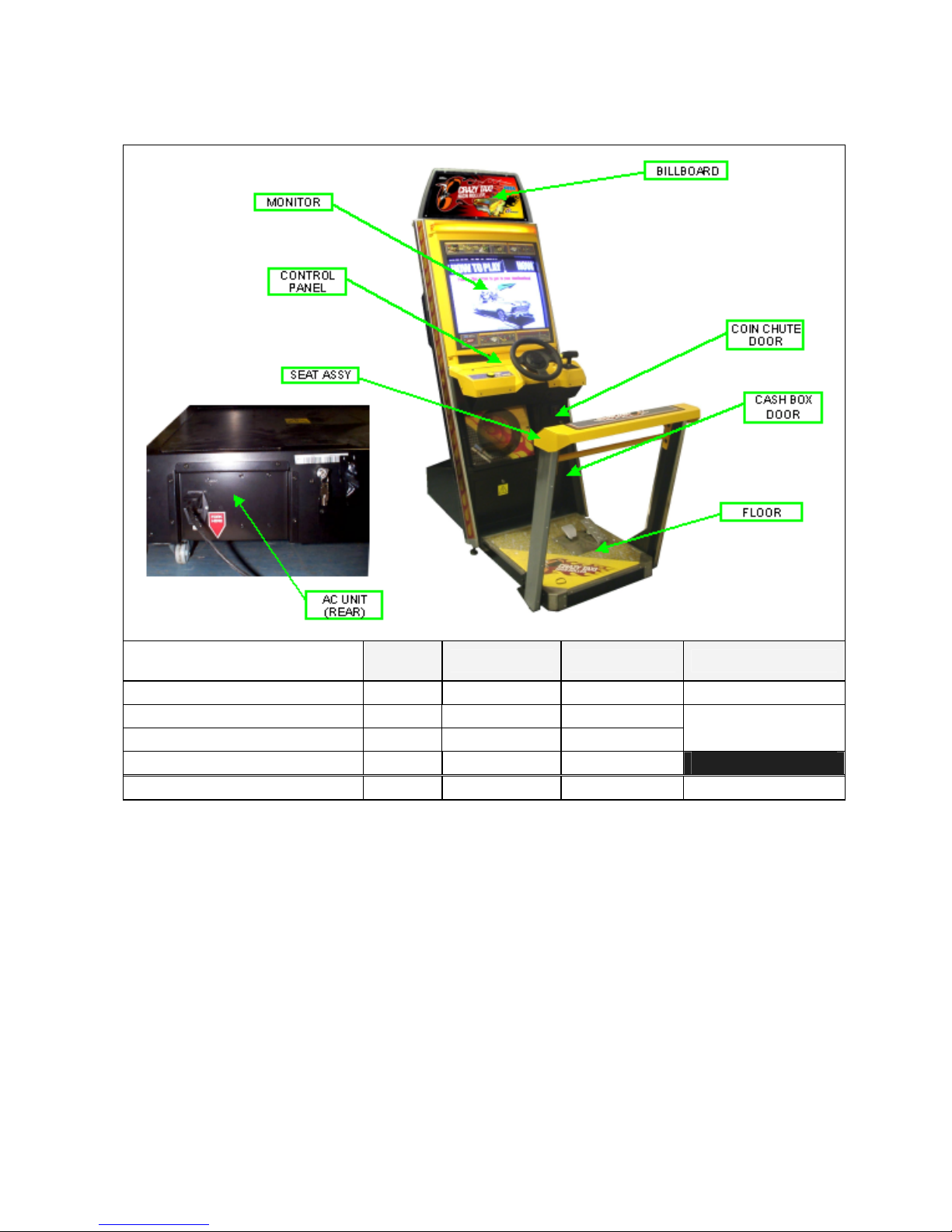
3.3. NAME OF PARTS
Width
(cm)
MAIN CABINET 76 105 180 165
FLOOR 63 71 15
SEAT 77 46 89
BILLBOARD 76 17 31
WHEN ASSEMBLED 76 147 224 200
Length (cm) Height (cm) Approx Weight (Kg)
35
8
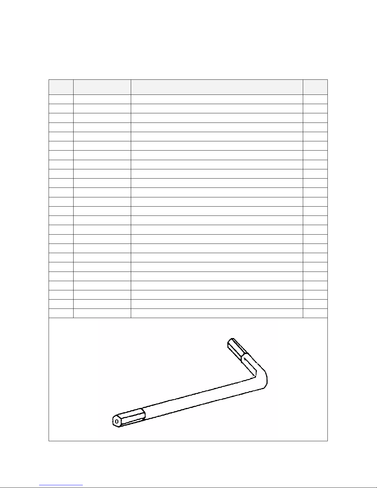
3.4. ACCESSORIES
The machine is supplied with an installation kit. Please ensure the following parts are supplied:
Item Component Part Description Qty
1 NOA-1301X ASSY BILLBOARD 1
2 CTH-1500UK ASSY FLOOR 1
3 CTA-0001 JOINT BRKT L 1
4 CTA-0002 JOINT BRKT R 1
8 CTH-0001UK DISPLAY CARD 1
9 NOA-1302UK BILLBOARD SHEET 1
14 CTH-0002UK PLAY INSTR SH A MULTI 1
16 CTH-0004UK SUB INSTR SH MULTI 1
18 420-5827 SERVICE MANUAL SANWA 31K 1
19 SAECE-XXX DECLARATION OF CONFORMITY 1
101 514-5078-5000 FUSE 5X20 CERAMIC SB 5000mA 1
201 030-000820-SB M8X20 BLT W/S BLK 2
202 068-852216-0B M8 WSHR 22OD FLT BLK 2
203
008-T00412-0C M4X12 TMP PRF TH CRM 5
402 420-6758-01UK SERVICE MANUAL CTH 1
403 420-6620UK SERVICE MANUAL GDROM 1
406 OS1019 SELF SEAL BAG 9X12.3/4 1
407 PK0325 INST KIT BOX CTH 1
408 PK0061 BUBBLE WRAP LARGE 1.5M X 45M 0.025
409 220-5484-H VOL 5-K-OHM HAPP 50-8026-00 1
411 540-0006-01 WRENCH M4 TMP PRF 1
412 540-0007-01 WRENCH M5 TMP PRF 1
413 540-0009-01 WRENCH M8 TMP PRF 1
414 540-0015-01 WRENCH M6 TMP PRF 1
Items 101 & 102 - Tamperproof TORX wrench.
9
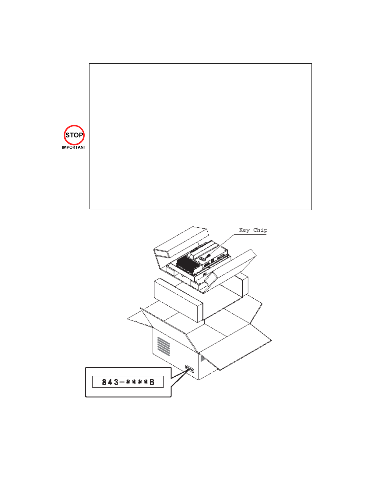
3.5. SHIPPING THE GAME BOARD
Replacement or repair of the Game Board (Chihiro) for this product should be undertaken at
the appropriate repair centre. Be sure to follow the specifications below when requesting
repairs/sending the board to the repair centre. Not following the specifications may result in
the board not being accepted or in extra charges being made.
Put the game board in the carton box as is. Do not carry out any disassembly or part
·
removal other than that specified.
· Follow the procedure and instructions regarding direction below when placing the Game
Board in the carton box.
· When packing the game board with the Media Board attached, do not remove the Key
Chip.
When packing the game board with the Media Board detached, be sure to include the
·
AVIP Cable.
When packing, attach the accessory stickers in the specified places on the Game Board
·
and carton box.
INSTRUCTIONS
1. Wrap the Chihiro Board in a plastic bag.
2. Place it on top of the bottom surface cushioning material. Turn the Filter Board to face the side with
the three honeycomb buffers. Packing it in the opposite direction may cause damage to the Filter
Board.
3. Insert corrugated cardboard into the space between the lateral honeycomb buffers of the bottom
surface cushioning material and stow the AVIP cable inside.
4. Place the Chihiro Board wrapped in the bottom surface cushioning material into the carton box. Use
the handles on the bottom surface cushioning material.
5. Place the upper surface cushioning material on top of the Chihiro Board. Be sure to align it in the
right direction, as it will not fit otherwise.
6. Close the top of the carton box and seal it tightly with adhesive tape.
10

11
3.6. SHIPPING THE MEDIA BOARD
When sending the Media Board for repairs, follow the specifications below and
request repairs or send the Board to your retailer/the repair centre.
Not following the specifications may result in the board not being accepted or in extra
charges being made. Also, mistaken handling can damage or result in loss of parts.
Be sure to use the special purpose carton box included with this product.
·
Do not remove the Key Chip. Send the board with the Key Chip attached.
·
Undo the 10 screws holding the Media Board to the Main Board and pack the
·
Media Board. Do not carry out any disassembly or part removal other than that
specified in this manual.
· Pack the Media Board in the special purpose carton box as shown in the
explanatory diagram.
· The packing material in the carton box has a shock absorbing function. Be sure
to use it when packing. Do not bend or fold the material in a direction other than
that shown on the diagram.
Do not pack any wires, cables, or screws together with the Board.
·
Be sure to attach the special purpose carton box accessory sticker
·
ãããã
"843-
B."
12
3.7. ASSEMBLY INSTRUCTIONS
Perform the assembly by following the procedure herein stated. Failure to comply
·
with the instructions, for example, inserting the plug into an outlet at a stage not
mentioned in this manual can cause an electric shock
· Assembling should be performed as per this manual. Since this is a complex
machine, erroneous assembling can cause damage to the machine, or
malfunction to occur.
Do not attempt to complete this work alone, a minimum of 2 people are required.
·
· Only QUALIFIED SERVICE PERSONNEL should carry out assembly.
When carrying out the assembly work, follow the procedure in the following sequence:
STEP 1 INSTALLING THE BILLBOARD
STEP 2 INSTALLING THE FLOOR
STEP 3 SECURING IN PLACE (LEG ADJUSTMENT)
STEP 4 FITTING SEAT
STEP 5 CONNECTION TO THE POWER SUPPLY
STEP 6 ASSEMBLY CHECK
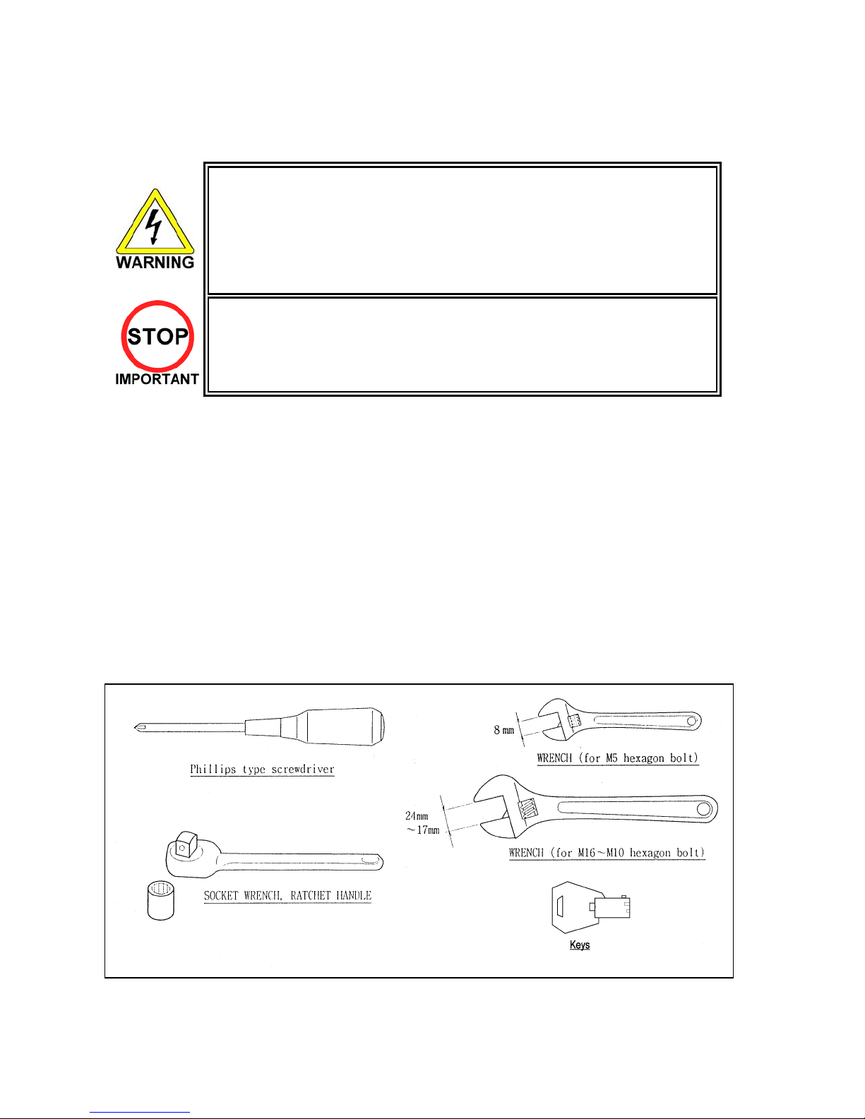
Note that the parts contained within the installation kit are required for the assembly work.
The following tools will be required when installing this machine:
13
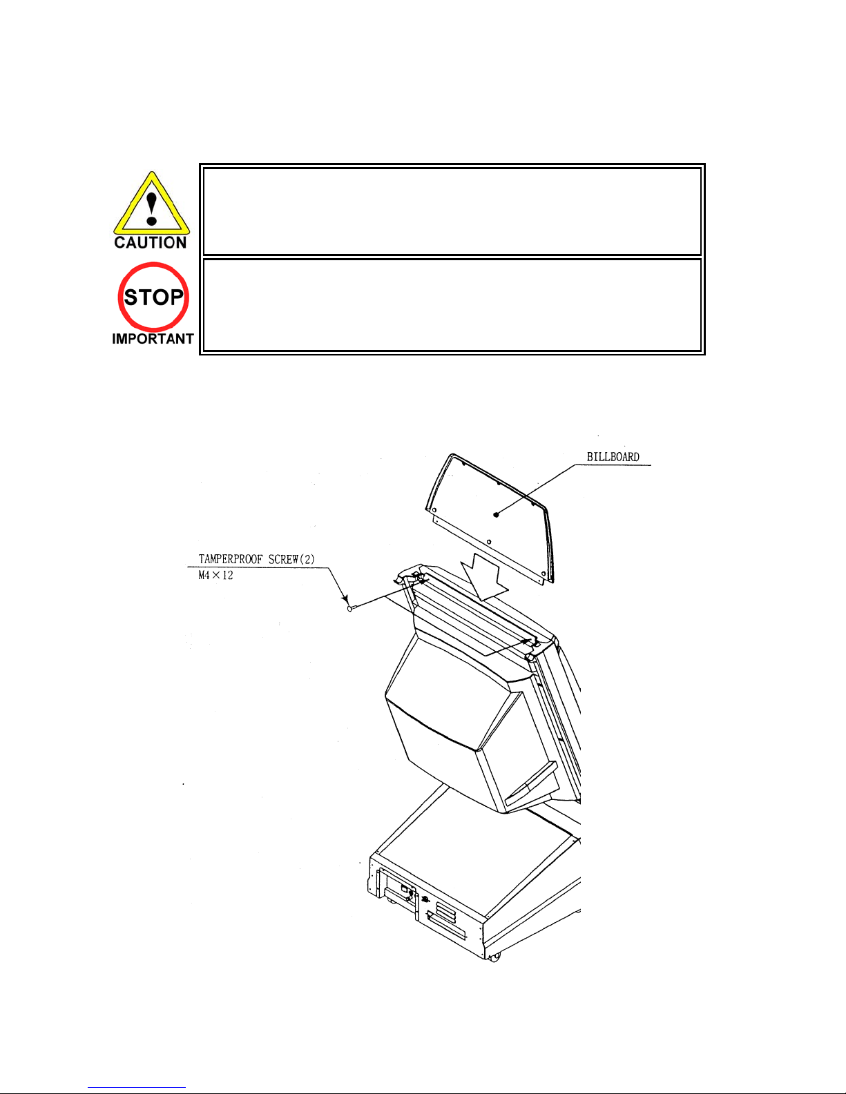
3.7.1. INSTALLING THE BILLBOARD
· To perform work safely, use a secure and stable step to improve access to the
top of the cabinet. Working without using a step may cause accidents.
Only QUALIFIED SERVICE PERSONNEL should carry out this operation.
·
1. Insert ASSY BILLBOARD to the top part of the cabinet
2. Secure with the two Tamperproof screws (Part No.
008-T00412-0B, supplied with Accessory kit)
14
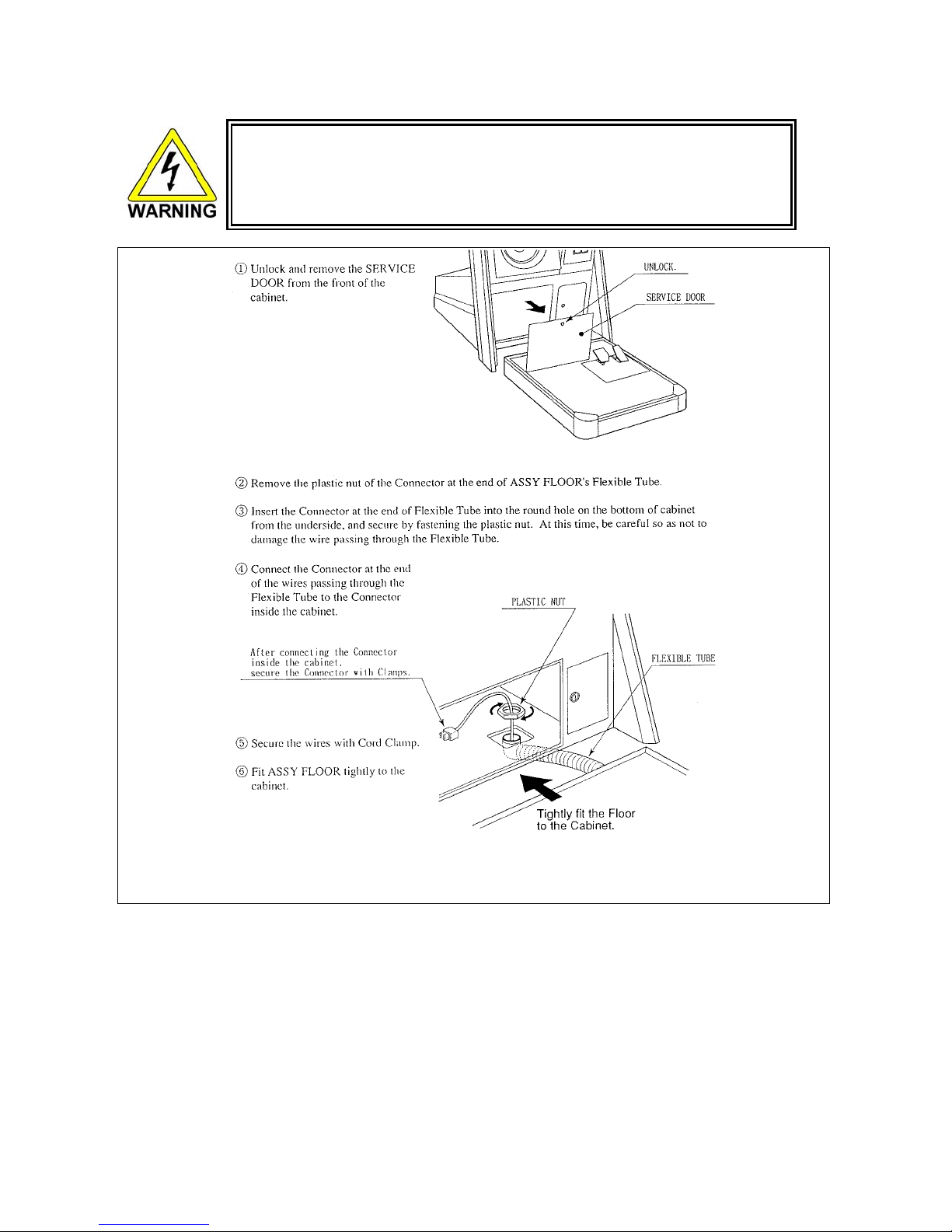
INSTALLING THE FLOOR
Ensure all connections are secure - poor connections can cause electric shock or
·
short circuit.
· Take care not to damage wiring during installation, as this can cause electric
shock or short circuit.
15
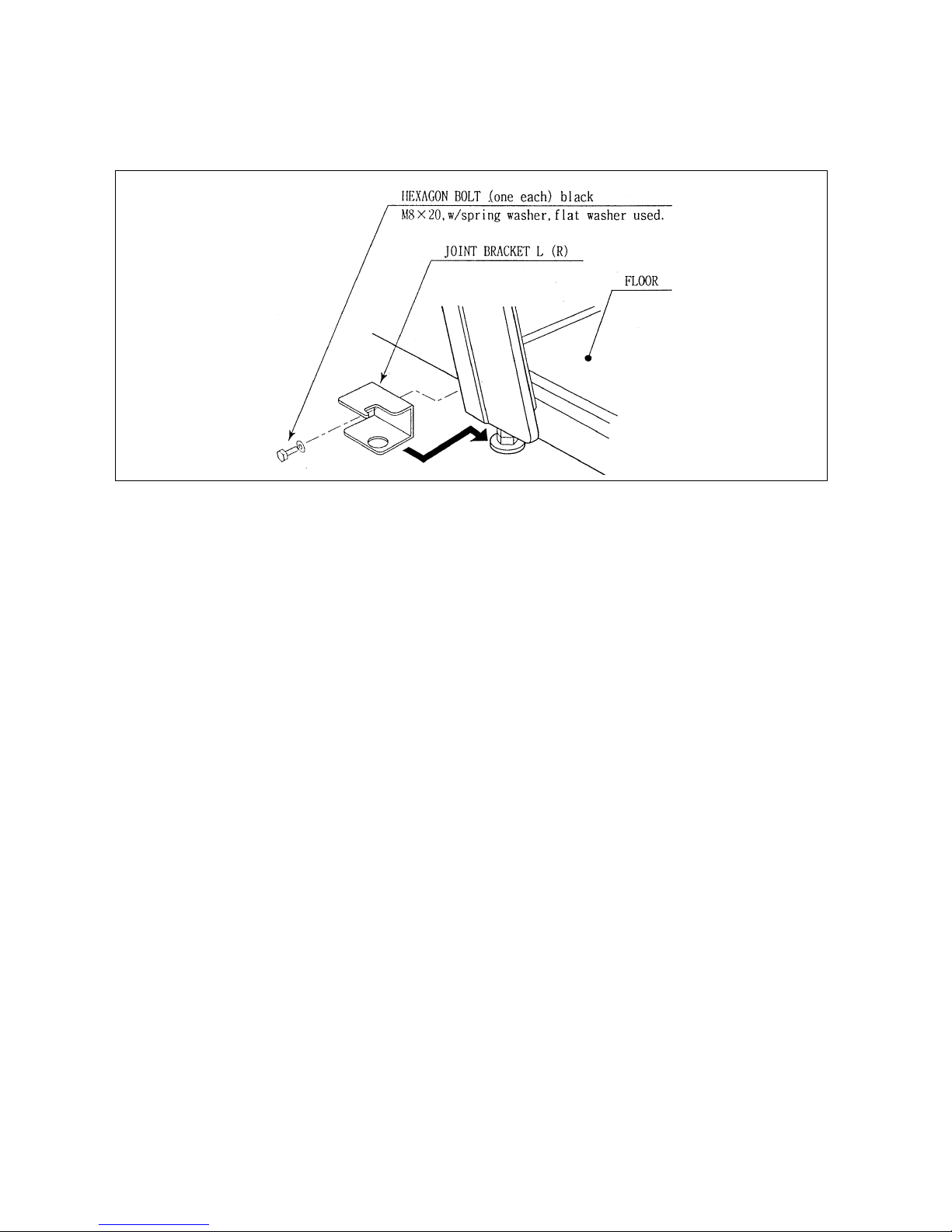
Slightly lower the 2 Adjusters on the cabinet and install JOINT BRACKET L & R by inserting from
the rear, and secure to ASSY FLOOR using hexagon bolts as shown.
After lowering the Adjusters fully downward, tighten both Adjuster’s lock nuts fully upward.
16
3.7.2. SECURING IN PLACE (LEG ADJUSTER ADJUSTMENT)
Make sure all of the leg adjusters are in contact with the floor. If they are not the
·
machine may move and cause injury. This operation requires 2 people.
· Only QUALIFIED SERVICE PERSONNEL should carry out this operation.
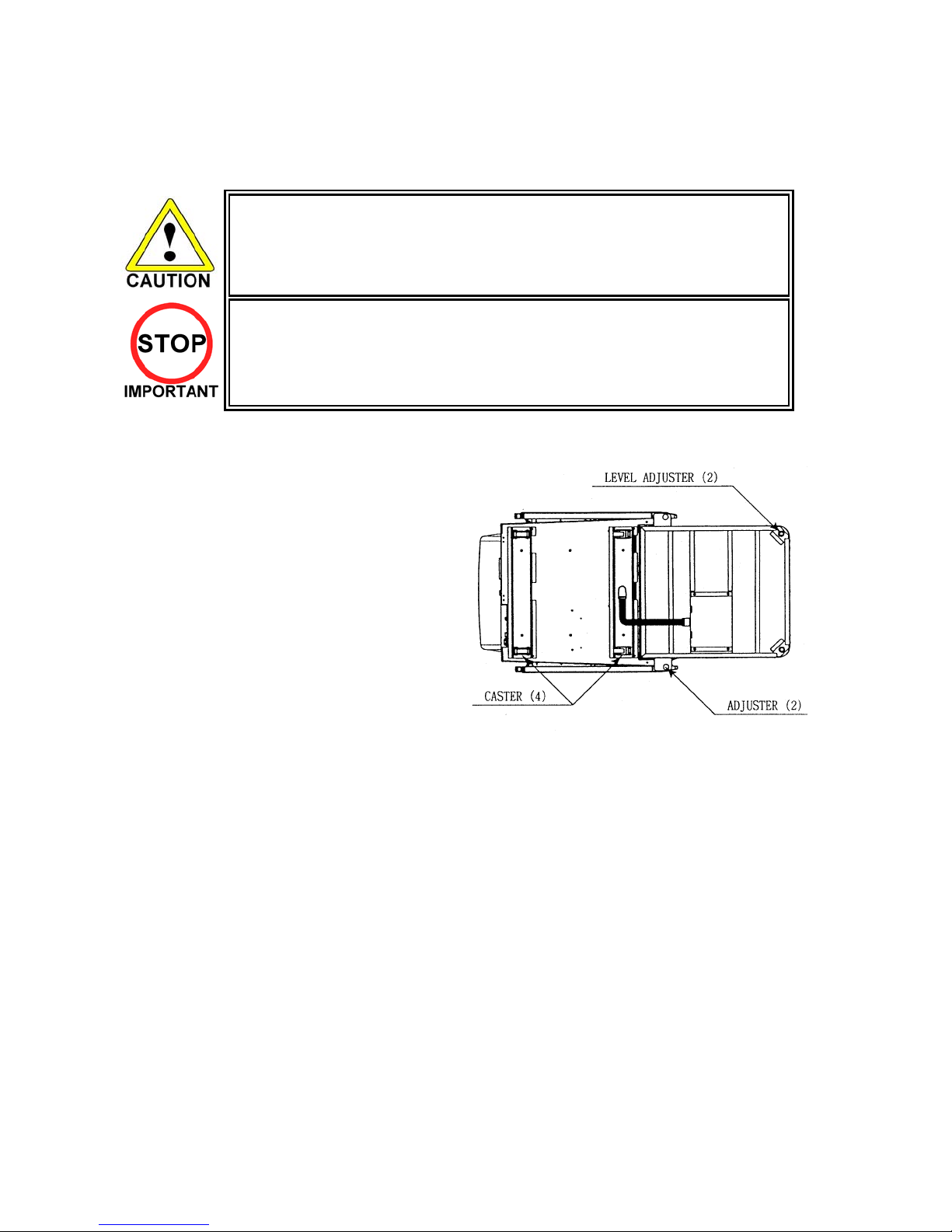
This machine has four castors and two leg adjusters on the main cabinet, and a further two level adjusters
on the rear of the floor. When the installation position is decided, unscrew the leg adjusters so that they
raise both front castors 7mm from the floor. Make sure the machine is level.
1. Move the product into the installed position.
2. Unscrew the adjusters until they are in contact
the floor, and use a wrench to turn them further
until the front castors are raised approximately
7mm above the floor.
3. Tighten the locknut on the leg adjusters upwards
to lock the legs in position.
17
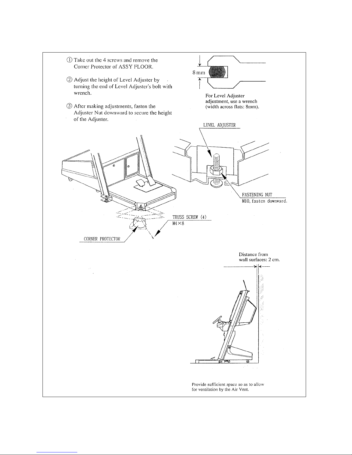
If this product is installed on irregular surfaces, use the two Level Adjusters on the bottom of the FLOOR to
ensure the product is level.
18
3.7.3. FITTING THE SEAT
3.7.3.1. Introduction:
This kit facilitates a lean-on REST for application to ROUTE 66 Standard. This REST allows pressure to be
taken off the left leg, which increases the length of time that a player may play the game without suffering
from fatigue.
3.7.3.2. Kit contents:
PART NUMBER DESCRIPTION QTY
CTA-5001UK SEAT FRAME R 1
CTA-5002UK SEAT FRAME L 1
CTA-5003UK SEAT FRAME COVER R 1
CTA-5004UK SEAT FRAME COVER R 1
CTA-5005UK SEAT BENCH PTR (with CTH cushion) 1
008-T00416-0C M4X16 MSCR TMP PRF TH CRM 10
030-000820-SB M8X20 BLT W/S BNP 8
068-852216-0B M8 WSHR FORM C FLT BNP 8
030-000616-SB M6X16 BLT W/S BNP 8
068-651416-0B M6 WSHR FORM C FLT BNP 8
3.7.3.3. Installation instructions:
A condition of fitting this REST is that the machine is fully fitted with items CTA-0001 &
·
CTA-0002 (JOINT BRKT L & R) as described in the 18 WHEELER Manual. Non-fitment
of these brackets may lead to injury, as there will be nothing to secure the floor to the
main cabinet. The REST relies on the floor being firmly secured to the main cabinet in
order to support the weight of the player when resting against the machine.
The REST utilises the weight of the main cabinet to prevent tipping. It is important that
·
this REST is used only to take the weight off the left leg. Sega accepts no responsibility
for injury arising due to inappropriate usage of the REST.
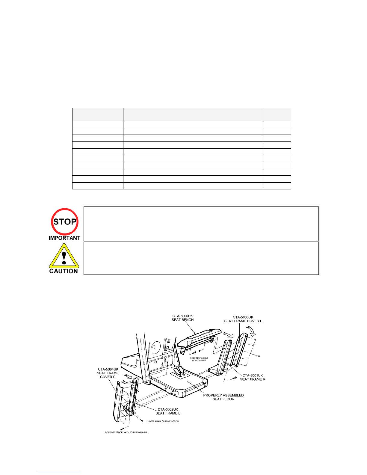
1. Fix the CTA-5001UK & CTA-5002UK SEAT FRAMES to the FLOOR ASSEMBLY (CTH-1500UK) using
the 8-off M8 bolts and washers provided as shown.
2. Fix the CTA-5003UK & CTA-5004UK SEAT FRAME COVERS to the SEAT FRAMES using the 10-off
M4 tamperproof machine screws provided as shown.
3. Fix the CTA-5005UK SEAT BENCH PTR between the SEAT FRAMES using the 8-off M6 bolts and
washers provided as shown. Loosely fit these bolts (top ones first) before tightening.
19
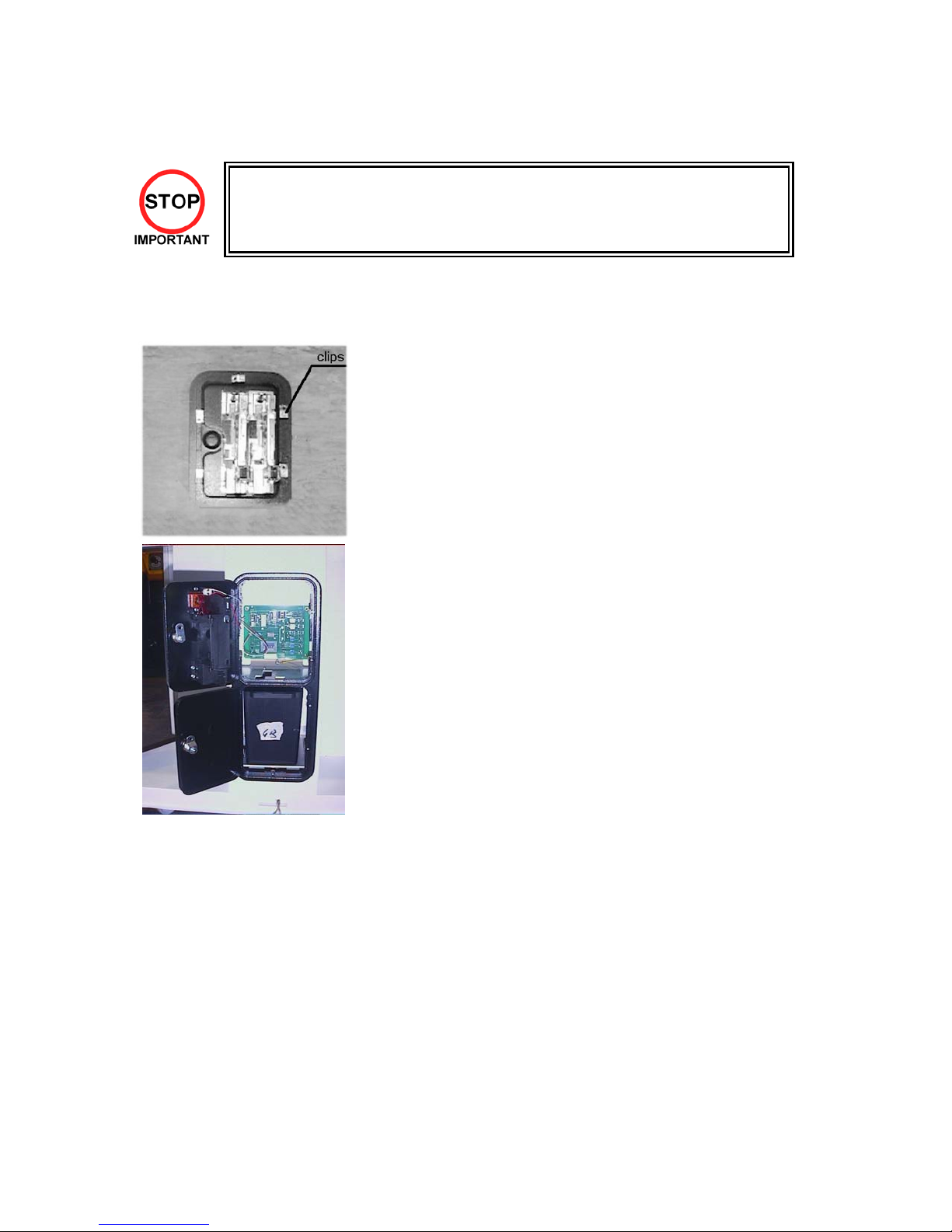
3.7.4. COIN HANDLING INSTALLATION
· Only QUALIFIED SERVICE PERSONNEL should carry out this operation.
When fitting the coin mechanism to the door please refer to the specific manufacturers installation
instructions for that coin mechanism. To fit the door to the machine follow the procedure below.
· Loosen all of the bolts on the frame that secure the clips.
· Turn all clips in towards the door.
Position the door into the aperture in the machine.
·
Turn the clips around so that they will hold the door in the
·
machine.
Tighten all of the bolts.
·
NOTE: DOUBLE FRAMED MINI DOOR SHOWN. SINGLE
FRAMED DOOR SIMILAR FITTMENT.
20
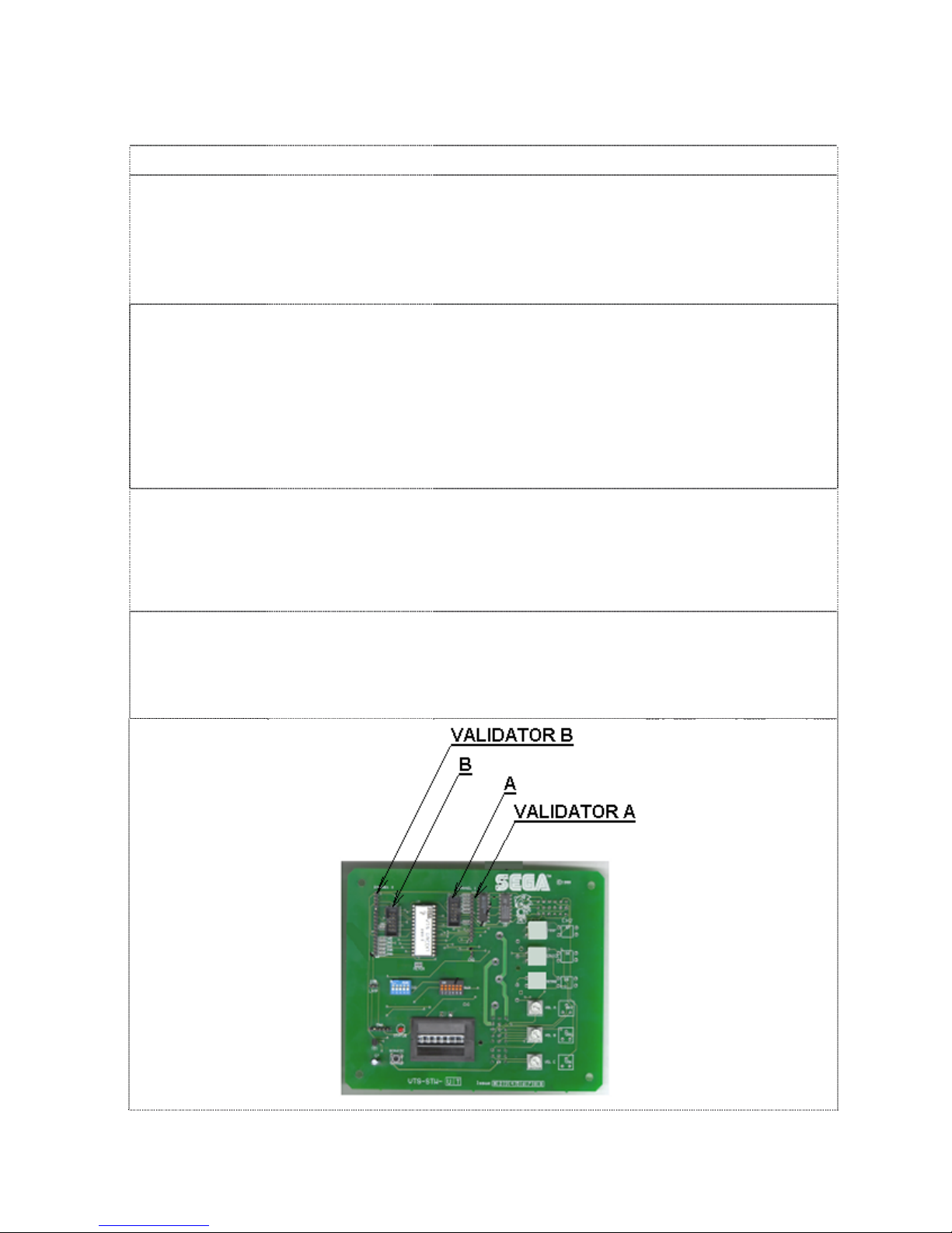
3.7.4.1. WIRING CONNECTIONS.
COIN MECH LOOM INSTALLATION
C220B LM1006IDC
LM1006LAMP-0.1
GENERIC
MECHANICALS
MARS MS111B1
MARS ME115
SECI, C120, SR3 OWN LOOM AND
LM1008
LM1008-LAMP
LM1007
LM1008-LAMP
LM1006LAMP-0.1
· Attach the lamp holder to the bracket on the coin return
button.
· Attach one 15-way connector to the C220 coin mech.
· Attach the other 15-way connector to Validator A on the
credit board.
· Attach the 2-way connector to ‘LAMP’ on the VTS board.
· Fit the two lamp holders behind the coin return buttons.
Attach the blue cable and orange cable to one mech’s
·
microswitch switch.
· Attach the blue/green cable and orange/green cable to the
other mech’s microswitch.
· Attach the 2-way mate and lok plug to the 2-way mate and
lok cap provided.
Attach one 15-way connector to Validator A and the other
·
to Validator B on the credit board
· Fit the lamp holder to the bracket behind the coin return
button.
Fit one of the 13-way connectors to the coin mech.
·
· Fit the other 13-way connector to Validator A on the credit
board. Note the 13-way connector is keyed and this key
must coincide with the key on the credit board.
· Attach the lamp holder to the bracket on the coin return
button.
Attach the 2- connector to ‘LAMP’ on the VTS board.
·
· Attach the validator’s own loom to position A on the credit
board
21
VTS credit board assembly
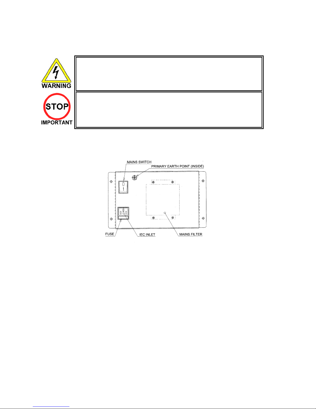
3.7.5. CONNECTION TO THE POWER SUPPLY
Be sure that the machine is not connected to the mains supply before attempting
·
this operation
· Only QUALIFIED SERVICE PERSONNEL should carry out this operation.
1. The AC Unit is located on the right hand side of the base unit, when viewing the screen. It houses the
IEC inlet, mains switch and fuse.
2. Ensure that all of the machine’s wires have been connected in accordance with the preceding sections
and that the mains switch is OFF.
3. Check that the operating voltage of the mains supply matches the machine (section 1.1).
4. Insert the IEC lead into the IEC inlet and the mains plug into a wall socket. If applicable, switch the wall
socket ON.
5. Stand clear of the machine and switch the mains switch ON.
22
3.8. ASSEMBLY CHECK
· Only QUALIFIED SERVICE PERSONNEL should carry out this operation.
In the TEST MODE, ensure that the assembly has been made correctly and IC Board is satisfactory (refer
to Section ).
In the test mode, perform the following test:
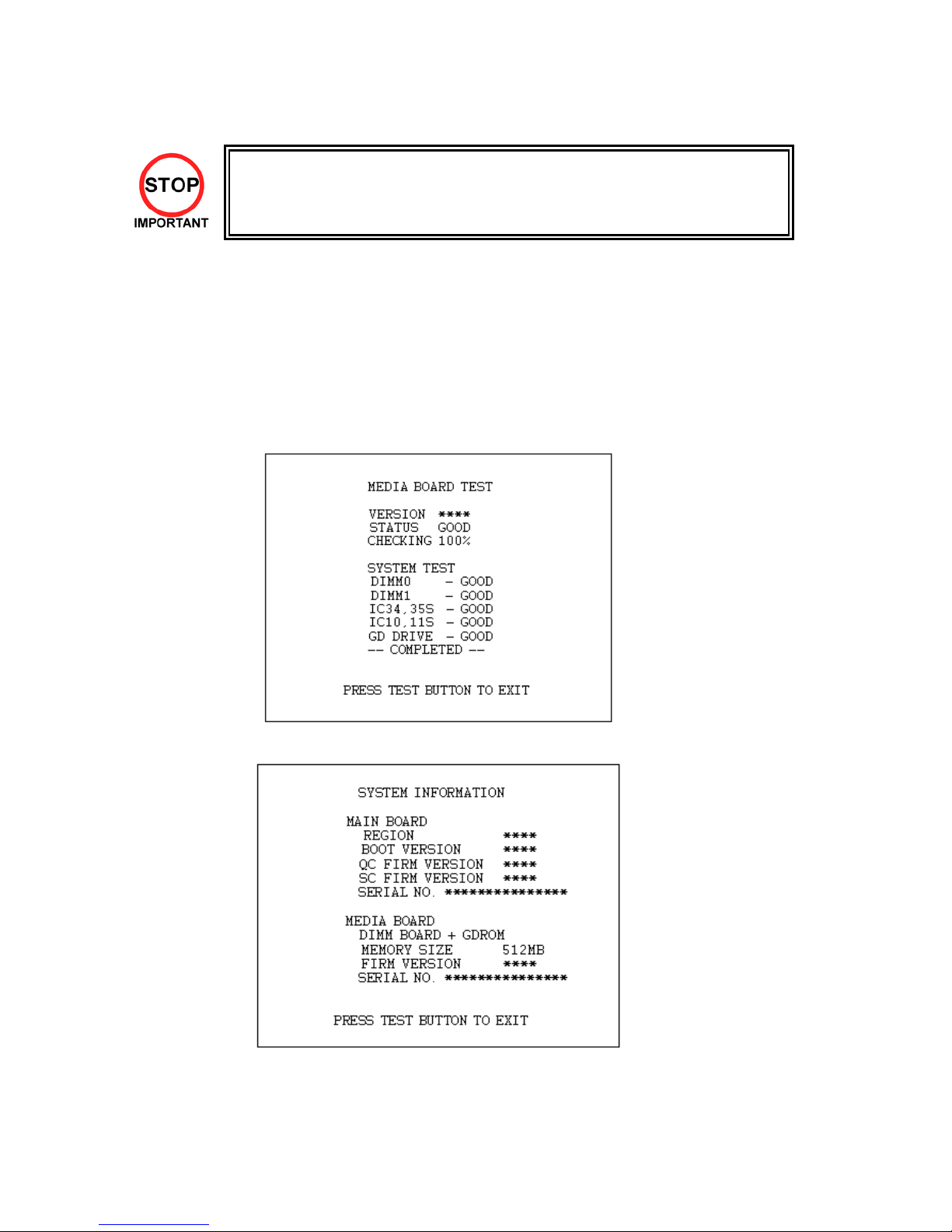
3.8.1. MEMORY TEST
When "MEDIA BOARD TEST" is selected from the System Test Mode Menu Screen the Game Board
memory is automatically tested. If the display beside each memory reads "GOOD", the Game Board is
functioning correctly.
Also, when "SYSTEM INFORMATION" is selected, Main Board and Media Board data for the Game Board
are displayed. If data is displayed correctly, the Game Board is functioning correctly.
MEDIA BOARD TEST screen
SYSTEM INFORMATION screen
23
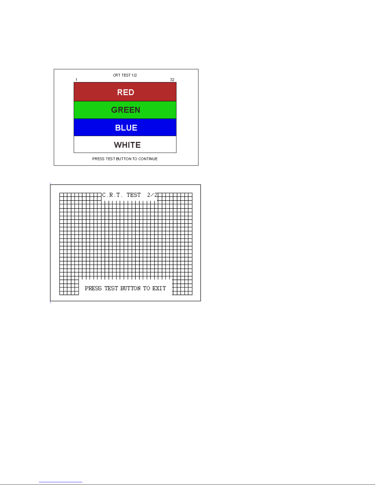
3.8.2. C.R.T. TEST
In the TEST mode menu, selecting
C.R.T. TEST allows the screen (on
which the moniter is tested) to be
displayed. Although the moniter
adjustments have been made at the
time of shipment from the factory,
make judgment as to whether an
adjustment is needed by watching
the test mode screen. If it is
necessary, adjust the moniter by
referring to Monitor manual.
24

3.8.3. INPUT TEST
Select INPUT TEST to display the following screen and check the status of input devices.
This test should be used periodically to check that each input device is functioning correctly.
Crazy Taxi HighRoller
¡
[GAME TEST MENU -INPUT TEST]
DRIVE GEAR OFF
REVERSE GEAR OFF
JUMP OFF
START OFF
SERVICE OFF
TEST OFF
WHEEL 7eH
ACCEL 2fH
BRAKE 2fH
-PRESS TEST BUTTON AND SERVICE BUTTON TO EXIT-
Operate the WHEEL (steering wheel), ACCEL (accelerator), and BRAKE (brake pedal) to check that the
values change appropriately and smoothly.
Input is normal if the display to the right of other each item changes from OFF to ON when each input
device is operated.
Press the SERVICE and TEST Buttons simultaneously to return to the Game Test Menu screen.
25

3.8.4. OUTPUT TEST
Select OUTPUT TEST to display the following screen and check the status of each lamp.
This test should be used periodically to check that the lamps are functioning correctly.
Crazy Taxi HighRoller
[GAME TEST MENU -OUTPUT TEST]
START BUTTON OFF
LAMP NO.1 OFF NOT USED
LAMP NO.2 OFF NOT USED
LAMP NO.3 OFF NOT USED
LAMP NO.4 OFF NOT USED
EXIT
-SELECT WITH SERVICE BUTTON AND PRESS TEST BUTTON-
Perform the tests as follows.
START BUTTON: Select START BUTTON and press the TEST Button. The display to the right of the
Move the cursor to EXIT and press the TEST Button to return to the Game Test Menu screen.
item will change to ON and the Start Button will flash.
26
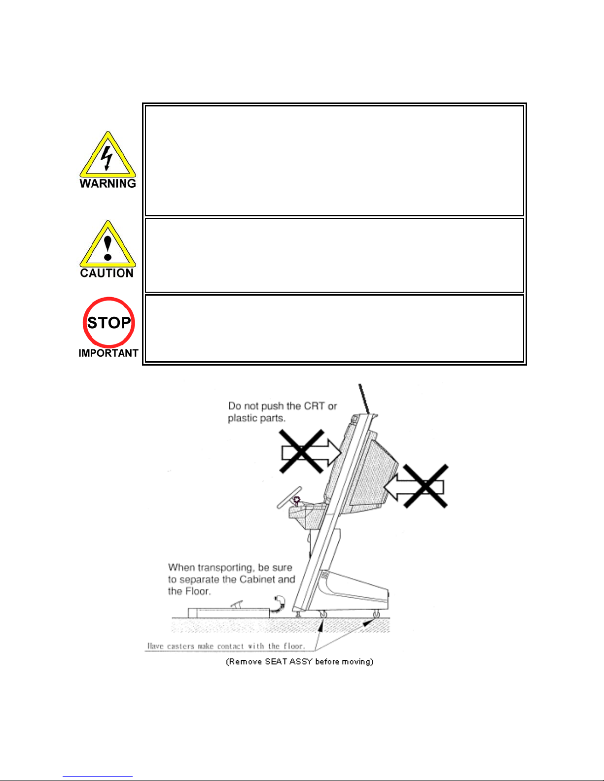
3.9. MOVING THE MACHINE
· When moving the machine, be sure to remove the plug from the power supply. Moving
the machine with the plug inserted can cause the power cord to be damaged, resulting
in a fire or electric shock.
When moving the machine, retract the leg adjusters fully and ensure the casters make
·
contact with the floor. During movement pay careful attention so that the casters or leg
adjusters do not damage any other cabling laid on the floor. Such damage could result
in a fire or electric shock.
Do not push the upper part of the cabinet. Failure to observe this can cause the
·
cabinet to fall forwards and result in accidents.
When transporting the machine, be sure to hold the catch portion on the rear of the
·
cabinet with the castors making contact with the surface as shown below. Inclining the
machine by holding portions other than the catch or moving the cabinet without
retracting the adjusters can damage the cabinet and/or the floor surface.
Do not push the Billboard. Failure to observe this may damage the installation portions
·
and may cause unexpected accidents.
Only QUALIFIED SERVICE PERSONNEL should carry out this operation.
·
27
(Remove SEAT ASSY before moving)
3.10. CONTROL PANEL (HANDLE MECHA.) - ‘HAPP’ TYPE
Before starting work, ensure that the cabinet is isolated from the mains by
·
switching off and removing the IEC mains lead from the wall outlet.
· Be careful not to damage wiring. Damaged wiring can cause electric shock and
short circuits.
When closing the Control Panel be very careful to avoid trapping fingers or hands.
·
Only QUALIFIED SERVICE PERSONNEL should carry out this procedure.
·
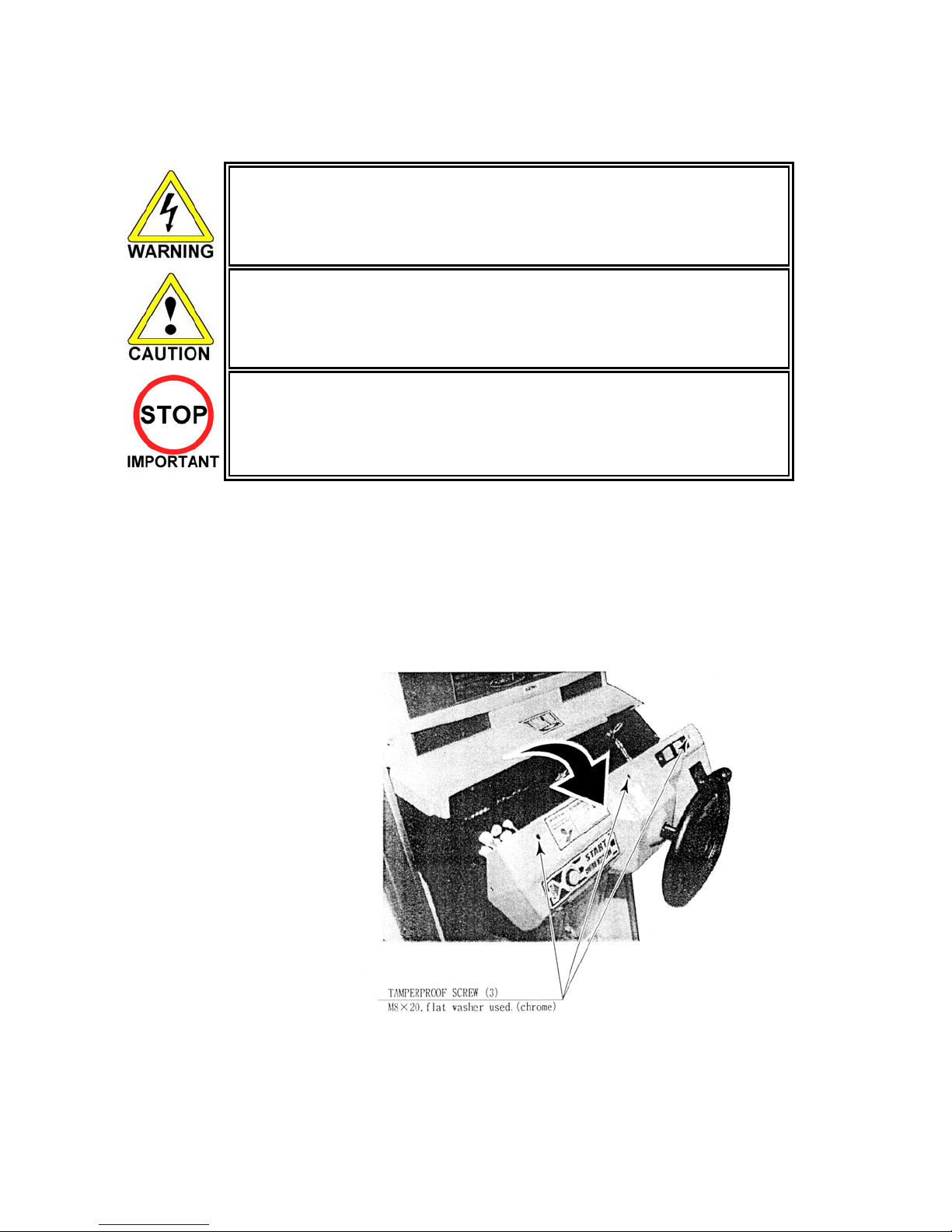
3.10.1. REPLACING VOLUME
If the steering operability becomes poor, and adjusting the VOLUME SETTING in the TEST MODE in
ineffective, the cause may be the failure of the Volume Gear to mesh and/or the Volume Potentiometer
malfunctioning.
When the Steering Wheel is rotated fully left or right, if the Volume shaft is rotating within the movable
range, the Volume is not feared to be damaged. Use the procedure described herein to position the
steering VR such that the correct centre value (refer to Section 5.3.5) is displayed when the Steering Wheel
is at rest.
1. Power OFF the machine and
remove the IEC lead from the
wall outlet.
2. Remove the three tamperproof
screws and open the Control
Panel.
28
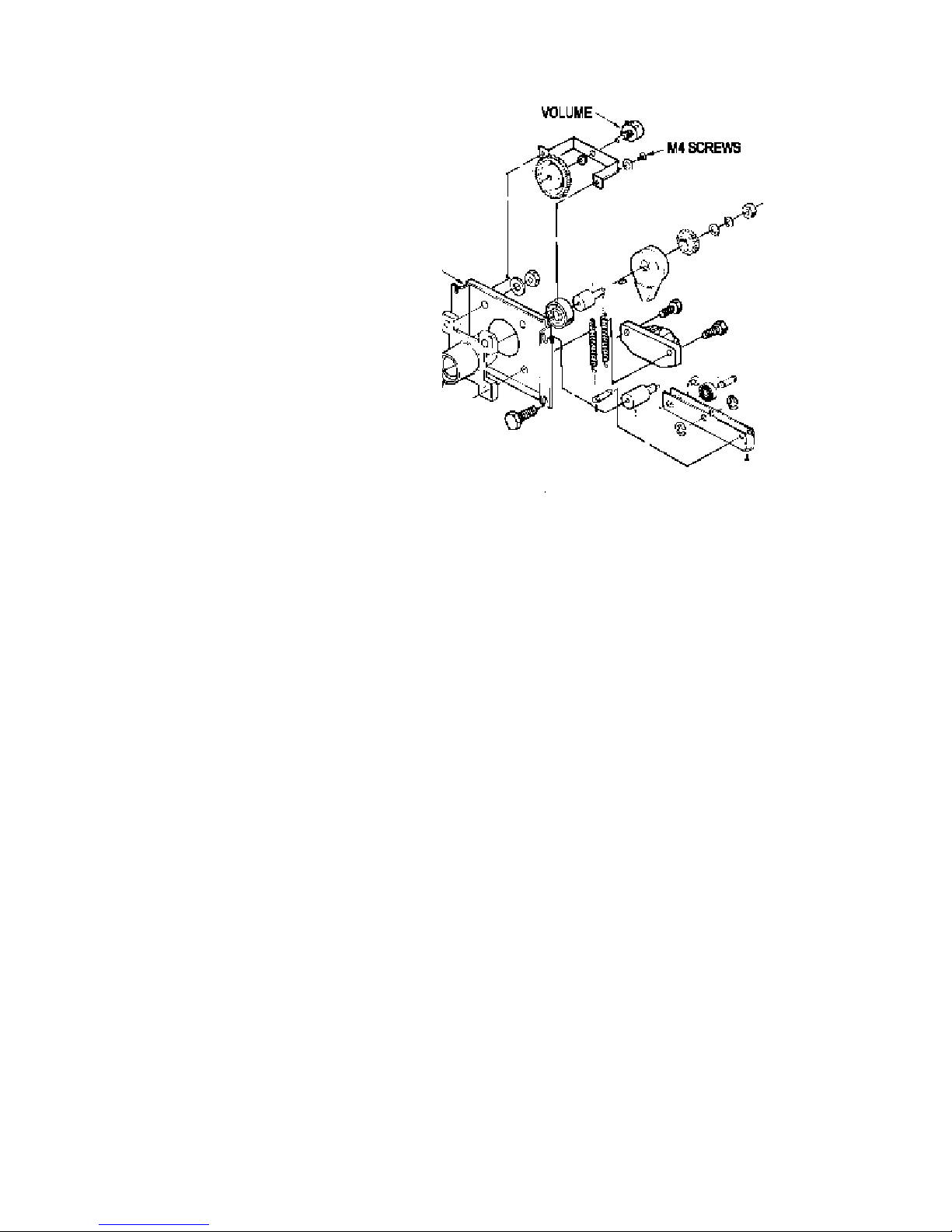
1. Loosen the two screws and adjust
the gear mesh by moving the VR
Bracket.
2. Adjust to an appropriate setting by
securing the steering wheel in the
straight ahead position.
3. After adjustment, check the volume
setting as described in Section 5.3.5.
If necessary, repeat steps 3 & 4 until
the volume value is within allowable
limits (±3H)
HOW TO REPLACE
1. Disconnect the Volume Connector.
2. Take out the two screws and remove the Volume together with the VR Bracket.
3. After replacing the Volume, engage the gears at the angle shown and fix the VR Bracket.
Close the Control Panel and replace the three tamperproof screws before turning power ON and setting the
Volume value in the TEST MODE.
29
 Loading...