

Page 1
)
R
)
)
)
y)
Page 1 of 1Daytona LE Owner's Manual: Table of Contents
DAYTONA LE
TABLE OF CONTENTS
INTRODUCTION OF THE OWNER'S MANUAL 1
GENERAL PRECAUTIONS 2
SPECIFICATIONS 3
INSTALLATION AND HARDWARE 4
CONNECTING THE CABINETS 5
SECURING IN PLACE (LEG ADJUSTERS
6
ASSEMBLY CHECKS 7-21
EXPLANATION OF TEST AND DATA DISPLAY 8
SWITCH UNIT 9
TEST MODE 10
BOOKKEEPING 11
GAME SYSTEM 12
COIN ASSIGNMENTS 13
INPUT TEST 14
OUTPUT TEST 15
CRT TEST 16
DRIVE BOARD TEST 17
SOUND TEST 18
TGP TEST 19
MEMORY TEST 20
BACK UP RAM CLEAR 21
COIN SELECTO
CAUTIONS AND WARNINGS CONCERNING SAFETY FOR HANDLING THE
MONITORS
22
23
PERIODIC INSPECTION TABLE 24
TROUBLESHOOTING 25
GAME BOARD 26
DESIGN RELATED PARTS 27
PARTS IDENTIFICATION 28
ASSY VIRTUAL BUTTON (DYN0-1290
28
ASSY SPEAKER (130-5156) 29
ASSY HANDLE MECHA (DYN-1250
ASSY ACCEL & BRAKE (DYN-1300
30
31
ADDITIONAL PARTS 32
WIRING DIAGRAM (refer to Daytona Twin diagram - reference onl
XXX
7/12/2005http://www.sauservice.com/manuals/Daytona%20Folder/DaytonaLE/Daytona%20LE%20...
Page 2

p
y
Page 1 of 1Introduction of the Owner's Manual
[Table of Contents] [Next Page]
INTRODUCTION OF THE OWNERS MANUAL
SEGA ENTERPRISES, LTD., has for more than 30 years been supplying various innovative and
opular amusement products to the world market. This Owners Manual is intended to provide detailed
descriptions together with all the necessary installation, game settings and parts ordering information
related to the DAYTONA USA SPECIAL EDITION, a new SEGA product.
This manual is intended for those who have knowledge of electricity and technical expertise, especially
in ICs, CRTs, microprocessors, and circuit boards. Read this manual carefully to acquire sufficient
knowledge before working on the machine. Should there be a malfunction, non-technical personnel
should under no circumstances touch the interior system. Should the need arise, contact our main office,
or the closest branch office listed below.
SEGA ENTERPRISES, INC. (USA)
Customer Service
45133 Industrial Drive
Fremont, CA 94538
Phone 415-802-1750
Fax 415-802-1754
7:30 am - 4:00 pm, Pacific Standard Time
Monda
thru Friday
7/12/2005http://www.sauservice.com/manuals/Daytona%20Folder/DaytonaLE/Daytona%20LE%20...
Page 3

g
Page 1 of 3General Precautions
[Table of Contents] [Previous Page] [Next Page]
GENERAL PRECAUTIONS
Follow Instructions: All operating and use instructions should be followed.
Attachments: Do not use attachments not recommended by the product manufacturer as they may cause
hazards.
Accessories: Do not place this product on an unstable cart, stand, tripod, bracket, or table. The product
may fall, causing serious injury to a child or adult, and serious damage to the product. Use only with a
cart, stand, tripod, bracket, or table recommended by the manufacturer, or sold with the product. Any
mounting of the product should follow the manufacturer's instructions, and should use only mounting
accessories recommended by the manufacturer.
Moving the Product: This product should be moved with care. Quick stops, excessive force, and uneven
surfaces may cause the product to overturn.
Ventilation: Slots and openings in the cabinet are provided for ventilation, to ensure reliable operation of
the product and to protect it from overheating; these openings must not be blocked or covered. The
openings should never be blocked by placing the product in a built-in installation such as a bookcase or
rack unless proper ventilation is provided or the manufacturer's instructions have been adhered to.
Power Sources: This product should be operated only from the type of power source indicated on the
marking label. If you are not sure of the type of power supply to your location, consult your local power
company. For products intended to operate from battery power or other sources, refer to the operating
instructions.
Grounding or Polarization: This product is equipped with a three-wire grounding-type plug, a plug
having a third (grounding) pin. This plug will only fit into a grounding-type power outlet. This is a
safety feature. If you are unable to insert the plug into the outlet, contact your electrician to replace your
obsolete outlet. Do not defeat the safety purpose of the grounding-type plug.
Power Cord Protection: Power-supply cords should be routed so that they are not likely to be walked on
or pinched by items placed upon or against them, paying particular attention to cords at plugs,
convenience receptacles, and the point where they exit from the product.
Overloading: Do not overload wall outlets, extension cords, or integral convenience receptacles as this
can result in a risk of fire or electric shock.
Object and Liquid Entry: Never push objects of any kind into this product through openings as they may
touch dangerous voltage points or short-out parts that could result in a fire or electric shock. Never spill
liquid of any kind on the product.
Servicin
: Do not attempt to service this product yourself as opening or removing covers may expose
7/12/2005http://www.sauservice.com/manuals/Daytona%20Folder/DaytonaLE/Daytona%20LE%20...
Page 4

p
p
p
Page 2 of 3General Precautions
you to dangerous voltage or other hazards. Refer all servicing to qualified service personnel.
Damage Requiring Service: Unplug this product from the wall outlet and refer servicing to qualified
service personnel under the following conditions:
a) If the power cord or plug is damaged;
b) If liquid has been spilled, or objects have fallen into the product;
c) If the product has been exposed to rain or water;
d) If the product does not operate normally when following the operating instructions. Adjust only
those controls that are explained in the operating instructions. An improper adjustment of other controls
may result in damage and will often require extensive work by a qualified technician to restore the
roduct to its normal operation;
e) If the product has been dropped or damaged in any way;
f) When the product exhibits a distinct change in performance; this indicates a need for service.
Replacement Parts: When replacement parts are required, be sure the service technician has used
replacements parts specified by the manufacturer or that have the same characteristics as the original
art. Unauthorized substitutions may result in fire, electric shock, or other hazards.
Safety Check: Upon completion of any service or repairs to this product, ask the service technician to
erform safety checks to determine that the product is in proper operating condition.
Heat: The product should be situated away from heat sources such as radiators, heat registers, stoves, or
other products (including amplifiers) that produce heat.
Cleaning: When cleaning the monitor glass, use water or glass cleaner and a soft cloth. Do not apply
chemicals such as benzine, thinner, etc.
Location: This an indoor game machine, DO NOT install it outside. To ensure proper usage, avoid
installing indoors in the places mentioned below:
· Places subject to rain/water leakage, or condensation due to humidity;
· In close proximity to a potential wet area;
· Locations receiving direct sunlight;
· Places close to heating units or hot air;
· In the vicinity of highly inflammable/volatile chemicals or hazardous matter;
· On sloped surfaces;
· In the vicinity of emergency response facilities such as fire exits and fire extinguishers;
7/12/2005http://www.sauservice.com/manuals/Daytona%20Folder/DaytonaLE/Daytona%20LE%20...
Page 5
· Places subject to any type of violent impact;
· Dusty places.
Installation Precautions
· Verify the amperage of the branch circuit outlet before plugging in the power plug. Do not
overload the circuit.
· Avoid using an extension cord. If one is required, use an extension cord of type SJT, 16/3 AWG
rated min. 120 VAC, 7A.
· Moving this unit requires a minimum clearance (of doors, etc.) of 32" (W) by 77" (H).
· For the operation of this machine, secure a minimum area of 32" (W) by 42"(D).
Page 3 of 3General Precautions
Regulatory Approvals
This game has been tested and found to comply with the Federal Communications Commission Rules.
This device complies with Part 15 of the FCC Rules. Operation is subject to the following two
conditions: (1) This device may not cause harmful interference, and (2) this device must accept any
interference received, including interference that may cause undesired operation.
This game has been tested and listed by Underwriters Laboratories, Inc., to ANSI/UL22.
7/12/2005http://www.sauservice.com/manuals/Daytona%20Folder/DaytonaLE/Daytona%20LE%20...
Page 6
SPECIFICATIONS
S
y
y
[Table of Contents] [Previous Page] [Next Page]
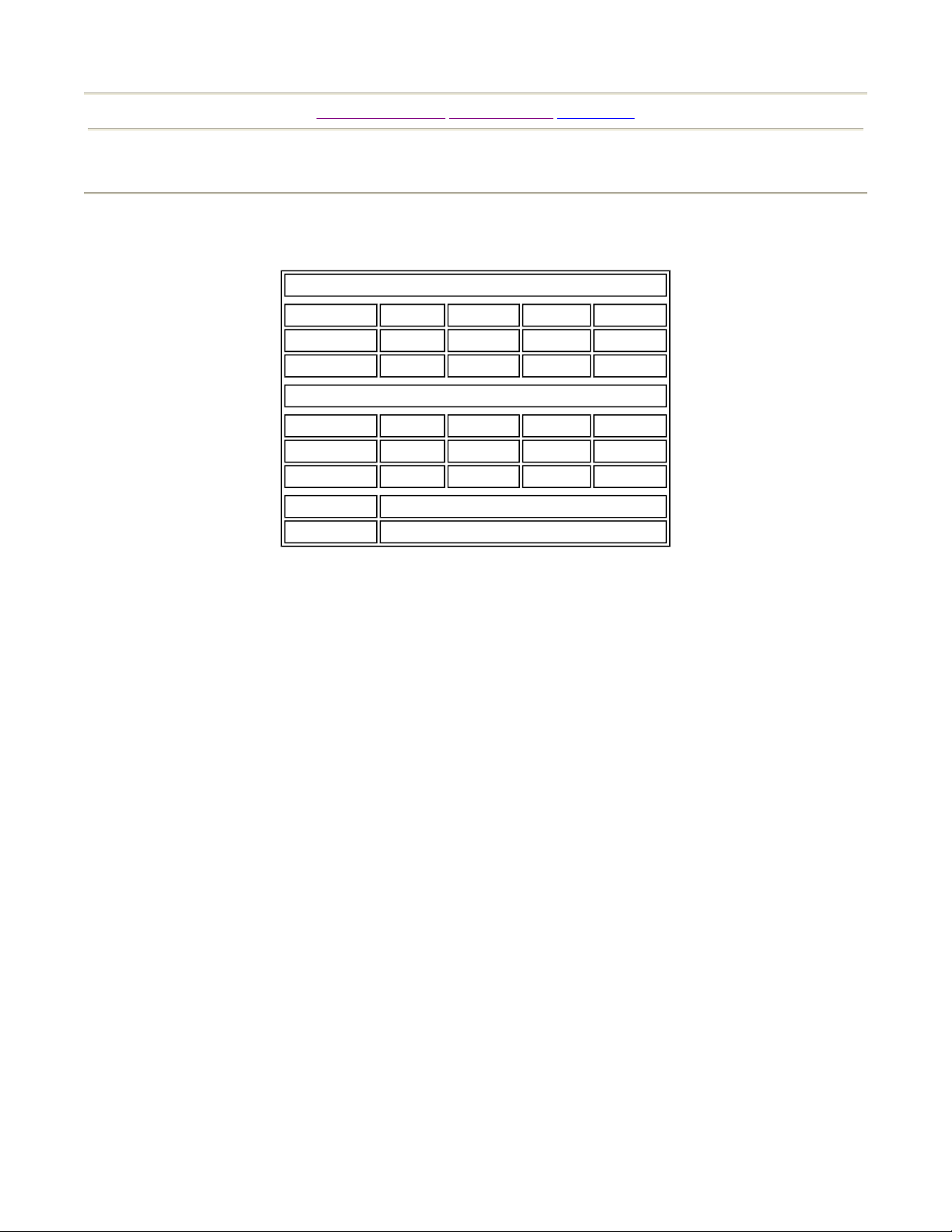
eat Assembl
Width
Crated
Assembled
Monitor Assembl
Crated
Assembled
24.25" 42.5" 47" 140 lbs
21.25" 38" 44.5" 120 lbs
Width Length Height Weight
35.5" 43.5" 73" 450 lbs
31.75" 39" 70" 430 lbs
Length Height Weight
Page 1 of 1Specifications
Monitor
Power
26" Wells Gardner Monitor 25K5191
AC 345W 3A
7/12/2005http://www.sauservice.com/manuals/Daytona%20Folder/DaytonaLE/Daytona%20LE%20...
Page 7
[Table of Contents] [Previous Page] [Next Page]
N
r
)
)
INSTALLATION AND HARDWARE
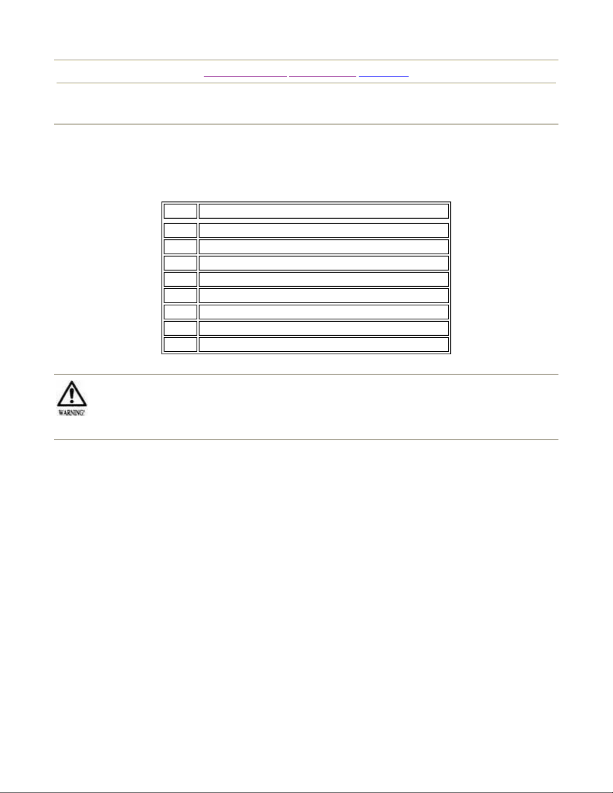
When transporting the machine, make sure that the following parts are supplied.
QTY. DESCRIPTION
2 Key, Coin Mech Doo
2 Key, Cash Box (Behind Coin Mech Door
2 Key, Rear Service Door (Behind Coin Mech Door
1 Owners manual, Daytona
1 Fiber Optic Cable
1 Wrench, T-20 torx tamperproof
1 Wrench, T-27 torx tamperproof
1 Wrench, T-15 torx tamperproof
Page 1 of 1Installation and Hardware
Perform the assembly work by following the procedure stated herein. Failure to comply with
these instructions can result in electric shock.
When assembling, be sure that two or more persons are available to perform the work. In some
cases, attempting the assembling work alone can result in injury or damage to the game and its parts.
When carrying out the installation instructions, follow the sequence outlined below.
1. Connect the cabinets.
2. Secure in place
3. Connect power supply
4. Perform the assembly check
ote that for installation work, a master key and other hardware are required. Refer to the preceding list
of installation items.
7/12/2005http://www.sauservice.com/manuals/Daytona%20Folder/DaytonaLE/Daytona%20LE%20...
Page 8

p
p
Page 1 of 1Connecting the Cabinets
[Table of Contents] [Previous Page] [Next Page]
CONNECTING THE CABINETS
The brackets for connecting the seat and monitor cabinets are shipped attached to the game. All
hardware is attached to the brackets at the time of shipping.
To assemble the two cabinets, remove all retaining hardware and move the cabinets to their installation
osition.
Bring the seat and monitor cabinets together, at the installation position.
Align the connection bracket on the seat and monitor cabinets and fasten securely with the hardware
rovided.
To move the game, first disassemble the connecting bracket. Do not attempt to move the game with the
cabinets connected. To do so can cause damage to the cabinets and bracket assembly.
7/12/2005http://www.sauservice.com/manuals/Daytona%20Folder/DaytonaLE/Daytona%20LE%20...
Page 9
Page 1 of 1Securing in Place (Leg Adjusters
)
[Table of Contents] [Previous Page] [Next Page]
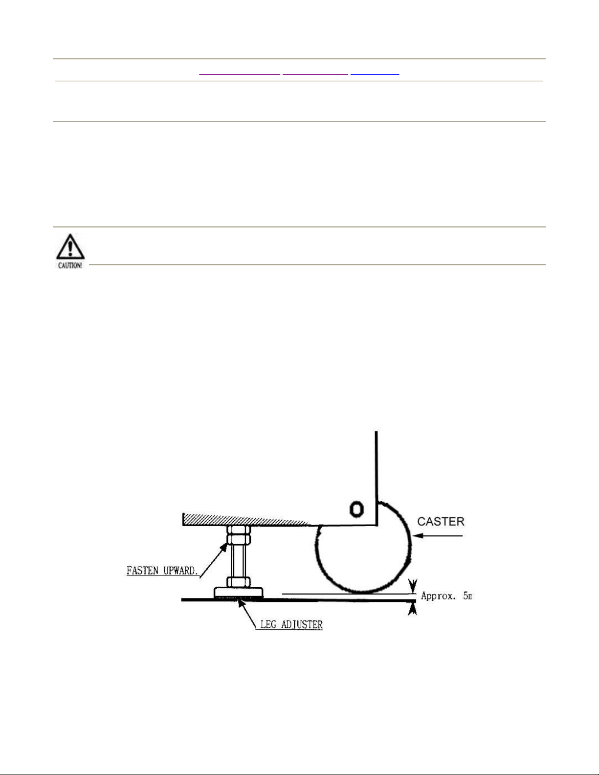
SECURING IN PLACE (LEG ADJUSTERS)
This machine has 2 casters and 8 leg adjusters. When the installation position is determined, cause the
leg adjusters to come into contact with the floor, and make adjustments so that the casters are raised
approximately 5 mm. above the floor, and the machine is level.
Make sure that all of the leg adjusters are in contact with the floor. If they are not, the cabinet
can move causing an accident.
Move the machine to the installation position. When installing the machine against or close to a wall, be
sure to secure a passage space to enable the player to take a ride in the machine.
Have the leg adjusters make contact with the floor. To keep the machine level, adjust the height of the
leg adjuster upward using a wrench.
After making adjustments, fasten the leg adjuster nut upward and secure the height of the leg adjuster.
7/12/2005http://www.sauservice.com/manuals/Daytona%20Folder/DaytonaLE/Daytona%20LE%20...
Page 10
ASSEMBLY CHECKS
Page 1 of 2Assembly Checks
[Table of Contents] [Previous Page] [Next Page]
In the Test mode, ascertain that the assembly has been made
correctly and IC Board is satisfactory.
In the test mode, perform the following tests:
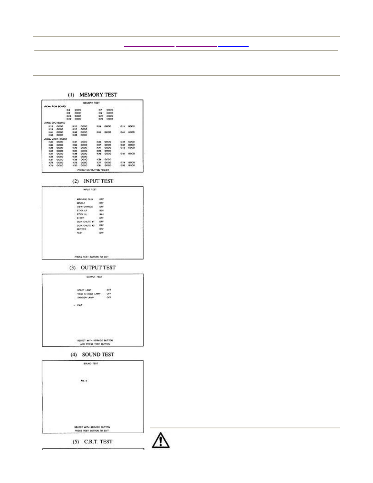
1. Memory Test
Selecting the Memory Test on the test mode menu screen causes
the on-board memory to be tested automatically. The game
board is satisfactory if the display beside each IC number shows
GOOD.
2. Input Test
Selecting the Input Test on the test mode menu screen causes the
screen (on which each switch is tested) to be displayed. Press
each switch. For the coin switch test, insert a coin from the coin
inlet with the coin chute door open. If the display beside each
switch indicates ON, the switch and wiring connections are
satisfactory.
3. Output Test
In the Output Test mode, carry out the lamp test to ascertain that
each lamp lights up satisfactorily.
4. Sound Test
In the Test mode, selecting Sound Test causes the screen (on
which sound-related board and wiring connections are tested) to
be displayed.
Be sure to check if the sound is satisfactorily emitted from each
speaker and the sound volume is appropriate.
5. C.R.T. Test
In the Test mode menu, selecting C.R.T. Test allows the screen
(on which the monitor is tested) to be displayed. Although the
monitor adjustments have been made at the time of shipment
from the factory, color deviation, etc. may occur due to the
effect caused by geomagnetism, the location building's steel
frames and other game machines on the periphery. By watching
the test mode screen, decide whether an adjustment is needed. If
it is necessary, adjust the monitor by referring to the Monitor
Adjustments section.
The weight of the machine is approximately 560 lbs.
When moving the machine on the floor, be sure to retract
7/12/2005http://www.sauservice.com/manuals/Daytona%20Folder/DaytonaLE/Daytona%20LE%20...
Page 11

Page 2 of 2Assembly Checks
the leg adjusters so that the casters make contact with the
floor. Attempting to push the machine with leg adjusters extended can cause the machine to fall, causing
injury and damage.
7/12/2005http://www.sauservice.com/manuals/Daytona%20Folder/DaytonaLE/Daytona%20LE%20...
Page 12
j
j
Page 1 of 1Explanation of Test and Data Displa
y
[Table of Contents] [Previous Page] [Next Page]
EXPLANATION OF TEST AND DATA DISPLAY
By operating the switch unit, periodically perform the tests and data check. When initially installing the
machine, collecting cash, or when the machine does not function properly, perform checks in
accordance with this section.
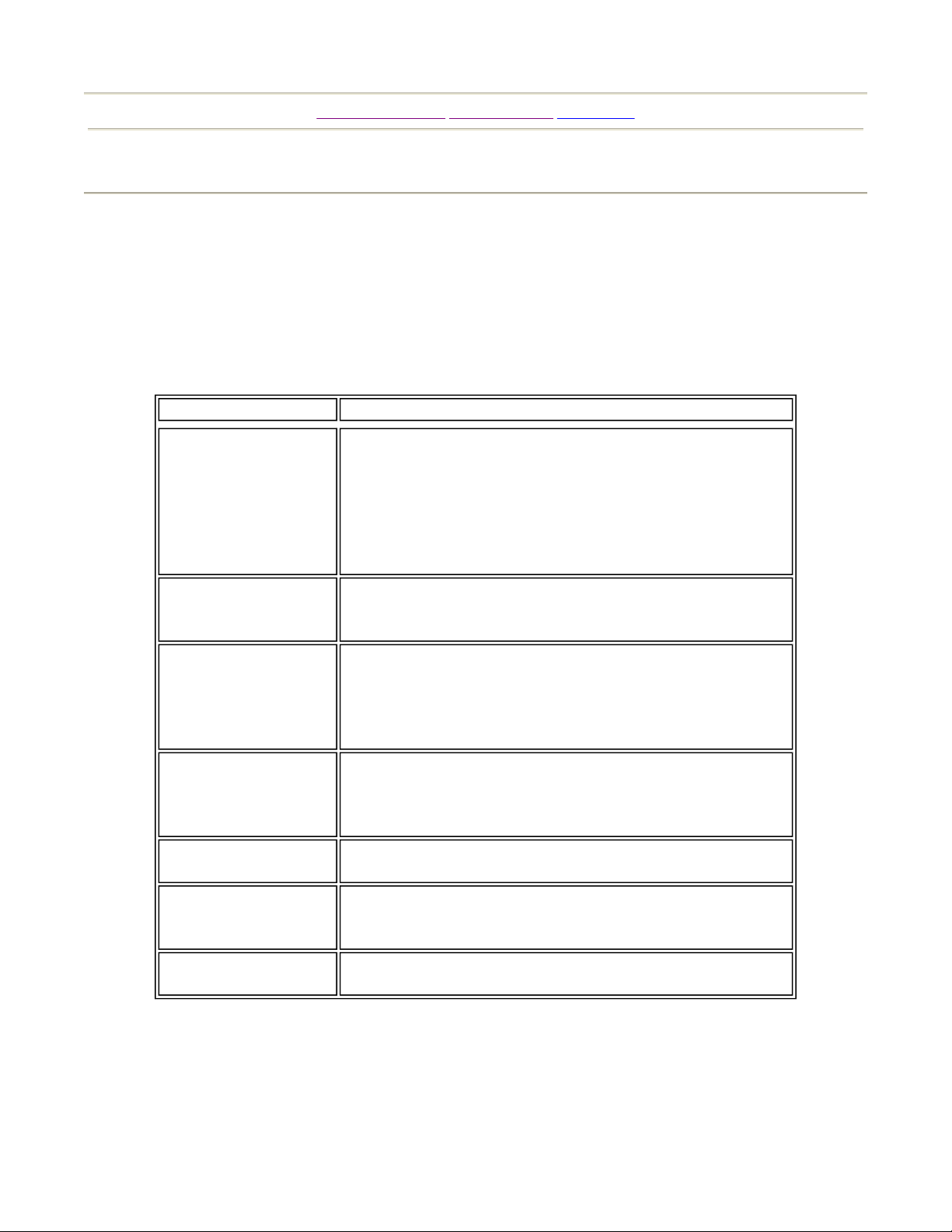
The following test modes should be utilized when applicable.
Items
Installation of machine
Memory
Monthly Servicing
Control System
Monitor
IC Board
Data Check
Description
When the machine is installed, perform the following:
1. Check to see that each setting is per standard setting
made at the time of shipment.
2. In the INPUT TEST mode, check each SW and VR.
3. In the OUTPUT TEST mode, check each of the lamps.
4. In the MEMORY test mode, check each of the IC's on the
PC board.
Choose MEMORY test in the MENU mode to allow the
memory test to be performed. In this test, PROGRAM
RAMs, ROMs, and ICs onthe PCboard are checked.
Monthly, perform the following:
1. MEMORY TEST.
2. Ascertain each setting.
3. In the INPUT test mode, test the CONTROL device.
4. In the OUTPUT test mode, check each of the lamps.
In the INPUT test mode, check each SW and VR.
Adjust or replace each SW or VR.
If the problem cannot yet be solved, check the
CONTROL's moves.
In the MONITOR ADJUSTMENT mode, check to see
if the MONITOR ad
ustment is correct.
1. MEMORY TEST
2. In the SOUND test mode, check the sound related
ROMs.
Check such data as game play and histogram to
ust the difficulty level, etc.
ad
7/12/2005http://www.sauservice.com/manuals/Daytona%20Folder/DaytonaLE/Daytona%20LE%20...
Page 13
Page 1 of 1Switch Unit
[Table of Contents] [Previous Page] [Next Page]
SWITCH UNIT
The tests or data check are performed when initially installing the machine, when collecting cash, or
when the machine does not function correctly. The switch unit is used to access the various tests and
modes listed below. Refer to the explanations given in this section to perform each type of test.
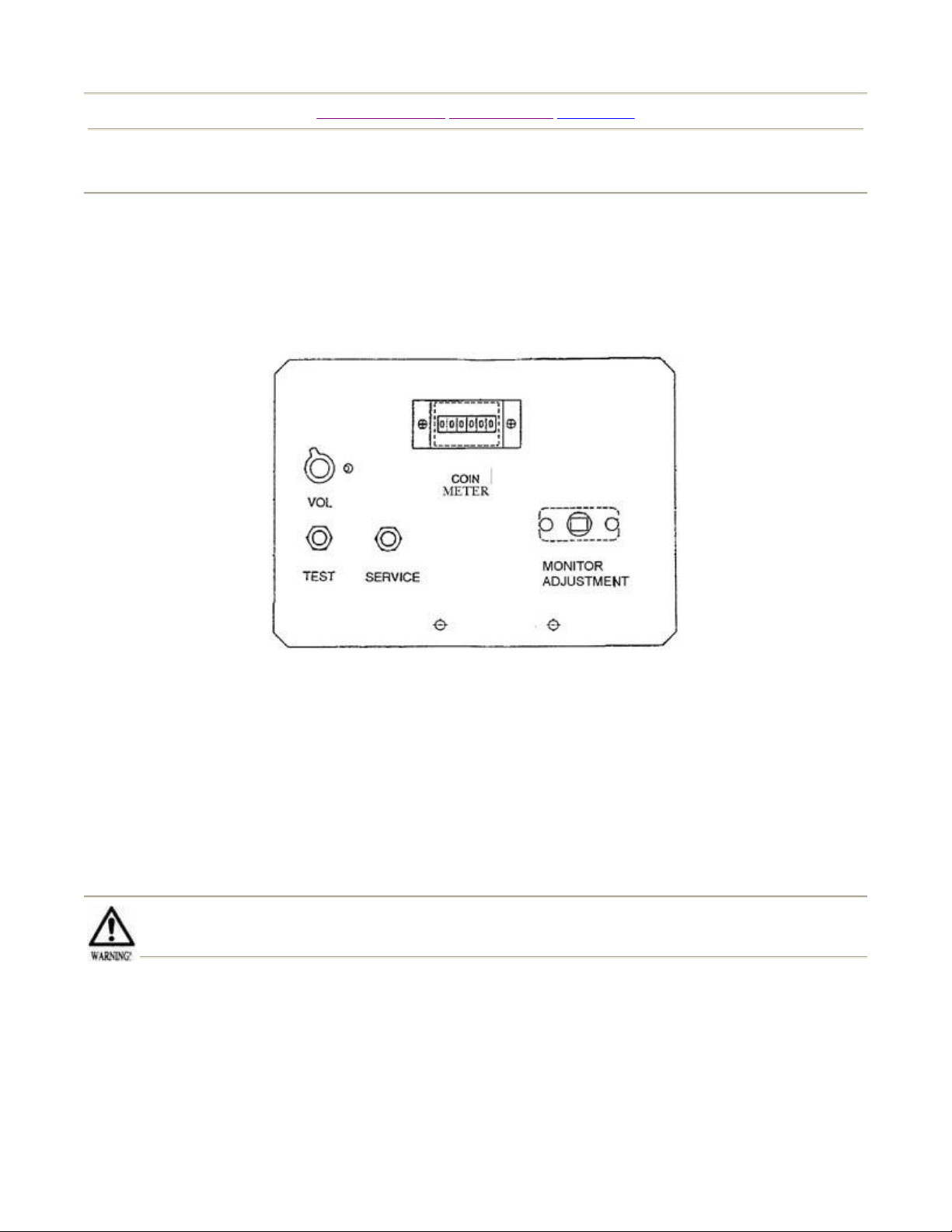
Open the coin chute door, and the switch unit will appear. The functioning of each switch is as follows:
Test Button
Service Button
Sound Volume
Monitor Adjustment
- For handling of the Test Button, refer to the following pages.
- Gives credits without registering on the coin meter.
- Adjusts the volume of the monitor's right-hand side and left- hand side speakers.
- Eliminates color unevenness from the screen.
Do not touch places other than those specified. Touching places not specified can cause an
electric shock or short circuit accident.
7/12/2005http://www.sauservice.com/manuals/Daytona%20Folder/DaytonaLE/Daytona%20LE%20...
Page 14
Page 1 of 1Test Mode
[Table of Contents] [Previous Page] [Next Page]
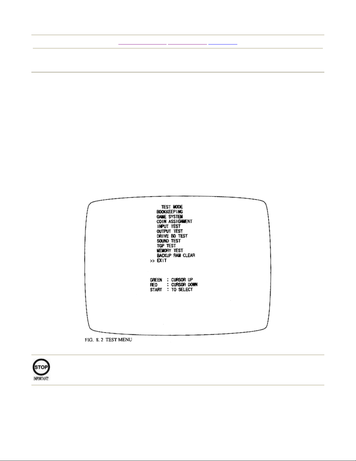
TEST MODE
The Test Menu allows the functioning of each part of the Cabinet to be checked, the monitor to be
adjusted, and the coins and game related various settings to be performed.
· Press the Test Button to cause the following Test Menu to be displayed on the monitor.
· Press the Service Button until the arrow --> is moved to the desired item to make a selection
· Bring the arrow --> to the desired item and press the Test Button to enter the selected item's test.
· Choosing EXIT and pressing the Test Button will finish the test mode, and the game mode
returns on the screen after network checking.
When changes are made in the Game Assignments, Coin Assignments and Volume settings, be
sure to exit from the test mode to return to game mode.
If the power is turned off in test mode, the setting can not be re-written.
7/12/2005http://www.sauservice.com/manuals/Daytona%20Folder/DaytonaLE/Daytona%20LE%20...
Page 15
Page 1 of 2Bookkeepin
g
[Table of Contents] [Previous Page] [Next Page]
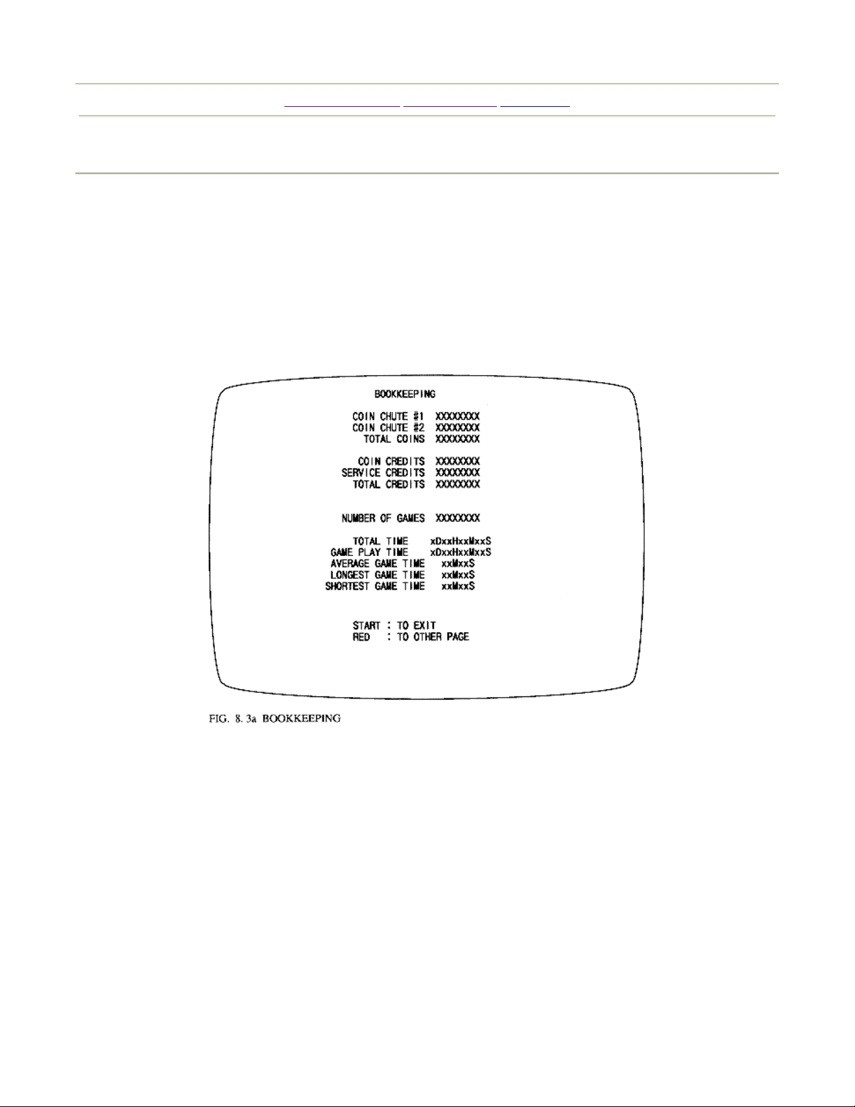
BOOKKEEPING
Selecting bookkeeping in the menu mode causes the bookkeeping data up to the present to be displayed.
Press the test button or start button to return to the menu screen.
Press the VR1 red button to proceed to the next page.
COIN CHUTE # - Number of coins put in. As seen from the front of the cabinet, the right hand side is
#1 and the left hand side is #2.
TOTAL COINS - Total number of activations of coin chutes.
COIN CREDITS - Number of credits registered by inserting coins.
SERVICE CREDITS - Credits registered by service switch.
TOTAL CREDITS - Total number of credits (coin credits+service credits).
TOTAL TIME - The total energized time.
7/12/2005http://www.sauservice.com/manuals/Daytona%20Folder/DaytonaLE/Daytona%20LE%20...
Page 16
Page 2 of 2Bookkeepin
g
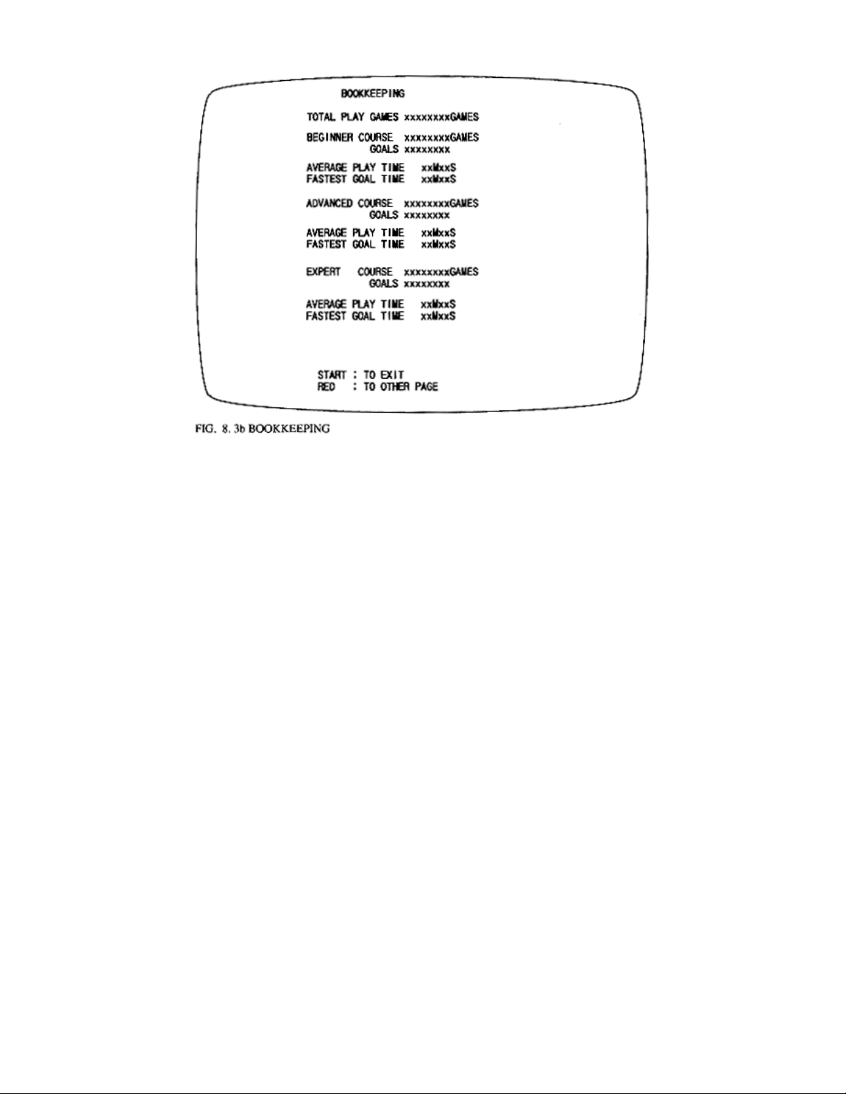
BEGINNER COURSE - Beginner course's game play frequency.
ADVANCED COURSE - Advanced course's game play frequency.
EXPERT COURSE - Expert course's game play frequency.
GOALS - Total number of goals each course.
Press the Test SW or Start button to return to the menu mode screen.
Press VR1 red button to proceed to the other page.
7/12/2005http://www.sauservice.com/manuals/Daytona%20Folder/DaytonaLE/Daytona%20LE%20...
Page 17

p
Page 1 of 2Game System
[Table of Contents] [Previous Page] [Next Page]
GAME SYSTEM
Selecting the GAME SYSTEM (See Fig. 11) in the menu mode causes the present game settings to be
displayed and allows setting changes to be made. Each GAME SYSTEM setting is explained below.
LINK ID: Standard setting is "SINGLE". For linked units, set one to "MASTER" and the rest of the
seats to "SLAVE". The game setting and coin setting, etc. of the MASTER seat apply to all SLAVE
seats. Changes made to SLAVE seats are not effective.
CAR NUMBER: For linked play between 2 or more machines, the machines are numbered in sequential
order: No. 1, No. 2, No. 3, ... No. 8. Numbering is done starting from the left, facing the monitor screen.
If the same number is used for 2 or more cabinets or if cabinets are numbered in an incorrect sequence,
the on-screen display may be confused.
CABINET: Setting of cabinet type. Set to "STAND ALONE" for this machine.
COUNTRY: Message language. Choices are "USA", "EXPORT", and "JPN".
DIFFICULTY: The game difficulty is classified into 4 different categories from "EASY" to
"HARDEST". The standard setting is "NORMAL".
ADVERTISE SND: Set to "OFF" to have machine silent during standby. Standard setting is "OFF."
GAME MODE: Selection of lap count ranges for BEGINNER, ADVANCED, and EXPERT courses.
Allows la
count to be changed for specific attraction event purposes. Ranges are: "NORMAL" (8, 4, 2
7/12/2005http://www.sauservice.com/manuals/Daytona%20Folder/DaytonaLE/Daytona%20LE%20...
Page 18

b
Page 2 of 2Game System
laps), "GRAND PRIX" (20, 10, 5 laps), and "ENDURANCE" (80, 40, 20 laps).
SETTING CHANGE PROCEDURE
1. Press the SERVICE switch or VR1 (red) OR VR2 (green) to move the arrow (>>) to the desired item.
2. Choose the desired setting change item by using one of: VR2 (blue), VR3 (yellow), the TEST switch,
or the START button.
3. To return to the MENU mode, move the arrow to EXIT and press the TEST switch or the START
utton.
7/12/2005http://www.sauservice.com/manuals/Daytona%20Folder/DaytonaLE/Daytona%20LE%20...
Page 19

p
Page 1 of 3Coin Assignments
[Table of Contents] [Previous Page] [Next Page]
COIN ASSIGNMENTS
This mode permits you to set the start number of credits, as well as the basic numbers of coins and
credits. This mode expresses "how many coins correspond to how many credits".
Setting change is not effective until Exiting. Be sure to Press test to Exit after setting change.
Credit to Start
Credit to Continue
Coin/Credit Setting
- Sets the number of credits required when starting the game.
- This sets the number of credits required to continue game.
- How many coins correspond to how many credits. In this machine, selection as
er the adjacent chart is possible.
Manual Setting
- Allows for finer settings. See chart.
1. Press the Service button or Shift button to bring the arrow to the desired change item.
7/12/2005http://www.sauservice.com/manuals/Daytona%20Folder/DaytonaLE/Daytona%20LE%20...
Page 20

Page 2 of 3Coin Assignments
2. Press the Test button or the Start button to select the setting change item.
3. Move the arrow to Exit and press the Test button or the Start button to return the menu mode to the
screen.
COIN/CREDIT SETTING (COIN CHUTE COMMON TYPE)
NAME OF
SETTING
SETTING #1 1 COIN, 1 CREDIT 1 COIN, 1 CREDIT
SETTING #2 1 COIN, 2 CREDITS 1 COIN, 1 CREDIT
SETTING #3 1 COIN, 3 CREDITS 1 COIN, 1 CREDIT
SETTING #4 1 COIN , 4 CREDITS 1 COIN, 1 CREDIT
SETTING #5 1 COIN, 5 CREDITS 1 COIN, 1 CREDIT
SETTING #6 1 COIN, 2 CREDITS 1 COIN, 2 CREDITS
SETTING #7 1 COIN, 5 CREDITS 1 COIN, 2 CREDITS
SETTING #8 1 COIN, 3 CREDITS 1 COIN, 3 CREDITS
SETTING #9 1 COIN, 4 CREDITS 1 COIN, 4 CREDITS
SETTING #10 1 COIN, 5 CREDITS 1 COIN, 5 CREDITS
SETTING #11 1 COIN, 6 CREDITS 1 COIN, 6 CREDITS
SETTING #12 2 COINS, 1 CREDIT 2 COINS, 1 CREDIT
SETTING #13 1 COIN, 1 CREDIT 2 COIN, 1 CREDIT
SETTING #14 1 COIN, 2 CREDITS 2 COIN, 1 CREDIT
SETTING #15
SETTING #16 1 COIN, 3 CREDITS
SETTING #17 3 COINS, 1 CREDIT 3 COINS, 1 CREDIT
SETTING #18 4 COINS, 1 CREDIT 4 COINS, 1 CREDIT
SETTING #19
SETTING #20 1 COIN, 5 CREDITS
SETTING #21 5 COINS, 1 CREDIT 5 COINS, 1 CREDIT
SETTING #22 1 COIN, 2 CREDITS
SETTING #23
SETTING #24 1 COIN, 3 CREDITS
SETTING #25
FUNCTIONING OF COIN
CHUTE #1
1 COIN, 1 CREDIT
2 COINS, 3 CREDITS
1 COIN, 1 CREDIT
2 COINS, 2 CREDITS
3 COINS, 3 CREDITS
4 COINS, 5 CREDITS
2 COIN, 1 CREDIT
4 COIN, 2 CREDITS
5 COIN, 3 CREDITS
1 COIN, 1 CREDIT
2 COINS, 2 CREDITS
3 COINS, 3 CREDITS
4 COINS, 4 CREDITS
FUNCTIONING OF COIN
CHUTE #2
1 COIN, 1 CREDIT
2 COINS, 3 CREDITS
1 COIN, 1 CREDIT
2 COINS, 3 CREDITS
1 COIN, 1 CREDIT
2 COINS, 2 CREDITS
3 COINS, 3 CREDITS
4 COINS, 5 CREDITS
1 COIN, 1 CREDIT
2 COINS, 2 CREDITS
3 COINS, 3 CREDITS
4 COINS, 5 CREDITS
1 COIN, 1 CREDIT
5 COINS, 2 CREDITS
2 COIN, 1 CREDIT
4 COIN, 2 CREDITS
5 COIN, 3 CREDITS
1 COIN, 1 CREDIT
4 COIN, 2 CREDITS
5 COIN, 3 CREDITS
1 COIN, 1 CREDIT
2 COINS, 2 CREDITS
3 COINS, 3 CREDITS
4 COINS, 4 CREDITS
7/12/2005http://www.sauservice.com/manuals/Daytona%20Folder/DaytonaLE/Daytona%20LE%20...
Page 21

5 COINS, 6 CREDITS 5 COINS, 6 CREDITS
1 COIN, 1 CREDIT
2 COINS, 2 CREDITS
SETTING #26 1 COIN, 6 CREDITS
SETTING #27 FREE PLAY FREE PLAY
3 COINS, 3 CREDITS
4 COINS, 4 CREDITS
5 COINS, 6 CREDITS
Page 3 of 3Coin Assignments
7/12/2005http://www.sauservice.com/manuals/Daytona%20Folder/DaytonaLE/Daytona%20LE%20...
Page 22

Page 1 of 1Input Test
[Table of Contents] [Previous Page] [Next Page]
INPUT TEST
When Input Test is selected, the monitor will show the following, allowing you to watch the status of
each switch. On this screen, periodically check the status of each switch.
· By pressing each switch, if the display on the right-hand side of the name of each switch changes
to ON from OFF, the switch and the wiring connections are satisfactory. When the Controller (Lever) is
operated in the direction of the arrow, the right-hand side indication of the Switch name becomes ON.
· To check Coin Chute #1 and Coin Chute #2 Coin Switches, open the Coin Chute Door and insert
coin(s) into the slot.
· To return to the Menu mode, press the Test button.
7/12/2005http://www.sauservice.com/manuals/Daytona%20Folder/DaytonaLE/Daytona%20LE%20...
Page 23

Page 1 of 1Output Test
[Table of Contents] [Previous Page] [Next Page]
OUTPUT TEST
Selecting Output Test allows the status of each lamp to be viewed. Periodically check the status of each
lamp on this screen.
<-- Repeatedly displays sequentially in order of start lamp, view change and danger lamp. At this time
lamp tests are performed in the manner corresponding to the item displayed.
This game does not have 7-SEG LED. During the display of 7-SEG, only the Start button flashes.
· While this screen is displayed, the Start button continues to flash.
· Press the Test button to return to the menu mode.
7/12/2005http://www.sauservice.com/manuals/Daytona%20Folder/DaytonaLE/Daytona%20LE%20...
Page 24

Page 1 of 2CRT Test
[Table of Contents] [Previous Page] [Next Page]
CRT TEST
Choose CRT Test to display the screen on which the Monitor adjustment is checked. By watching the
screen, periodically check if adjustments are needed or not. For adjustment, refer to the Section of
Monitor Adjustment stated herein.
In above figure, check the Monitor's color adjustment. Perform color adjustment by watching this
screen.
The color bar of 4 colors, i.e. red, green, blue and white is darkest at the left end and becomes brighter
towards the right end.
Pressing the Test button will have the following crosshatch screen appear.
7/12/2005http://www.sauservice.com/manuals/Daytona%20Folder/DaytonaLE/Daytona%20LE%20...
Page 25

Page 2 of 2CRT Test
In this figure, check the Monitor size and position adjustment by watching the screen.
Adjust the Monitor in the manner so that the crosshatch lines do not go beyond the screen. Adjust the
Monitor to ensure that crosshatch lines do not have distortions.
Press the Test button to return to the menu mode.
7/12/2005http://www.sauservice.com/manuals/Daytona%20Folder/DaytonaLE/Daytona%20LE%20...
Page 26

g
Page 1 of 3Drive Board Test
[Table of Contents] [Previous Page] [Next Page]
DRIVE BOARD TEST
Choosing Drive Board Test allows the reaction mechanism of the steering wheel to be checked. Also,
this enables the VR value for the steering wheel's drive board and the settings of the dip switches on the
drive board to be checked.
Bring the arrow -> to the desired item by using the service switch or VR1 (red) or VR4 (green). The
steering wheel functions to the setting selected by the arrow. Pressing VR2 (blue) or VR3 (yellow)
allows the force transmitted to the steering wheel to increase or decrease.
SPRING - Status in which the motor and clutch are not activated. Centering of the handle is caused by
only the spring inside the handle mechanism.
CLUTCH - Status in which the clutch is activated. The handle is fixed.
CENTERING - Status in which the handle returns to the center position by itself.
UNCENTERING - Status in which the handle is caused not to be in the center.
ROLL LEFT - Status in which the handle is rotated in the left hand direction.
ROLL RIGHT - Status in which the handle is rotated in the ri
ht hand direction.
7/12/2005http://www.sauservice.com/manuals/Daytona%20Folder/DaytonaLE/Daytona%20LE%20...
Page 27

N
Page 2 of 3Drive Board Test
EXIT - Returns to the menu mode.
HANDLE - Displays the Handle VR value. Make sure that the appropriate VR value is as follows:
Under 2 DH <-- 7D~83H --> Over D3H
Left <-- Centering --> Right
DIP SW - Displays the setting status of dip switches on the drive bd.
DIP SWITCH SETTING TABLE
The setting of the dip sw nos 1-4 on the drive board allows the handle's weigh (feeling) to be set and ON
or OFF of the power on check to be selected. Dip sw nos 5 and 8 are to be off.
ote: Shaded portion refers to the settings at the time of shipment.
When dip sw changes are made, be sure to turn the power off and then back on again. The new setting
will not be effective unless power is turned off then on.
The handle's reaction mechanism is subject to change. When the reaction becomes lighter, change the
dip sw setting.
DRIVE BOARD ERROR DISPLAY
When malfunctioning occurs in the drive board, testing will not be performed even if the drive board test
7/12/2005http://www.sauservice.com/manuals/Daytona%20Folder/DaytonaLE/Daytona%20LE%20...
Page 28

Page 3 of 3Drive Board Test
is selected. In this case, the error will not be displayed by the 7-seg display on the drive board.
Also, when power on check error occurs, the 7-seg display data repeatedly flashes. First, check the
handle mecha's VR, the motor, clutch, etc.
7/12/2005http://www.sauservice.com/manuals/Daytona%20Folder/DaytonaLE/Daytona%20LE%20...
Page 29

Page 1 of 1Sound Test
[Table of Contents] [Previous Page] [Next Page]
SOUND TEST
Selecting Sound Test allows sounds (sound effects, announcement, background music, etc.) to be chosen
and heard. In this mode, check the sound-related IC Board and each speaker. Press the Service button to
bring the arrow -> to the desired sound item. Press the Test button to have the selected sound played.
Each time the Test button is pressed, the next sound is played.
7/12/2005http://www.sauservice.com/manuals/Daytona%20Folder/DaytonaLE/Daytona%20LE%20...
Page 30

Page 1 of 1TGP Test
[Table of Contents] [Previous Page] [Next Page]
TGP TEST
The TGP test allows on-screen related ICs to be checked. As shown, GOOD is displayed for all if
satisfactory. Press the test button or start button to return to the menu screen.
7/12/2005http://www.sauservice.com/manuals/Daytona%20Folder/DaytonaLE/Daytona%20LE%20...
Page 31

Page 1 of 1Memory Test
[Table of Contents] [Previous Page] [Next Page]
MEMORY TEST
The memory test mode is for checking the on-board memory IC functions. GOOD is displayed for
normal ICs and BAD for abnormal ICs.
When the test is completed, if the results are as shown above, testing is satisfactory.
It takes approximately 30 seconds to complete the test. If the period exceeds thirty seconds, there may
be a malfunction.
After finishing the test, pressing the test sw or start button allows the menu mode to return to the screen.
7/12/2005http://www.sauservice.com/manuals/Daytona%20Folder/DaytonaLE/Daytona%20LE%20...
Page 32

BACK UP RAM CLEAR
r
Page 1 of 1Back Up Ram Clea
[Table of Contents] [Previous Page] [Next Page]
Clears the contents of bookkeeping.
When clearing, bring the arrow --> to YES, when not clearing, to NO by using the service switch or
VR1 (red) or VR4 (green) buttons, and then press the test switch or start button.
When the data has been cleared, COMPLETED will be displayed. Bring the arrow back to NO and press
the test switch to return to the menu screen.
Also, note that the game setting contents are not affected by the back up clear operation.
7/12/2005http://www.sauservice.com/manuals/Daytona%20Folder/DaytonaLE/Daytona%20LE%20...
Page 33

[Table of Contents] [Previous Page] [Next Page]
r
Page 1 of 2Coin Selecto
COIN SELECTOR
HANDLING THE COIN JAM
If the coin is not rejected when the REJECT button is pressed, open the coin chute door and open the
selector gate. After removing the jammed coin, put a normal coin in and check to see that the selector
correctly functions.
CLEANING THE COIN SELECTOR
The coin selector should be cleaned once every 3 months. When
cleaning, follow the procedure below:
1. Tum the power for the machine OFF. Open the coin chute door.
2. Open the gate and dust off by using a soft brush (made of wool,
etc.).
3. Remove and clean smears by using a soft cloth dipped in water or
diluted chemical detergent and then squeezed dry.
4. Remove the CRADLE.
When removing the retaining ring (E ring), be very careful so as not
to bend the shaft.
5. Remove stain from the shaft and pillow portions by wiping off
with a soft cloth, etc.
6. After wiping off as per 5. above, further apply a dry cloth, etc. to
cause the coin selector to dry completely.
Never apply machine oil, etc. to the Coin Selector. After
cleaning the Coin Selector, insert a regular coin in the normal
working status and ensure that the Selector correctly
functions.
COIN INSERTION TEST
7/12/2005http://www.sauservice.com/manuals/Daytona%20Folder/DaytonaLE/Daytona%20LE%20...
Page 34

Once every month, when perl the Coin SW Test, simultaneously check the following:
r
Does the Coin Meter count satisfactorily?
Does the coin drop into the Cashbox correctly?
Is the coin rejected when inserted while keeping the Reject Button pressed down?
Page 2 of 2Coin Selecto
7/12/2005http://www.sauservice.com/manuals/Daytona%20Folder/DaytonaLE/Daytona%20LE%20...
Page 35

p
N
p
Page 1 of 2Cautions and Warnings Concerning the Safety for Handling the Monitors
[Table of Contents] [Previous Page] [Next Page]
CAUTIONS AND WARNINGS CONCERNING SAFETY FOR HANDLING THE
MONITORS
Before handling the monitors, be sure to read the following explanations and comply with the
caution/ warning instructions given below. Note that the caution/warning symbol marks and
letters are used in the instructions.
Indicates that handling the monitors erroneously by disregarding this warning may cause a
otentially hazardous situation, which could result in death or serious injury.
Indicates that handling the monitors by disregarding this caution may cause a potentially
hazardous situation, which could result in personal injury and/or material damage.
Indicates that access to a specifc part of tbe equipment is forbidden.
Indicates the instruction to disconnect a power connector or plug.
When performing such work as installing and removing the monitor, inserting and disconnecting
the extemal connectors to and from the monitor and its interior, be sure to disconnect the power
connector (plug) before beginning the work. Proceeding the work without following this
instruction may result in shock or malfunctioning.
Using the monitor by converting it without obtaining prior permission is not allowed. SEGA shall not be
liable for any malfunctioning and accidents caused by this conversion.
Primary side and Secondary side
divided into the Primary side and Secondary side, is insulated. Do not
touch the primary side, and do not touch both sides simultaneously.
ot following this instruction can cause a very dangerous shock. When
making monitor adjustments, use a non-conductive driver and make
adjustments without touching any part othor than the Adjustment V.R. and
knob. Also, be sure not to cause a short circuit to the Primary side and Secondary side. If short-circuited,
it may cause a dangerous shock or malfunctioning.
The monitor's circuit, which is
High-tension Voltage
of 20,000 volts. Therefore, be sure not to touch the monitor's interior. Should soldering, paper wastes,
etc. fall into the monitor interior, turn the
Some of the parts inside the monitor are subject to high-tension voltage in excess
ower off so as not to cause a malfunctioning or fire hazard.
7/12/2005http://www.sauservice.com/manuals/Daytona%20Folder/DaytonaLE/Daytona%20LE%20...
Page 36

Page 2 of 2Cautions and Warnings Concerning the Safety for Handling the Monitors
Connecting the CRT and PCB
maintain the status of adjustments made at the factory. The anode of the CRT itself wil1 be
accumulatively charged as time elapses, generating dangeous high-tension voltage. The monitor
should be used with the Chassis, CRT and PCB. When repair, etc. is required at the time of
malfunctioning, be sure to send it in an "as assembled" condition. If these are disassembled, what has
been charged with high-tension voltage may be discharged, causing a very hazardous situation.
Therefore, under no circumstances should it be disassembled.
Static Electricity
because thc CRT surfaces are subject to static; this will not adversely affect the human body.
Installation and removal
and Focus Lead are not positioned close to the sheet metal work's sharp edges, etc. and avoid damaging
the insulated portions so as not to cause shock and malfunctioning. (For the name of parts, refer to the
above Figures).
Touching the CRT surface sometimes causes you to feel slight electricity. This is
Ensure that the Magnetizer Coil, FBT (Fly-Back-Transformer), Anode Lead
For combining tbe CRT and PCB, use the specified part No. to
7/12/2005http://www.sauservice.com/manuals/Daytona%20Folder/DaytonaLE/Daytona%20LE%20...
Page 37

g
y
g
y
r
y
y
k
y
r
g
y
g
y
Page 1 of 1Periodic Inspection Table
[Table of Contents] [Previous Page] [Next Page]
PERIODIC INSPECTION TABLE
The items below require periodic check and maintenance to retain the performance of this machine and
ensure safe business oeration.
Be sure to clean the interior of the cabinet and inspect and clean the power supply once per year.
Using the cabinet with accumulated dust can cause a malfunction or fire. Note that careless
cleaning work can cause an accident; therefore, proper attention must be paid to ensure
continued safe operation of this product.
ITEMS DESCRIPTION PERIOD
Controller
Coin Chute Tower
Monito
Lamp Check
VR Value Check
Greasin
Check coin switches
Coin Insertion Test
Coin Selector cleanin
Check adjustments Monthl
Monthly
Monthly
Quarterl
Monthly
Monthly
Quarterl
Seat Antistatic measures Bimonthl
Game Board
Interio
Power Plu
Memory Test
Setting Chec
Cleanin
Inspection and CleaningAnnuall
Monthly
Monthl
Annuall
7/12/2005http://www.sauservice.com/manuals/Daytona%20Folder/DaytonaLE/Daytona%20LE%20...
Page 38

p
y
p
Page 1 of 2Troubleshootin
g
[Table of Contents] [Previous Page] [Next Page]
TROUBLESHOOTING
The items listed below will assist in troubleshooting when a problem occurs. As a first step, check all
wiring connector connections and verify AC power to the machine.
PROBLEM
When the main SW is turned
ON, the machine is not
activated.
MONITOR screen is blackened
and the fluorescent lamp does
not light up.
MONITOR screen is all blue.
The color of image on
MONITOR screen is incorrect.
The on-screen image of the
monitor sways or shrinks.
Marquee lamp doesn't light up.
Sound is not emitted.
Machine Gun and Missile firng
operation is not satisfactory.
Game makes sounds, but has
no
picture.
CAUSE COUNTER MEASURE
The cord is not plugged in.
Incorrect power source/voltage.
Primary or secondary fuse
blown.
Primary or secondary fuse
blown.
Defective connections between
boards.
Firmly insert the plug into the
outlet.
Make sure that the power supply
voltages are correct.
First, remove the cause of
overcurrent, then re
lace the fuse.
First, remove the cause of
overcurrent, then replace the fuse.
Make sure of correct connections
between boards.
Incorrect monitor adjustment. Make appropriate adjustments.
The power source and voltage
are not correct.
Fluorescent lamp needs
Make sure that the power supply
voltages are correct.
Replace lamp.
replacement.
The connector is disconnected.
Check connector connections in the
marquee.
Primar
fuse is blown.
lace fuse.
Re
Sound volume adjustment is
not
correct.
Adjust the service panel volume
control knob.
Perform the SOUND TEST.
Malfunctioning of sound board
and/or memory.
Connector connection is
Check connection from base to
speaker.
incorrect.
SW replacement.
SW Malfunction.
Gun trigger part no. 509-5457
Missile Trigger part no. 509-5458
Secondary fuse blown. Replace the secondary fuse.
7/12/2005http://www.sauservice.com/manuals/Daytona%20Folder/DaytonaLE/Daytona%20LE%20...
Page 39

g
TROUBLESHOOTING CHART
Page 2 of 2Troubleshootin
7/12/2005http://www.sauservice.com/manuals/Daytona%20Folder/DaytonaLE/Daytona%20LE%20...
Page 40

GAME BOARD
d
In order to prevent an electric shock, be sure to turn off power before performing work by
touching the interior parts of the product.
Be careful so as not to damage the wiring. Damaged wiring can cause an electric shock or short
circuit accident.
Page 1 of 2Game Boar
[Table of Contents] [Previous Page] [Next Page]
Do not expose the game board, etc, without a good reason. In this product, setting changes are
made during the test mode. The game board need not be operated. Use the game board etc, as is
with the settings made at the time of shipment.
FOR SERVICE PERSONNEL ONLY!!
REMOVING THE GAME BOARD
To replace the IC boards, such as the game board, drive board, etc., or to change the dip switch settings,
take out the IC board using the following procedure.
Turn the main switch off.
At the rear of the unit, find the rear access door.
Remove the 2 tamperproof screws with the wrench provided.
Open the rear door using the back door key.
Take off the 3 screws to remove the case lid. The game board is contained in the shield case.
7/12/2005http://www.sauservice.com/manuals/Daytona%20Folder/DaytonaLE/Daytona%20LE%20...
Page 41

Page 2 of 2Game Boar
d
7/12/2005http://www.sauservice.com/manuals/Daytona%20Folder/DaytonaLE/Daytona%20LE%20...
Page 42

[Table of Contents] [Previous Page] [Next Page]
DESIGN RELATED PARTS
Page 1 of 3Design Related Parts
7/12/2005http://www.sauservice.com/manuals/Daytona%20Folder/DaytonaLE/Daytona%20LE%20...
Page 43

Page 2 of 3Design Related Parts
NO.
PART NO. DESCRIPTION
1 GNRC-00436 COIN DOOR ASSY
2 DYN1-12001 ASSY CNTRL PNL
3 DYNN-00638 SPEAKER GRILLE
7/12/2005http://www.sauservice.com/manuals/Daytona%20Folder/DaytonaLE/Daytona%20LE%20...
Page 44

4 130-5156 SPEAKER BOX
K
R
R
)
5 25K5191 25" WELLS
6 PLASTIC SCREW-ON BRACKET
7 25 W BULB
8 STVV-00257 FIXTURE
9 STVV-00258 LIGHT
10 DYNN-00637 MONITOR GLASS
11 999-0574 CONTROL PANEL DECAL BEELINE
12 STVV-00045 POWER SUPPLY
13 DYN0-1300 FOOT PEDAL ASSY
14 DYN1-1300 GRAND
15 DYNN-00770 CABINET LINK PLATE
16 DYNN-00639 SEAT SLIDE ASSY
17 DYN1-2132 LOWER SEAT
18 DYN1-2131 UPPER SEAT
19 DYN0-2084B STICKER SEAT BAC
20 DYN1-2084 SEAT BACK COVE
21 DYN-1223 SHIFTER COVER B
22 DYN-1222 SHIFTER COVER A
23 RAL1-2150 ASSY 4 SPEED SHIFTE
24 999-0416 NEW STEERING ASSY
25 999-0576 BEELINE MARQUEE
26 DYNN-00636
OPTIONAL HEADER (used only when
linking two games
Page 3 of 3Design Related Parts
7/12/2005http://www.sauservice.com/manuals/Daytona%20Folder/DaytonaLE/Daytona%20LE%20...
Page 45

[Table of Contents] [Previous Page] [Next Page]
)
ASSY VIRTUAL BUTTON (DYN0-1290)
Page 1 of 1Assy Virtual Button (DYN0-1290
ITEM NO. PART NO. DESCRIPTION
NOTE
1 S138-131-000 GRAND PIN PLATE SW MTG
102 57-2000-455 START SW SQUARE YELLOW HAPP
103 57-2000-600 VIEW SW MED RECT RED HAPP
104 57-2000-622 VIEW SW MED RECT BLUE HAPP
105 57-2000-655 VIEW SW MED RECT YELLOW HAPP
106 57-2000-633 VIEW SW MED RECT GREEN HAPP
7/12/2005http://www.sauservice.com/manuals/Daytona%20Folder/DaytonaLE/Daytona%20LE%20...
Page 46

[Table of Contents] [Previous Page] [Next Page]
)
ASSY SPEAKER (130-5156)
Page 1 of 1Assy Speaker (130-5156
7/12/2005http://www.sauservice.com/manuals/Daytona%20Folder/DaytonaLE/Daytona%20LE%20...
Page 47

[Table of Contents] [Previous Page] [Next Page]
)
ASSY HANDLE MECHA (DYN-1250)
Page 1 of 4Assy Handle Mecha (DYN-1250
7/12/2005http://www.sauservice.com/manuals/Daytona%20Folder/DaytonaLE/Daytona%20LE%20...
Page 48

Page 2 of 4Assy Handle Mecha (DYN-1250
)
ITEM NO. PART NUMBER DESCRIPTION
1 DYN-1251 HANDLE BASE
2 DYN-1252 BASE LID
3 DYN-1253 HANDLE SHAFT
4 DYN-1254 DRIVE PULLEY
7/12/2005http://www.sauservice.com/manuals/Daytona%20Folder/DaytonaLE/Daytona%20LE%20...
Page 49

5 DYN-1255 HANDLE PULLEY
)
6 DYN-1256 CLUTCH PULLEY A
7 DYN-1257 CLUTCH PULLEY B
8 DYN-1258 MOTOR BRACKET
9 DYN-1259 CLUTCH BRACKET
10 DYN-1260 TENSIONER BRACKET
11 DYN -1261 VR BRACKET
12 DYN-1262 SWING ARM SHAFT
13 DYN-1263 GUIDE HOLDER A
14 DYN-1264 GUIDE HOLDER B
15 DYN-1265 STOPPER RUBBER
16 DYN-1266 STOPPER BOLT
17 DYN-1267 HOUSING
18 DYN-1268 SPRING HOOK
Page 3 of 4Assy Handle Mecha (DYN-1250
19 DYN-1269 EXT SPRING
20 DYN-1270 STOPPER KEY
21 DYN-1272 SPACER RING
22 DYN-1273 SWING ARM
23 BVG-1221 GEAR HOLDER
24 BVG-1340 FLT WSHR 8. 1-12X2
25 BVG-1341 FLT WSHR 4. 1-12X2
26 SLC-1130 ADJUST RING
27 SLC-1141-X WHITE CAM
28 SOR-2112 BEARING SHAFT
29 SOR-2113 SPACER
30 SOR-2115 KEY 5X10
31 DYN-1274 GUARD BRACKET
101 100-5018 BALL BEARING DIA 8 (NSK 608ZZ)
102 100-5112 BEARING DIA 17 (NSK 6003ZZ)
103 100-5041 BEARING (NSK F688ZZ)
104 220-5373 VOL CONT B-5K OHM
104 220-5484 VOL CONT B-5K OHM
105 350-5235 MOTOR AC100V 1250/1550 RPM W/H
105 350-5295 MOTOR AC100V 60W
106 601-6172 GEAR 48
107 601-6959 GEAR 64
108 601-7847 TIMING BELT (150 5M 550)
109 601-7488 TIMING BELT (100 5M 750)
7/12/2005http://www.sauservice.com/manuals/Daytona%20Folder/DaytonaLE/Daytona%20LE%20...
Page 50

110 601-7849 PARTICLE CLUTCH BRAKE
)
111 310-5029-F20 SUMITUBE F F20MM
112 601-0460 PLASTIC TIE BELT 100MM
114 209-0023 CONN CLOSED END
201 020-000410-HZ HEX SKT CAP SCR BLK 0Z M4X10
202 020-000512-HZ HEX SKT CAP SCR BLK 0Z M5X12
203 060-S00400 SPR WSHR M4
204 060-S00500 SPR WSHR M5
Page 4 of 4Assy Handle Mecha (DYN-1250
7/12/2005http://www.sauservice.com/manuals/Daytona%20Folder/DaytonaLE/Daytona%20LE%20...
Page 51

[Table of Contents] [Previous Page] [Next Page]
ASSY ACCEL & BRAKE (DYN-1300)
Page 1 of 2Assy Accel & Brake
ITEM NO. PART NO. DESCRIPTION
NOTE
7/12/2005http://www.sauservice.com/manuals/Daytona%20Folder/DaytonaLE/Daytona%20LE%20...
Page 52

1 DYN-1301 PEDAL BASE
R
R
R
R
R
R
2 BVG-1402 ACCEL PEDAL
3 BVG-1403 BRAKE PEDAL
4 BVG-1404 PEDAL COVE
5 BVG-1405 SWING ARM A
6 BVG-1406 SWING ARM B
7 BVG-1407 PUSH ROD
8 BVG-1408 PUSH PLATE
9 DYN-1302 RUBBER DUMPE
10 BVG-1410 PUSH ROD PIN
11 BVG-1411 LINK ROD
12 DYN-1303 TORSION SPRING ACCEL
13 BVG-1413 TORSION SPRING B
14 BVG-1414 RUBBER STOPPE
15 BVG-1415 PEDAL SHAFT
16 BVG-1416 SWING ARM STOPPE
17 BVG-1417 SPACE
18 GLC-2122 GEAR PLATE
19 RDM-1210 VR BRACKET
Page 2 of 2Assy Accel & Brake
101 220-5373 VOL CONT B-5K OHM
102 601-6005 ADJUST GEA
103 601-5943 GEAR 20 Ø15
201 SCREW MS ZN 08-32 x 06 PH PN
203 SCREW MS ZN 08-32 x 06 PH PN
205 HEX NUT M6
206 WASHER FL BO 11/16 x 11/32 x 3/32
207 WASHER SPLIT LOCK 13/16 x 1/2 x 3/32
208 WASHER SPLIT LOCK 1/4
209 WASHER SPLIT LOCK #8
210 RING "E" 05133-25
211 SCREW SET 30 x 06MM
212 WASHER FL 80 1/2 x 7/32 x 1/16
213 WASHER FL 30 #8
214 DYN-1305 FLT WSHR 12.2-22 x 0.5
215 RING "E" 05133-18
7/12/2005http://www.sauservice.com/manuals/Daytona%20Folder/DaytonaLE/Daytona%20LE%20...
Page 53

ADDITIONAL PARTS
833-10651 GAME BOARD DAYTONA TWIN
837-10539 IO BOARD DAYTONA
837-10652 SOUND BOARD DAYTONA TWIN
839-0683 FILTER BOARD MODEL 2 MAIN TWIN
839-0657 FILTER BOARD DAYTONA IO A
839-0658 FILTER BOARD DAYTONA IO B
838-10010 AMP BOARD SERVO
839-0542 AUDIO MIX BOARD
DYN-1222 SHIFT COVER A
DYN-1223 SHIFT COVER B
601-7489 PARTICLE CLUTCH BRAKE
350-5235 MOTOR AC 100V 1250/1550RPM W/H
600-6275-0300 ASSY CABLE 05 0300CM
600-6275-0500 ASSY CABLE 05 0500CM
211-5479 CONN OPT JOINT
000-T00412-0C M SCR TH CRM M4X12
068-441616-0C FLT WSHR CRM 4.4-16X1.6
100-5170 BEARING
100-5188 DERURING BEARING
130-5156 SPEAKER BOX 8 OHM 20 WATT
838-10646 DRIVE BD DAYTONA TWIN
Page 1 of 1Additional Parts
[Table of Contents] [Previous Page]
7/12/2005http://www.sauservice.com/manuals/Daytona%20Folder/DaytonaLE/Daytona%20LE%20...
 Loading...