

Page 1
[Table of Contents] [Next Page]
)
)
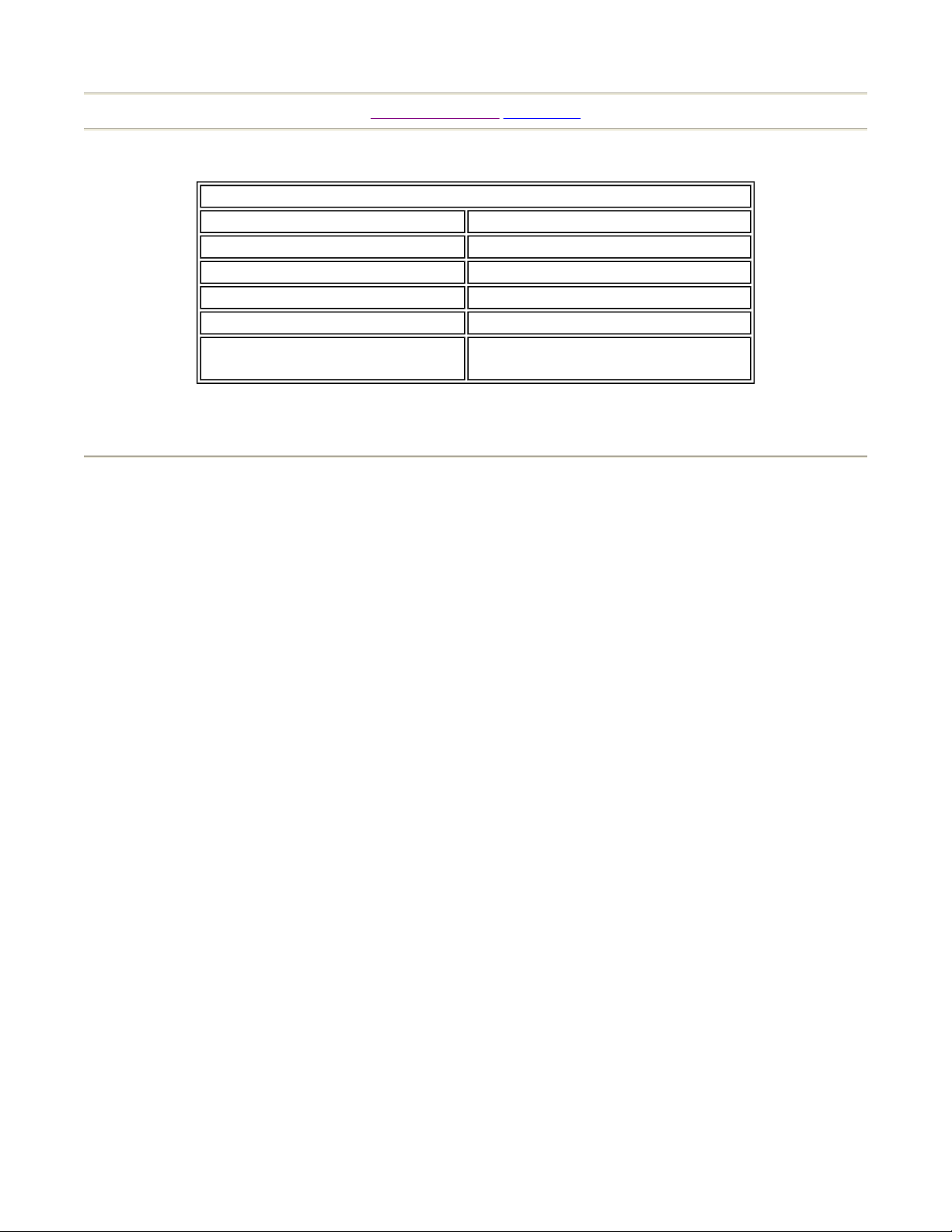
SPECIFICATIONS
WIDTH 62.5 in
DEPTH 59 in
HEIGHT 72 in
WEIGHT Approx. 475 kg. (1200 Ibs.
POWER, MAXIMUM CURRENT 900W 7.5A (AC 120V 60 Hz AREA
MONITOR
25 INCH MEDIUM RESOLUTION
COLOR MONITOR X 2
NOTE: Descriptions in this manual are subject to change without prior notice.
Page 1 of 1Introduction of the Owner's Manual
INTRODUCTION OF THE OWNER'S MANUAL
SEGA ENTERPRISES, LTD., supported by its high electronic technology of LSI's,
microprocessors, etc. and a wealth of experience, has for more than 30 years been supplying
various innovative and popular game machines to the world market. This Owner's Manual
is intended to provide detailed descriptions together with all the necessary information
covering the general operation of electronic assemblies, electromechanicals, servicing
control, spare parts, etc. as regards DAYTONA USA TWIN TYPE, a new SEGA product.
This manual is intended for those who have knowledge of electricity and technical expertise
especially in ICs, CRTs, microprocessors, etc. Carefully read this manual to acquire
sufficient knowledge before working on the machine. Should there be a malfunction, nontechnical personnel should under no circumstances touch the interior system. Should such a
case arise, contact our Main Office or the closest branch office listed as follows:
SEGA ENTERPRISES, INC. (U.S.A.) / CUSTOMER SERVICE
45133 Industrial Drive, Fremont, California 94538, U.S.A.
Phone: (650) 632-7500
Fax: (650) 632-7594
7/8/2005http://www.sauservice.com/manuals/Daytona%20Folder/DThtml/DT02.html
Page 2
N
k
y
r
)
r
r
k
g
d
Page 1 of 2Daytona USA Twin Owner's Manual
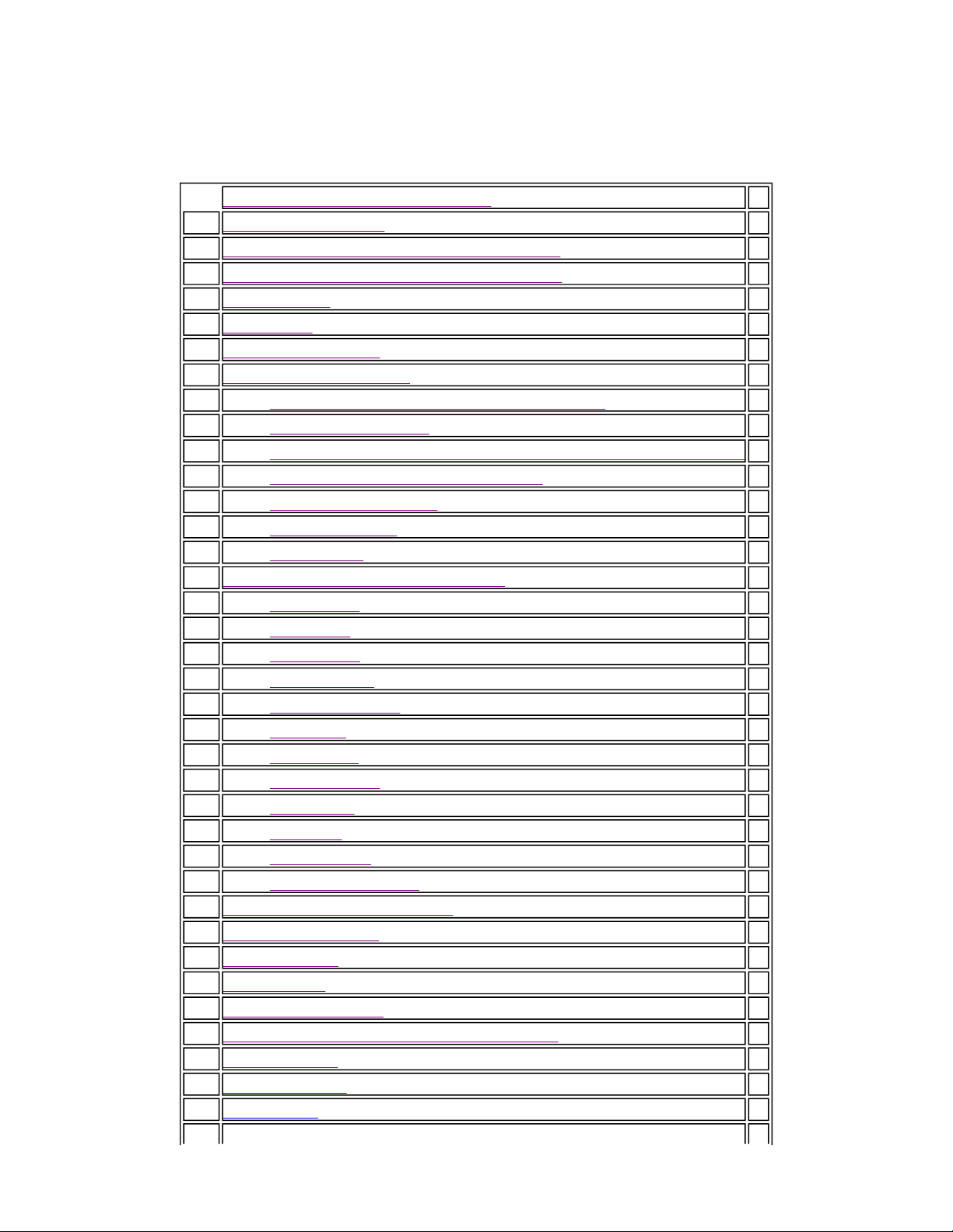
DAYTONA USA TWIN
Introduction of the Owner's Manual 2
1. Handling Precautions 3
2. Prevention of Counterfeiting and Conversion 4
3. Precautions Concerning Installation Location 5
4.
5. Accessories 7
6. Moving the Machine 8
7. Assembling the Machine 9
7-1 Assembling Your Daytona USA Twin Game 9
7-2 Billboard Installation 13
7-3 Securing to the Installation Position (Leg Adjuster Adjustment)14
7-4 Power Supply and Earth Connection 15
7-5 Turning the Power On 15
7-6 Assembly Chec
7-7 How to Play 18
8. Explanation of Test and Data Displa
8-1 Switch Unit 21
8-2 Test Mode 22
8-3 Bookeeping 23
8-4 Game System 25
8-5 Coin Assignment 26
8-6 Input Test 28
8-7 Output Test 29
8-8 Drive DB Test 30
8-9 Sound Test 32
8-10 TGP Test 33
8-11 Memory Test 33
8-12 Backup RAM Clea
9. Control Panel (Handle Mecha
10. Accelerator & Brake 37
11. 4 Speed Shifte
12. Coin Selecto
13. Monitor Adjustments 42
14. Replacing the Fluorescent Lamp, and Lamps 43
15. Periodic Chec
16. Troubleshootin
17. Game Boar
ame of Parts 6
TABLE OF CONTENTS
16
20
34
35
38
41
43
44
46
7/8/2005http://www.sauservice.com/manuals/Daytona%20Folder/DThtml/DT01.html
Page 3
y
)
)
)
R
)
)
Page 2 of 2Daytona USA Twin Owner's Manual
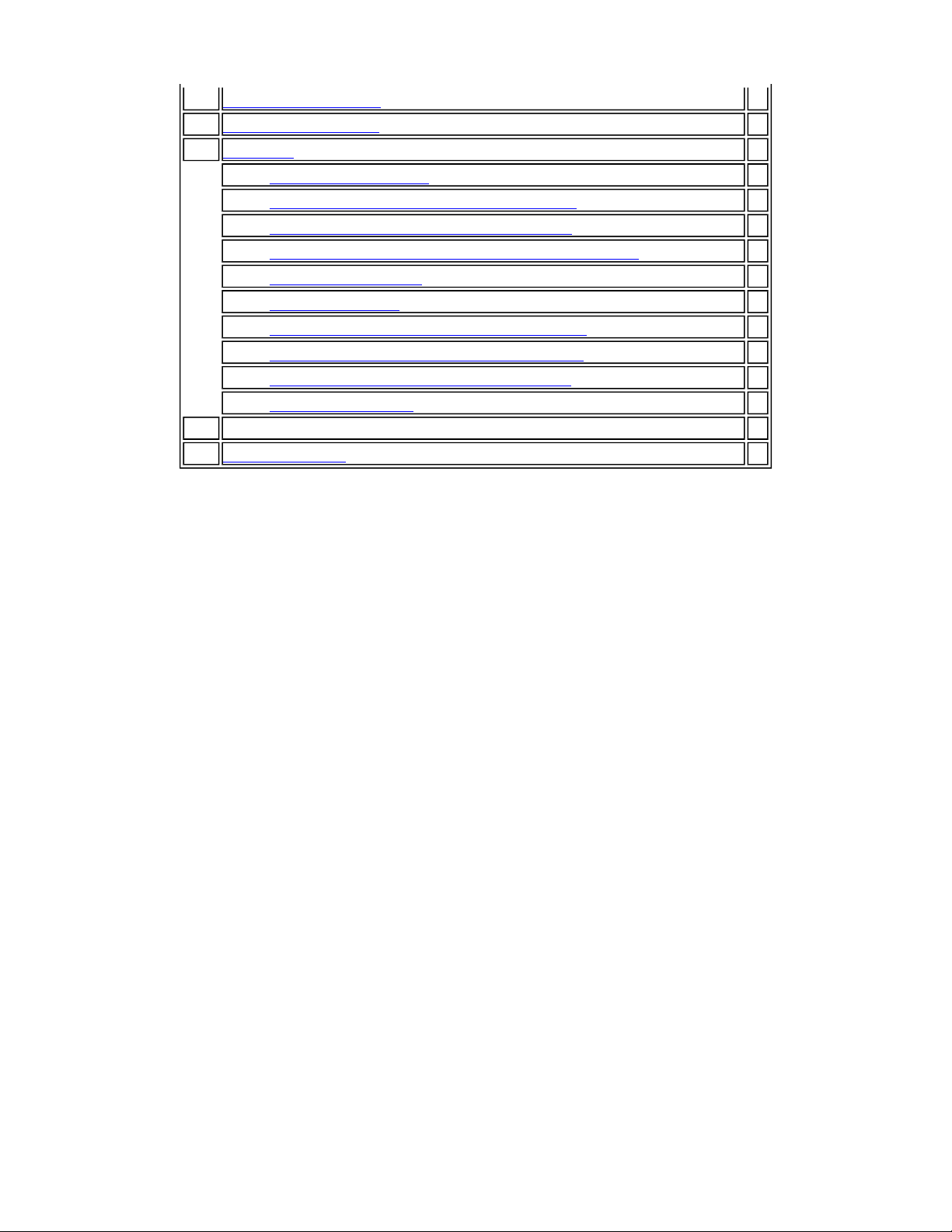
18. Communication Pla
19. Design Related Parts 52
20. Parts List 54
ASSY BILLBOARD 57
ASSY CONT PNL TWIN (DYN-12001
ASSY HANDLE MECHA (DYN-1250
ASSY VIRTUAL BUTTON TWIN (DYN-1290
ASSY SEAT TWIN 64
SEAT WOOFE
SPEAKER ASSEMBLY LEFT & RIGHT 66
ASSY 4 SPEED SHIFTER (DYN1-2150
ASSY ACCEL & BRAKE (DYN-1300
ASSY BASE BOX 71
21. Wire Color Code Table 72
22. Wiring Diagram 72
48
58
60
63
65
67
69
7/8/2005http://www.sauservice.com/manuals/Daytona%20Folder/DThtml/DT01.html
Page 4
[Table of Contents] [Previous Page] [Next Page]
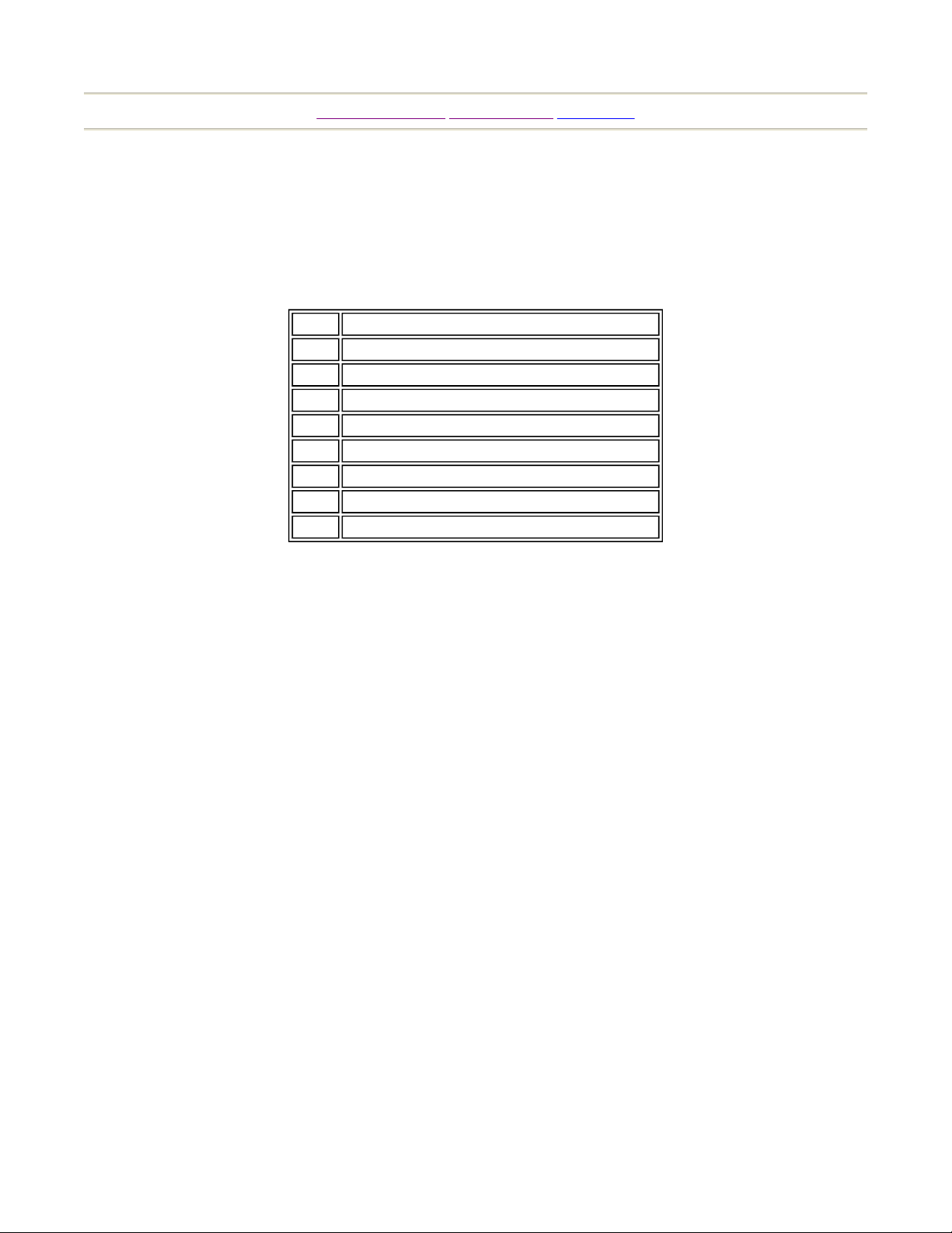
5. ACCESSORIES
When transporting the machine, make sure that the following ports are supplied.
TABLE 5 ACCESSORIES
QTY. PART NAME
2 KEY
1 OWNERS MANUAL DAYTONA TWIN
1 500 CM OPTO CABLE
1 T15 TAMPER PROOF WRENCH
1 T20 TAMPER PROOF WRENCH
1 T25 TAMPER PROOF WRENCH
1 T27 TAMPER PROOF WRENCH
1 SEAT LABELS 3-8
Page 1 of 1Accessories
7/8/2005http://www.sauservice.com/manuals/Daytona%20Folder/DThtml/DT07.html
Page 5
N
ame of Parts
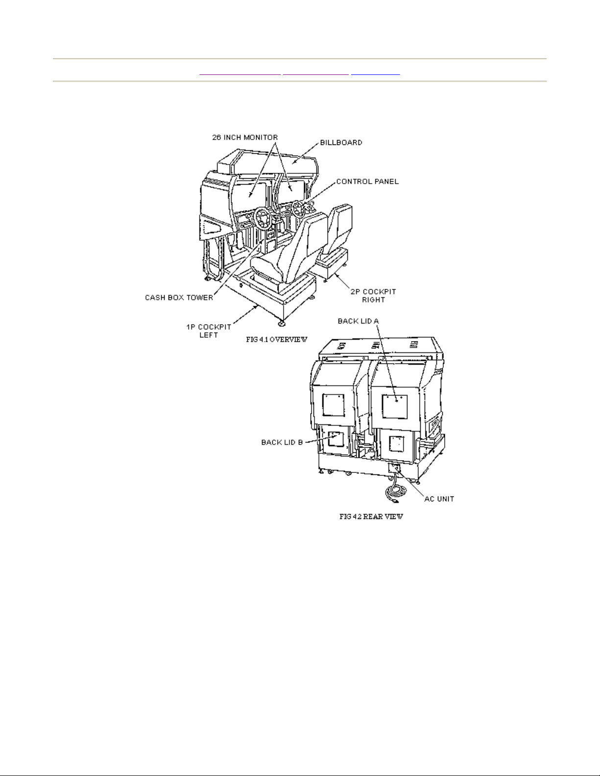
4. NAME OF PARTS
Page 1 of 1
[Table of Contents] [Previous Page] [Next Page]
7/8/2005http://www.sauservice.com/manuals/Daytona%20Folder/DThtml/DT06.html
Page 6

)
Page 1 of 1Precautions Concerning Installation Location
[Table of Contents] [Previous Page] [Next Page]
3. PRECAUTIONS CONCERNING INSTALLATION LOCATION
The DAYTONA USA TWIN TYPE is an indoor game machine. Absolutely do not install it
outside. Even indoors, avoid installing in places mentioned below so as to ensure proper
usage:
{
Places subject to rain or water leakage, or condensation due to humidity.
{
In the proximity of an indoor swimming pool and/or shower.
{
Places subject to direct sunlight.
{
Places subject to heat sources from heating units, etc., or hot air.
{
Vicinity of highly inflammable/volatile chemicals or hazardous matter.
{
Sloped surfaces.
{
Vicinity of anti-disaster facilities such as fire exits and fire extinguishers.
{
Places subject to any type of violent impact.
{
Dusty places.
INSTALLATION PRECAUTIONS
{
1) Do not insert more than one electrical plug into the power plug socket.
2) The per unit standard voltage/amperage is 100~120V/15A.
3) Use of extension cables should be avoided. If you must use, ensure the extension cables
are rated at 15A or higher for 100~120 volt areas or 10A.
4) Note that for transporting the machine into the location's building, the minimum
necessary dimensions of the opening (of doors, etc.) are 36 in (W) and 80 in (H).
5) For the operation of this machine, secure a minimum area of 80 in (W) x 70 in (D).
ELECTRIC CURRENT CONSUMPTION
MAX. 7.5 A (AC 120V 60HZ
7/8/2005http://www.sauservice.com/manuals/Daytona%20Folder/DThtml/DT05.html
Page 7

Page 1 of 1Handling Precautions
[Table of Contents] [Previous Page] [Next Page]
1. HANDLING PRECAUTIONS
When installing or inspecting the machine, be very careful of the following points and pay
attention to ensure that the player can enjoy the game safely.
{
Be sure to turn the power off before working on the machine.
{
To insert or pull out the plug quickly is dangerous.
{
It is necessary to make sure that the power cord or the grounding wire is not exposed on the
road, etc. in a manner so as to be dangerous. Make sure that grounding connections are
made safely at the position where so specified.
{
Do not use any fuse that does not meet specified rating.
{
Make complete connections for the IC board and other connectors. Insufficient insertion is
very dangerous.
{
The operating (ambient) temperature range is from 5°C to 40°C.
{
When cleaning the CRT surfaces, use a soft, dry cloth. Do not apply chemicals such as
thinner, benzene, etc.
Also, for the IC board circuit inspections, only the logic tester is allowed. The use of a tester
is not permitted, so be careful in this regard.
After confirming that there are no irregularities, turn the power ON.
7/8/2005http://www.sauservice.com/manuals/Daytona%20Folder/DThtml/DT03.html
Page 8
Page 1 of 1Prevention of Counterfeiting and Conversion
[Table of Contents] [Previous Page] [Next Page]
2. PREVENTION OF COUNTERFEITING AND CONVERSION
LABELING
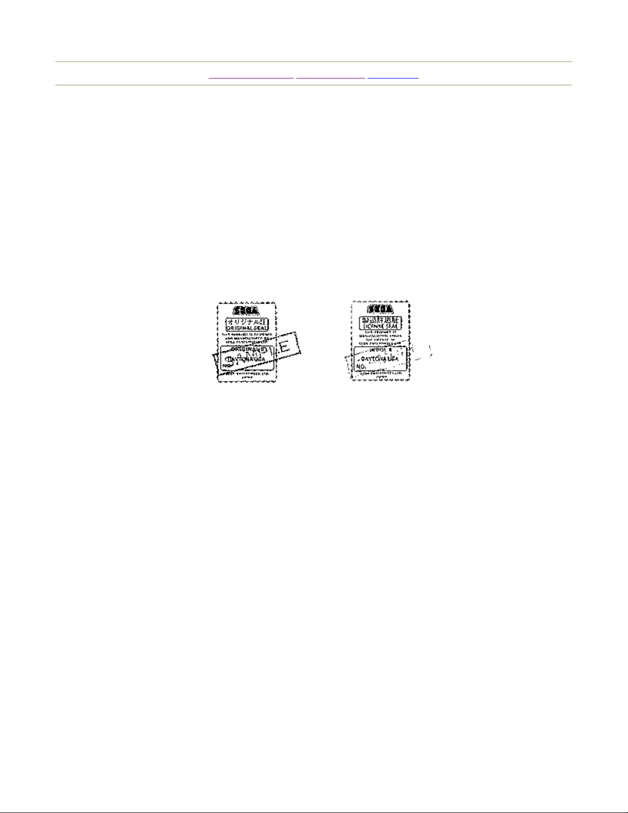
To prevent counterfeits and conversions, the following labels are put on all SEGA products.
When handling such goods, be sure to confirm the labels. They are used to prevent illegal
acts such as the unauthorized copying of the products and the printed circuit boards thereof
or carrying on business by manufacturing similar merchandise or by converting, selling or
using such products or printed circuit boards.
ORIGINAL SEAL:
LICENSE SEAL:
The left seal is put on the machines manufactured by SEGA.
The right seal is put on all SEGA kits, such as the printed circuit board.
COPYRIGHT NOTICE
This SEGA product has the copyright notice as follows:
(C) SEGA 1994
This signifies that this work was disclosed in 1994 and is the property of SEGA
ENTERPRISES, LTD.
7/8/2005http://www.sauservice.com/manuals/Daytona%20Folder/DThtml/DT04.html
Page 9

N
Page 1 of 2Moving the Machine
[Table of Contents] [Previous Page] [Next Page]
6. PRECAUTIONS TO BE HEEDED WHEN ASSEMBLING AND MOVING THE
MACHINE
WARNING:
1. Perform the assembly work by following the procedure herein stated. Failing to comply with the
instructions, for example, inserting the plug into an outlet at the stage not mentioned in this
manual might cause an electric shock accident.
2. Assembling should be performed as per this manual. Since this is a complex machine, erroneous
assembling may cause damage to the machine, or malfunctioning to occur.
3. When assembling, be sure to perform the work by plural persons.
When carrying out the assembly work, follow the procedure in the following sequence:
ASSEMBLING THE COCKPIT
INSTALLING THE BILLBOARD
SECURING IN PLACE (LEG ADJUSTER ADJUSTMENT)
INSTALLING THE AC COVERS (WIRING CONNECTION)
POWER SUPPLY, AND EARTH CONNECTION
TURNING THE POWER ON
ASSEMBLING CHECK
ote that the master key and the cashbox door key (accessories) in addition to the tools such as a plus
screwdriver, wrench for M16 hexagon bolt and socket wrench are required for the assembly work.
CAUTION:
Perform the tightening of hexagon bolts described above after adjusting the leg adjusters. Make sure that
until the leg adjuster adjustments are made, keep the hexagon bolts tightened temporarily.
7/8/2005http://www.sauservice.com/manuals/Daytona%20Folder/DThtml/DT08.html
Page 10
Page 2 of 2Moving the Machine
7/8/2005http://www.sauservice.com/manuals/Daytona%20Folder/DThtml/DT08.html
Page 11

g
Page 1 of 1Assembling Your Game
[Table of Contents] [Previous Page] [Next Page]
7. ASSEMBLING THE MACHINE
(1) ASSEMBLING YOUR DAYTONA USA TWIN GAME
To assemble your Daytona driving game locate the Left cabinet (side with on/off switch),
Cash Box Tower, and Right side cabinet.
In the parts bag located in the cash box locate the Opto cable. This will be needed later, to
connect together the opto connections on the rear of Cash Box Tower. The hardware needed
to assemble your Daytona driving game has game threaded into the proper holes. This was
done to insure the bolts thread properly into the T nuts in the cabinet.
At this time remove the rear cover of the Cash Box Tower.
Notice the wire harness taped to the sides of the cabinets and Cash Box Tower. On the wire
harness connections Black is for Left side, Yellow is for Right side viewed from front.
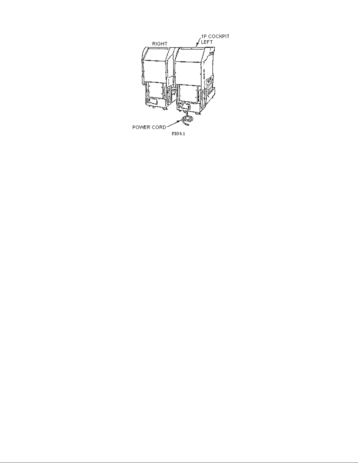
Locate Left side cabinet (on/off switch) and Cash Box Tower. (Fig 6.1A). Connect the 15,
4, and 2 position connectors together. At this time connect the Opto cable (without white
label) to the Opto connection nearest to the Left side of cabinet (viewed from front). These
Opto connections are in the rear of the Cash Box Tower.
You may elect not connect the connector at this time, but carefully push the connectors in
the hole so they are still accessible form the outside of the cabinet.
There are 4 bolts in NON SLOTTED holes, on the side of the cabinet, the 2 on top under
the ledge must be removed. The 2 on the bottom must be loosened about a 1/4 inch. Lift up
the Cash Box Tower and using the 2 lower slotted holes on the bottom of the cash box slip
them over the lower protruding bolts and slide the cash box into place. Open the coin door
and install the 2 upper bolts through the cash box into the cabinet. Tightened all 4 bolts.
The Right side cabinet gets installed the same way as left side (Fig. 6.1B).
Don't forget to connect all the connectors described above. The opto cables with the white
labels get connected together inside the rear Cash Box Tower. The 2 remaining opto cables
get connected to the 2 external opto connectors on the rear of the Cash Box Tower. This is
used for linkin
2 or more games (Fig. 6.1C). Replace the Cash Box Tower rear cover.
7/8/2005http://www.sauservice.com/manuals/Daytona%20Folder/DThtml/DT09.html
Page 12

g
Page 1 of 1Assembling Your Game
[Table of Contents] [Previous Page] [Next Page]
7. ASSEMBLING THE MACHINE
(1) ASSEMBLING YOUR DAYTONA USA TWIN GAME
To assemble your Daytona driving game locate the Left cabinet (side with on/off switch),
Cash Box Tower, and Right side cabinet.
In the parts bag located in the cash box locate the Opto cable. This will be needed later, to
connect together the opto connections on the rear of Cash Box Tower. The hardware needed
to assemble your Daytona driving game has game threaded into the proper holes. This was
done to insure the bolts thread properly into the T nuts in the cabinet.
At this time remove the rear cover of the Cash Box Tower.
Notice the wire harness taped to the sides of the cabinets and Cash Box Tower. On the wire
harness connections Black is for Left side, Yellow is for Right side viewed from front.
Locate Left side cabinet (on/off switch) and Cash Box Tower. (Fig 6.1A). Connect the 15,
4, and 2 position connectors together. At this time connect the Opto cable (without white
label) to the Opto connection nearest to the Left side of cabinet (viewed from front). These
Opto connections are in the rear of the Cash Box Tower.
You may elect not connect the connector at this time, but carefully push the connectors in
the hole so they are still accessible form the outside of the cabinet.
There are 4 bolts in NON SLOTTED holes, on the side of the cabinet, the 2 on top under
the ledge must be removed. The 2 on the bottom must be loosened about a 1/4 inch. Lift up
the Cash Box Tower and using the 2 lower slotted holes on the bottom of the cash box slip
them over the lower protruding bolts and slide the cash box into place. Open the coin door
and install the 2 upper bolts through the cash box into the cabinet. Tightened all 4 bolts.
The Right side cabinet gets installed the same way as left side (Fig. 6.1B).
Don't forget to connect all the connectors described above. The opto cables with the white
labels get connected together inside the rear Cash Box Tower. The 2 remaining opto cables
get connected to the 2 external opto connectors on the rear of the Cash Box Tower. This is
used for linkin
2 or more games (Fig. 6.1C). Replace the Cash Box Tower rear cover.
7/8/2005http://www.sauservice.com/manuals/Daytona%20Folder/DThtml/DT09.html
Page 13

p
Page 1 of 2Billboard Installation
[Table of Contents] [Previous Page] [Next Page]
BILLBOARD INSTALLATION
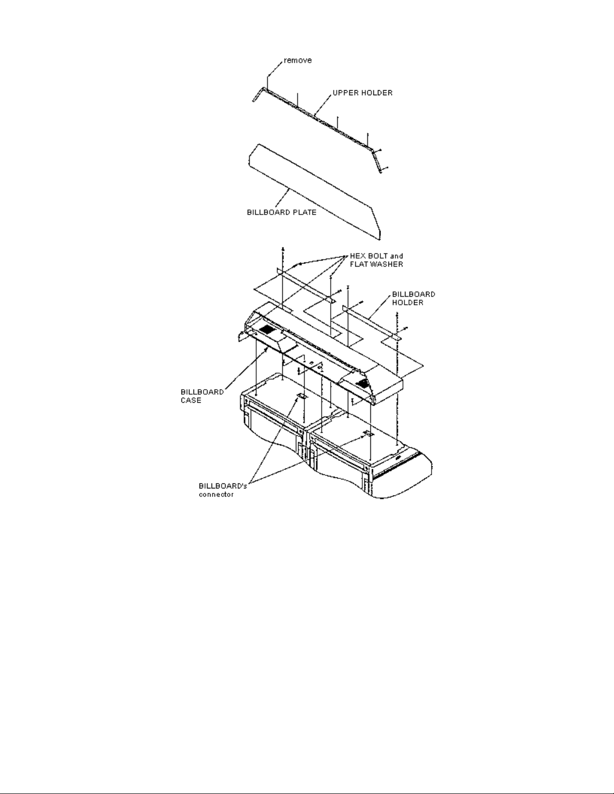
1. Remove billboard form carton and remove upper holder and billboard plate. Remove billboard
holders and hardware package from inside billboard case.
Remove (8) 5/16 in hex bolts from top of cabinet.
2. Attach billboard holders to rear of billboard case thru vertical slots with (4) 5/16 - 18 x 1" lg hex
bolts and flat washers, lightly tighten.
3. Mount billboard case across top of both cabinets and attach with (4) 5/16 - 18 x 1" lg hex bolts
and flat washers thru mtg. holes. Do not tighten.
4. Loosen billboard holders on rear of case and align over mtg. holes. Secure with (4) 5/16 -18 x 1"
lg hex bolts and flat washers.
5. Align billboard case and tighten all mtg. bolts.
6. Connect the (3) billboard connectors. Two (blue & white) connectors on left side, 9 (blue) on right
side. There is a extra white connector on Right side that is not used.
7. Re
lace billboard plate and upper holder.
7/8/2005http://www.sauservice.com/manuals/Daytona%20Folder/DThtml/DT13.html
Page 14
Page 2 of 2Billboard Installation
7/8/2005http://www.sauservice.com/manuals/Daytona%20Folder/DThtml/DT13.html
Page 15

b
Page 1 of 2Leg Adjuster Adjustment
[Table of Contents] [Previous Page] [Next Page]
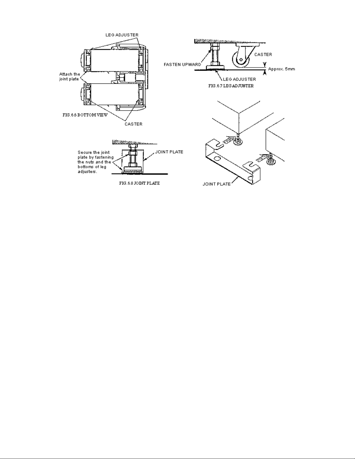
(3) SECURING TO THE INSTALLATION POSITION (LEG ADJUSTER ADJUSTMENT)
WARNING!
Make sure that all of the leg adjusters are in contact with the floor. If they are not, the cabinet may move
and cause an accident to occur.
This machine has eight casters and eight leg adjusters (Fig 6.6). When the installation position is
determined, cause the leg adjusters to come into contact with the floor directly, make adjustments in a
manner so that the casters will be raised approximately 5 mm. from the floor and make sure that the
machine position is level.
1. Move the machine to the installation position. When installing the machine against or close to a
wall, be sure to secure a passage space to enable the player to take a ride in the machine.
2. Attach the joint plate for the 2 internal leg adjusters shown. First, cause the other 6 leg adjusters to
come into contact with the floor. Make leg adjuster adjustments with a wrench in a manner to
ensure the machine's position is level (Fig. 6.6).
3. After making adjustments, fasten the leg adjuster nut upward and secure the height of the leg
adjuster (Fig. 6.7).
4. Insert the notch portions of the joint plate to the 2 leg adjusters.
5. Lower the leg adjuster and fasten the nut upward. Secure the joint plate with the nuts and the
ottoms of the leg adjuster (Fig. 6.8).
7/8/2005http://www.sauservice.com/manuals/Daytona%20Folder/DThtml/DT14.html
Page 16
Page 2 of 2Leg Adjuster Adjustment
7/8/2005http://www.sauservice.com/manuals/Daytona%20Folder/DThtml/DT14.html
Page 17
[Table of Contents] [Previous Page] [Next Page]
N
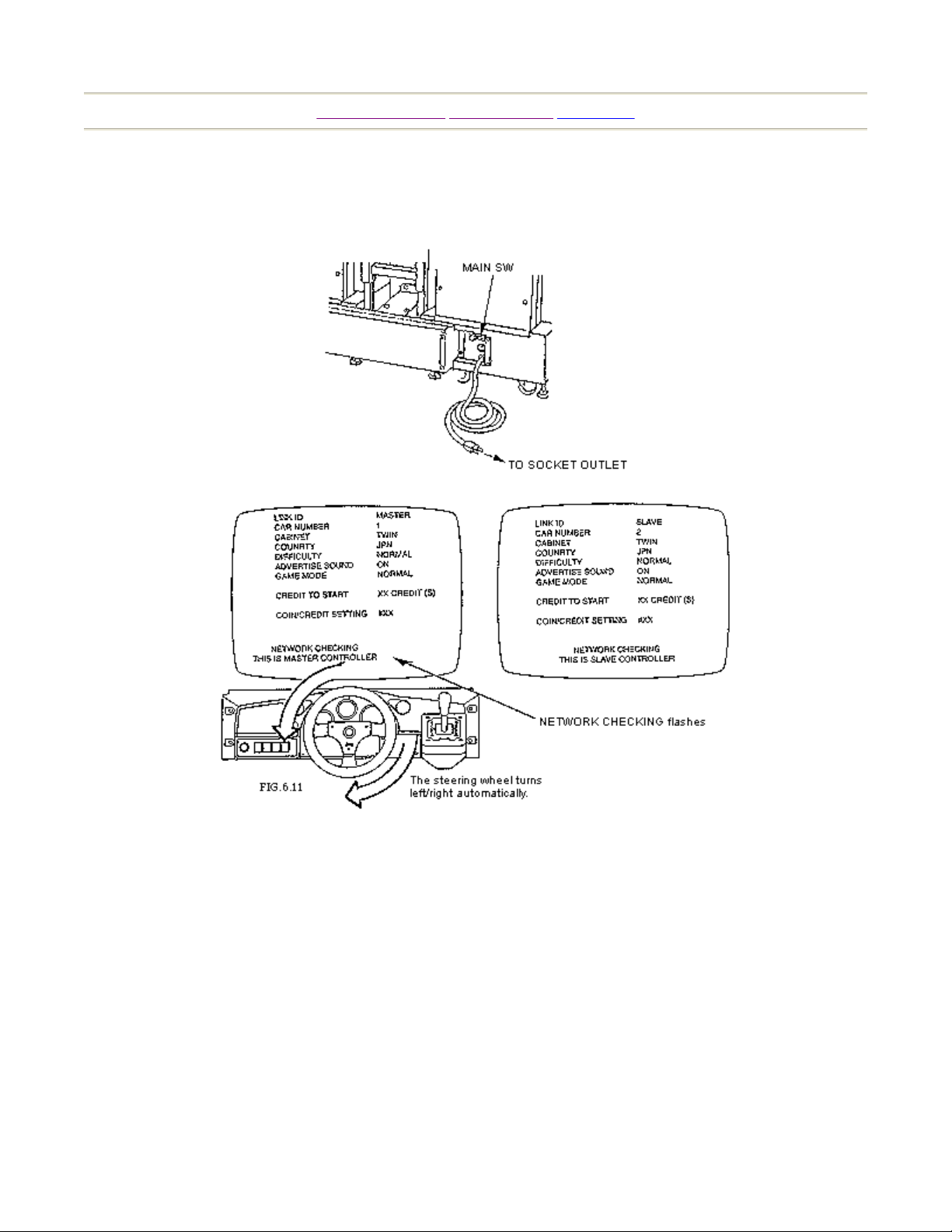
(4) POWER SUPPLY AND EARTH CONNECTION
The AC UNIT is located on the back of the 1P cockpit (cabinet).
Page 1 of 2Power, Earth & Power On
(5) TURNING THE POWER ON
Turning the AC UNIT's MAIN SW on will cause the machine to start the POWER ON check and
ETWORK check automatically.
In the POWER ON check, the steering wheel turns left and right, then returns to the centering position
and stops. In this check, the values of V.R. inside the control panel are corrected. Until the check is
finished (the steering wheel stops automatically), do not touch the steering wheel or play the game.
If you do, the steering wheel reaction during the game (reaction at the time of a course-out or crashing)
can not be obtained correctly.
In a case of a strange reaction during the game, turn the power on again from the beginning and
complete the power-on check.
7/8/2005http://www.sauservice.com/manuals/Daytona%20Folder/DThtml/DT15.html
Page 18

Page 2 of 2Power, Earth & Power On
During network checking, "NETWORK CHECKING" flashes on the screen. At this time, current
settings are displayed on the screen. When NETWORK CHECKING is finished, the DEMO mode will
appear on the monitor screen.
7/8/2005http://www.sauservice.com/manuals/Daytona%20Folder/DThtml/DT15.html
Page 19
Page 1 of 1Assembly Chec
k
[Table of Contents] [Previous Page] [Next Page]
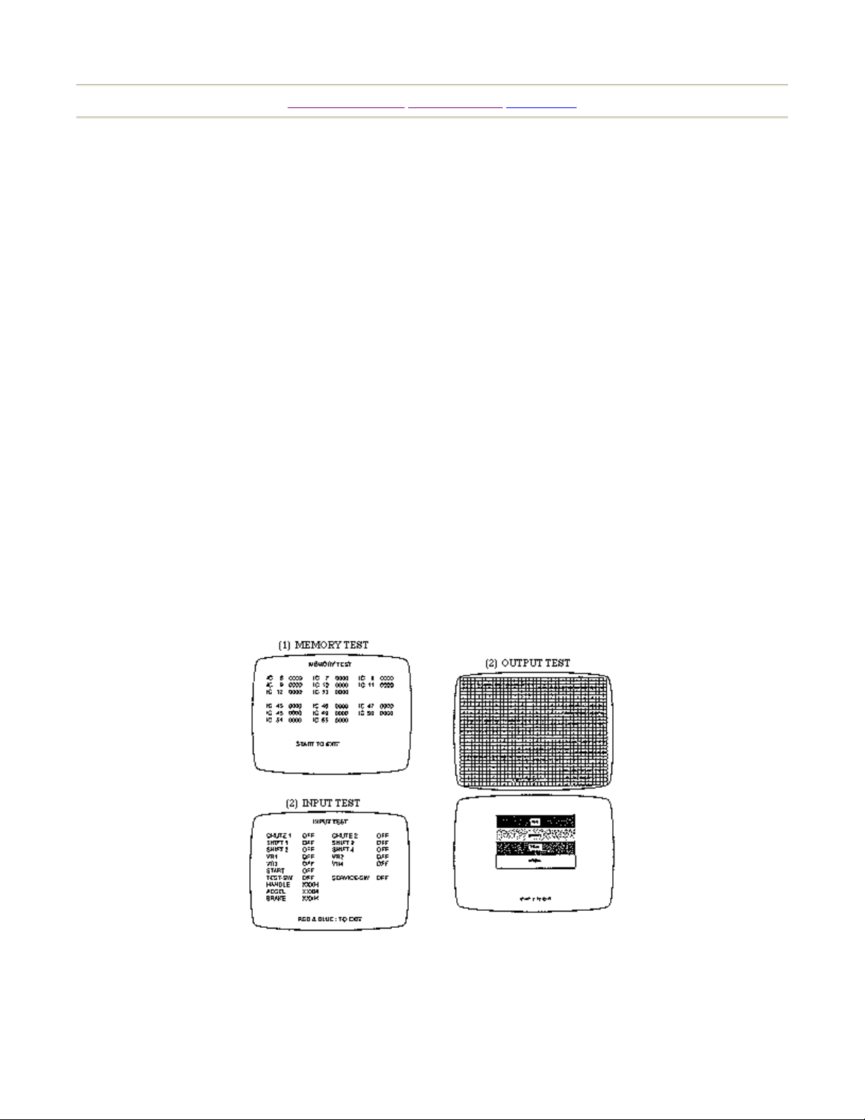
(6) ASSEMBLY CHECK
In the TEST MODE, ascertain that the assembly has been made correctly and IC BD., is satisfactory
(refer to Section 8).
In the test mode, perform the following test:
Selecting the MEMORY TEST on the test mode menu screen causes the on-board memory to be tested
automatically. The game board is satisfactory if the display beside each IC No. shows GOOD.
Selecting the INPUT TEST on the test mode menu screen causes the screen (on which each switch and
V.R. are tested) to be displayed. Press each switch. For the coin switch test, insert a coin from the coin
inlet with the coin chute door being open. If the display beside each switch indicates "ON", the switch
and wiring connections are satisfactory.
Ascertain the display of V.R. value for the steering wheel and accelerator & brake. If the V.R. values are
not satisfactory, refer to Sections 9 & 10.
In the TEST mode menu, selecting OUTPUT TEST allows the screen (on which the monitor is tested) to
be displayed. Although the monitor adjustments have been made at the time of shipment from the
factory, make judgment (by watching the test mode screen) as to whether an adjustment is needed. If it
is necessary, adjust the monitor by referring to Section 13.
7/8/2005http://www.sauservice.com/manuals/Daytona%20Folder/DThtml/DT16.html
Page 20

p
Page 1 of 2How to Pla
y
[Table of Contents] [Previous Page] [Next Page]
7-1 HOW TO PLAY
The following explanations apply to the case that each seat has an independent coin entry. In the case
where a coin entry is used in common by 2 seats, the starting procedure is different.
1. Take a ride in the machine. The seat position can be adjusted forward and backward. For
adjustments, pull the lever which is positioned on the lower left-hand side (facing the monitor
screen) of the seat.
2. The coin chute door is located at the center in the front of the cabinet. Insert a coin into the
corresponding coin entry and press the start button.
3 courses appear on the screen in the sequence of Beginner, Advanced and Expert starting form
the left.
3. At this time, "WAITING FOR YOUR ENTRY" is displayed on the other players' monitors and a
countdown of 14 seconds to start will begin. The person who desires to compete with the first
player is to insert a coin into the coin entry for his seat within the 14 seconds.
4. By turning the steering wheel, chose a course and make the selection effective by stepping on the
Accelerator. The course selection is determined by the majority of the players participating in the
"vs." competition race and not by the person who inserted a coin first.
5. SHIFT CHANGE SELECTION screen appears. Choose AUTO or MANUAL by turning the
steering wheel and effectuate the selection by stepping on the Accelerator. This selection is made
by each seat independently. While pressing the start button, if you step on the Accelerator, only
the "vs." competitor's car appears and other competitor cars will not appear. This is also
determined by the majority of the players participating in the "vs." competition.
6. When AUTO or MANUAL is determined, the game starts. Choosing the Beginner course results
in a rolling start, the same as in the Daytona race. When the Advanced or Expert course is chosen,
be sure to step on the Accelerator to start the machine.
7. The on-screen upper right-hand side, below the upper right, the upper middle, below the upper
middle, the upper left- hand side and the lower right respectively indicates the player's present
osition, where other cars are, time limit, speed & tachometer, lap time and course map.
7/8/2005http://www.sauservice.com/manuals/Daytona%20Folder/DThtml/DT18.html
Page 21

Page 2 of 2How to Pla
y
7/8/2005http://www.sauservice.com/manuals/Daytona%20Folder/DThtml/DT18.html
Page 22

Page 1 of 2Explanation of Test and Data Displa
y
[Table of Contents] [Previous Page] [Next Page]
8. EXPLANATION OF TEST AND DATA DISPLAY
By operating the switch unit, periodically perform the tests and data check. When installing the machine
initially or collecting cash, or when the machine does not function correctly, perform checking in
accordance with tile explanations given in this section. The following shows tests and modes that should
be utilized as applicable.
CAUTIONS TO BE HEEDED WHEN USING THE TEST MODE
Exiting from the test mode causes the unit to perform the network check automatically. During this time,
all of the linked units will not allow the game to be played in normal status. Therefore, be sure not to
enter the test mode if any one of the units is in play. On the other hand, if even one unit is in the mode,
make sure that other machines are not in play.
TABLE 8.1 EXPLANATION OF TEST MODE
ITEMS DESCRIPTION
INSTALLATION OF
MACHINE
When the machine is installed, perform the following:
1. Check to see that each setting is as per standard setting
made at the time of shipment.
2. In the INPUT TEST mode, check each SW and VR. 8 - 6, 8 - 8
3. in the OUTPUT TEST mode, check each of lamps. 8 - 7
4. In the SELF-TEST mode, check ICs on the IC Board. 8 -10, 8-11
MEMORY Choose MEMORY TEST in the MENU mode to allow the
memory test to be performed. In this test, PROGRAM
RAMs, ROMs, and ICs on the IC Board are checked.
PERIODIC
SERVICING
Periodically perform the following:
1. MEMORY TEST 8 - 10, 8 - 11
2. Ascertain each setting. 8 - 4, 8 - 5
3. In the INPUT TEST mode, test the CONTROL device. 8 - 6, 8 - 8
4. In the OUTPUT TEST mode, check each of lamps. 8 - 7
CONTROL SYSTEM 1. In the INPUT TEST mode, check each SW and VR. 8 - 6, 8 - 8
2. Adjust or replace each SW and VR. 9, 10, 11
3. If the problem can not be solved yet, check the
CONTROL's moves.
MONITOR In the MONITOR ADJUSTMENT mode, check to see if
the MONITOR adjustment is appropriately made.
IC BOARD 1. MEMORY TEST 8 - 10, 8 - 11
2. In the SOUND TEST mode, check the sound related
ROMs.
REFERENCE
SECTIONS
8 - 4, 8 - 5
8 - 10, 8 - 11
8 - 7, 13
8 - 9
7/8/2005http://www.sauservice.com/manuals/Daytona%20Folder/DThtml/DT20.html
Page 23

Page 2 of 2Explanation of Test and Data Displa
y
DATA CHECK Check such data as game play time and histogram to adjust
the difficulty level, etc.
8 - 3
7/8/2005http://www.sauservice.com/manuals/Daytona%20Folder/DThtml/DT20.html
Page 24

pag
Page 1 of 1Switch Unit
[Table of Contents] [Previous Page] [Next Page]
8-1 SWITCH UNIT
FIG. 8.1 SWITCH UNIT
Open the coin chute door, and the switch unit shown will appear. The functioning of each SW is as
follows:
TEST SWITCH: For the handling of the test button, refer to the following pages.
SERVICE SWITCH: Gives credits without registering on the coin meter.
SOUND VOLUME: Adjusts the volume of the monitor's right-hand side and left-hand side
speakers, the control panel's right/left tweeters and the superwoofer under the
seat.
DEMAGNETIZER
SWITCH:
Eliminates color unevenness from the screen.
The control panel switches are also used in the test mode. For each functioning, refer to the following
e and onward.
7/8/2005http://www.sauservice.com/manuals/Daytona%20Folder/DThtml/DT21.html
Page 25
8-2 TEST MODE
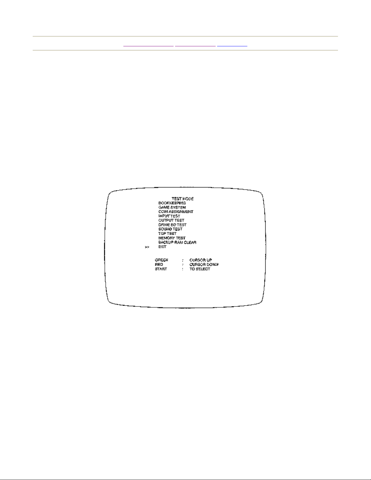
z
The Test Menu allows the functioning of each part of the Cabinet to be checked, the MONITOR
to be adjusted, and the coins and game related various settings to be performed.
z
Press the TEST SWITCH to cause the following Test Menu to be displayed on the monitor. (FIG.
8.2)
z
Press the SERVICE SWITCH until the pointer ">>" is moved to the desired item Also, note that
pressing VR1 (red) causes the arrow to move downward and pressing VR4 (green) causes the
arrow to move upward.
z
Bring the pointer ">>" to the desired test item and press either the TEST SWITCH or START
BUTTON to cause the selected item's test to start.
Page 1 of 1Test Mode
[Table of Contents] [Previous Page] [Next Page]
FIG. 8.2 TEST MENU
After the test is complete, move ">>" to "EXIT" and press the TEST SWITCH or START BUTTON to
return to the Game Mode.
7/8/2005http://www.sauservice.com/manuals/Daytona%20Folder/DThtml/DT22.html
Page 26

Page 1 of 1Bookkeepin
g
[Table of Contents] [Previous Page] [Next Page]
8-3 BOOKKEEPING
Selecting the BOOKKEEPING in the menu mode causes the bookkeeping data up to the present to be
displayed on 2 pages.
z
Press the TEST SW or START BUTTON to return to the MENU mode screen.
z
Press VR1 (red) to proceed to the other page.
FIG. 8.3a BOOKKEEPING
z
COIN CHUTE #*: Number of coins put in. As seen from the front of the cabinet, the right-hand
side is #1 and the left-hand side is #2.
z
TOTAL COINS: Total number of activations of coin chutes.
z
COIN CREDITS: Number of credits registered by inserting coins.
z
SERVICE CREDITS: Credits registered by the SERVICE switch.
z
TOTAL CREDITS: Total number of credits (COIN CREDITS + SERVICE CREDITS)
z
TOTAL TIME: The total energized time.
7/8/2005http://www.sauservice.com/manuals/Daytona%20Folder/DThtml/DT23.html
Page 27

N
y
N
Page 1 of 2Game System
[Table of Contents] [Previous Page] [Next Page]
8-4 GAME SYSTEM
Selecting the GAME SYSTEM in the menu mode causes the present game setting to be displayed and
also the game setting changes can be made. Each item displays the following content.
FIG. 8.4 GAME SYSTEM
LINK ID: For communication (interactive) play, set one seat to "MASTER" and the rest of the
seats to "SLAVE". The game setting and coin setting, etc. of the MASTER seat apply
to the slave seats also. Note that setting changes made by the SLAVE seats are not
effective for the game.
CAR
UMBER:
For interactive play between 2 or more machines (cabinets), the cabinets (starting from
the left, facing the monitor screen) are numbered in the sequential order of No. 1, No.
2, No. 3, No. 4, .... If the same number is used for 2 or more cabinets or cabinets are
numbered in an incorrect sequence, on-screen display may be confused.
CABINET: Setting of cabinet. Set to "TWIN" for this machine.
COUNTRY: Message language (select USA for the U.S.A., and EXPORT for other countries).
DIFFICULTY: The game difficulty is classified into 4 different categories from EASY to HARDEST.
Standard setting is "NORMAL". ADVERTISE SOUND: Advertisement sound during
. No sound is produced with "OFF". Standard setting is "OFF".
ORMAL (8,4 and 2 laps respectively for Beginner, Advanced and Expert.) GRAND
GAME
MODE:
standb
Selection of laps. Allows laps to be changed for specific attraction event purposes.
PRIX (20,10 and 5 laps respectively for Beginner, Advanced and Expert).
ENDURANCE (80, 40 and 20 laps respectively for Beginner, Advanced and Expert).
RIVAL
ARROW:
Selection of ARROW(s) indicating rival car(s). ON to display. OFF not to display.
SETTING CHANGE PROCEDURE
1. Press the SERVICE SW or VR1 (red), or VR 4 (green) to move the arrow (>>) to the desired
item.
2. Choose the desired setting change item by using any one of VR2 (blue), VR3 (yellow), TEST SW
and START BUTTON.
7/8/2005http://www.sauservice.com/manuals/Daytona%20Folder/DThtml/DT25.html
Page 28

Page 2 of 2Game System
3. To return back to the MENU mode, move the arrow to EXIT and press the TEST SW or START
BUTTON.
7/8/2005http://www.sauservice.com/manuals/Daytona%20Folder/DThtml/DT25.html
Page 29
Page 1 of 1Coin Assignment
[Table of Contents] [Previous Page] [Next Page]
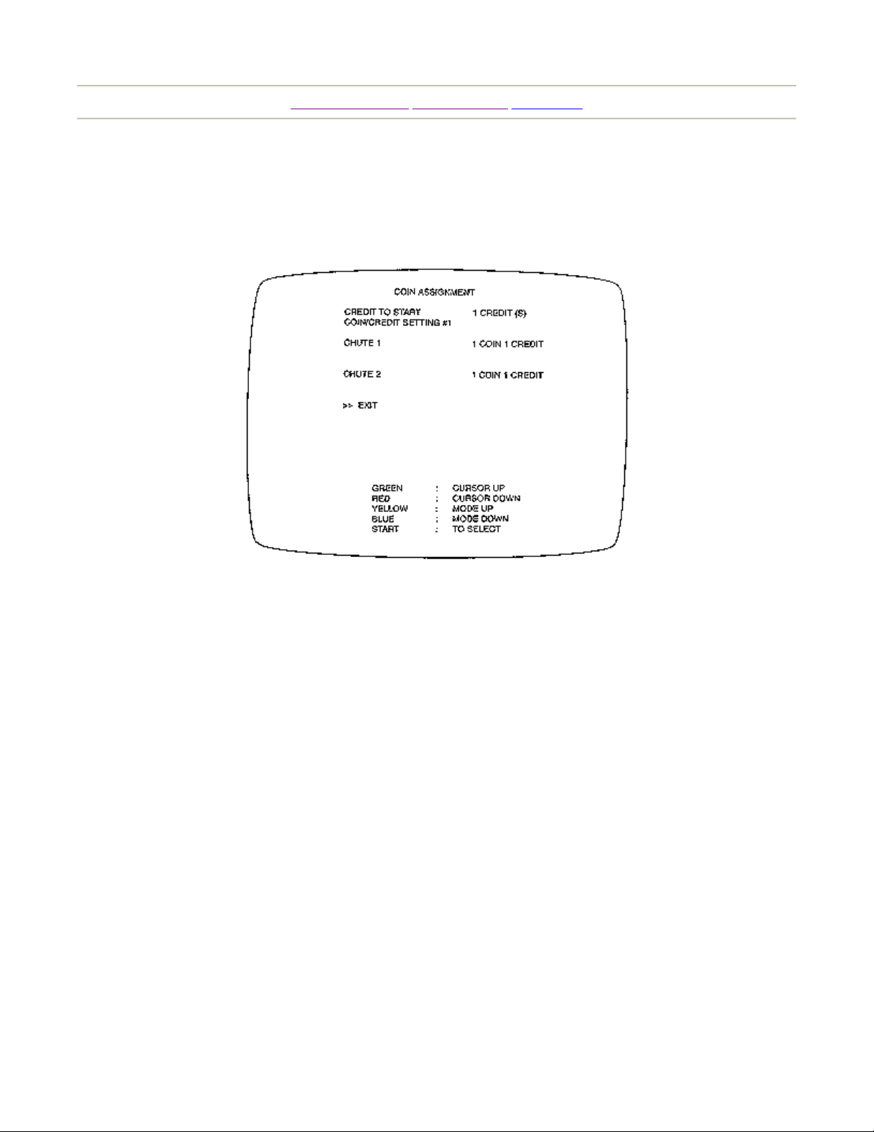
8-5 COIN ASSIGNMENT
The "COIN ASSIGNMENTS" mode permits you to set the start number of credits, as well as the basic
numbers of coins and credits. This mode expresses "how many coins correspond to how many credits".
FIG. 8.5 COIN ASSIGNMENTS
z
CREDIT TO START: Number of credits required for starting game (1-5 credits are selected.)
z
COIN/CREDIT SETTING: "How many coins correspond to how many credits." In this machine,
selection as per Table 8.2 is possible.
SETTING CHANGE PROCEDURE
1. Press the SERVICE SW or VR1 (red), or VR4 (green) to move the arrow (>>) to the desired item.
2. Choose the desired setting change item by using any one of VR2 (blue), VR3 (yellow), TEST SW
and START BUTTON.
3. To return back to the MENU mode, move the arrow to EXIT and press the TEST SW or START
BUTTON.
7/8/2005http://www.sauservice.com/manuals/Daytona%20Folder/DThtml/DT26.html
Page 30

(
)
(
)
(
)
Page 1 of 1Input Test
[Table of Contents] [Previous Page] [Next Page]
8-6 INPUT TEST
When INPUT TEST is selected, the monitor will show the following, allowing you to watch the status
of each switch and the value of each V.R. of the CONTROL PANEL.
On this screen, periodically check the status of each switch & V.R.
z
By pressing each switch, if the display on the right-hand side of the name of each switch changes
to ON from OFF, the SW and the wiring connections are satisfactory.
z
To check CHUTE 1 & CHUTE 2 coin switches, open the COIN CHUTE DOOR and insert a coin
(s) from the coin entry.
z
To return back to the MENU mode, simultaneously press VR1 & VR2, or press the TEST SW.
FIG. 8.6 INPUT TEST
HANDLE: Under 2DH <-- 7D~83H --> Over D3H
ACCEL: Under 30H --> Over COH
BRAKE: Under 30H --> Over D2H
An appropriate value of each V.R. is as follows:
left
the pedal released
Centering position
the pedal stepped
right
7/8/2005http://www.sauservice.com/manuals/Daytona%20Folder/DThtml/DT28.html
Page 31

8-7 OUTPUT TEST
Choose OUTPUT TEST to cause the following topmost screen to appear. In this test,
periodically adjust the monitor and check the status of each lamp.
The first FIG. below shows the menu mode of OUTPUT TEST. Press the SERVICE SW or
VR4 (green) / VR1 (red) and bring the arrow (>>) to the desired test item.
Press the TEST SW or START BUTTON to cause the test mode screen below to appear. To
return back to the menu mode, bring the arrow to EXIT and press the TEST SW or START
BUTTON (FIG. 8.2)
Choose CRT SIZE to cause the crosshatch screen to appear.
Adjust the monitor to make sure that the crosshatch lines do not go beyond the screen size
and crosshatch distortion does not occur. Press the START BUTTON to return to the above
OUTPUT TEST menu screen.
Choose CRT COLOR to cause the colored-bar screen shown below to appear. This test
allows the on-screen color adjustment to be performed. The color of a color bar (for each of
the 4 colors, i.e., red, green, blue, and white) is darkest at the left most end and brightest at
the rightmost end. Press the START BUTTON to return to the above OUTPUT TEST menu
screen.
Choose LAMP to cause the last screen shown below to appear. This enables the status of
each lamp to be checked. Causes the START button lamp, the lamp of each V.R. switch,
and LEADER lamp to light up in a sequential order. Press the START button to return to
the above OUTPUT TEST menu screen.
Page 1 of 2Output Test
[Table of Contents] [Previous Page] [Next Page]
7/8/2005http://www.sauservice.com/manuals/Daytona%20Folder/DThtml/DT29.html
Page 32

Page 2 of 2Output Test
FIG. 8.7 OUTPUT TEST
7/8/2005http://www.sauservice.com/manuals/Daytona%20Folder/DThtml/DT29.html
Page 33

y
(
g
Page 1 of 1Drive BD Test
[Table of Contents] [Previous Page] [Next Page]
8-8 DRIVE BD TEST
Choosing DRIVE BD TEST allows the reaction mechanism of the steering wheel to be checked. Also,
this enables the V.R. value for the steering wheel's DRIVE BD and the setting status of the DIP SWes
on the Drive BD to be checked.
FIG. 8.8 DRIVE BD
Bring the arrow (>>) to the desired item by using the SERVICE SW or VR1 (red) or VR4 (green). The
steering wheel functions to the setting selected by the arrow. Pressing VR2 (blue) or VR3 (yellow)
allows the force transmitted to the steering wheel to increase or decrease.
SPRING:
Status in which the motor and clutch are not activated. Centering of the handle is
caused b
only the spring inside the handle mechanism.
CLUTCH: Status in which the clutch is activated. The handle is fixed.
CENTERING: Status in which the handle
of itself) returns to the center position.
UNCENTERING:Status in which the handle is caused not to be in the center.
ROLL LEFT: Status in which the handle is rotated in the left-hand side direction
ROLL RIGHT: Status in which the handle is rotated in the ri
ht-hand side direction.
EXIT: Causes the menu mode to return on to the screen.
7/8/2005http://www.sauservice.com/manuals/Daytona%20Folder/DThtml/DT30.html
Page 34

p
Page 1 of 2Sound Test
[Table of Contents] [Previous Page] [Next Page]
8-9 SOUND TEST
Choosing SOUND TEST causes the following mode to appear on the screen. This allows the desired
sound (BGM, announcement and sound effects) to be chosen and heard. Enables the SOUND BD, AMP
BD and each speaker to be checked.
Press the SERVICE SW or VR1 (red) or VR4 (green) and bring the arrow (>>) to the desired sound item
to be tested. Pressing the TEST SW or START BUTTON allows the selected sound test to be
erformed.
FIG. 8.9 SOUND TEST
z
AUTO: Auto play covering from BGM to RESULT.
Bring the arrow to this item and press TEST SW or START BUTTON to cause SOUND TEST
covering from BGM to RESULT will be automatically and repeatedly be performed.
z
BGM: Background music during game.
z
SE: Sound effects during game.
z
VOICE: Announcement and comment during game.
z
NAME: Announcement and comment during name entry.
z
RESULT: Announcement during the display of the results.
z
ENGINE: Engine/Slip/Brake sounds can be emitted by using the ACCEL. pedal, HANDLE pedal
and BRAKE pedal respectively.
7/8/2005http://www.sauservice.com/manuals/Daytona%20Folder/DThtml/DT32.html
Page 35

z
EXIT: Causes the menu mode to return on to the screen.
Page 2 of 2Sound Test
7/8/2005http://www.sauservice.com/manuals/Daytona%20Folder/DThtml/DT32.html
Page 36

Page 1 of 2TGP & Memory Tests
[Table of Contents] [Previous Page] [Next Page]
8-10 TGP TEST
In this test, TGP (on-screen display related IC) is checked. As shown below, if "GOOD" is displayed for
all, it is satisfactory. Press TEST SW or START BUTTON to return to the menu screen.
FIG. 8.10 TGP TEST
FIG. 8.11 MEMORY TEST
8-11 MEMORY TEST
The MEMORY TEST mode is for checking the on-BD memory IC functioning. "GOOD" is displayed
for normal ICs and "BAD" is displayed for abnormal ICs.
z
When the test is completed, if the results are shown as above, it is satisfactory.
z
It takes approximately thirty seconds to complete the test. If the period exceeds thirty seconds, this
may have been caused by board malfunctioning.
7/8/2005http://www.sauservice.com/manuals/Daytona%20Folder/DThtml/DT33.html
Page 37

Page 2 of 2TGP & Memory Tests
z
After finishing the test, pressing the TEST SW or START BUTTON allows the MENU mode to
return on to the screen.
7/8/2005http://www.sauservice.com/manuals/Daytona%20Folder/DThtml/DT33.html
Page 38

Page 1 of 1Backup RAM Clea
r
[Table of Contents] [Previous Page] [Next Page]
8-12 BACKUP RAM CLEAR
Clears the contents of BOOKKEEPING.
When clearing, bring ">>" to "YES" and when not clearing, to "NO", by using the SERVICE SW or
VR1 (red)/VR4 (green), and then push the TEST SW or START BUTTON.
When the data has been cleared, "COMPLETED" will be displayed. Bring ">>" to "NO" and press the
TEST SW to cause the Menu mode to return on to the screen.
Also, note that the game setting contents are not affected by BACKUP RAM CLEAR operation.
FIG. 8.12 BACKUP RAM
7/8/2005http://www.sauservice.com/manuals/Daytona%20Folder/DThtml/DT34.html
Page 39

p
Page 1 of 2Control Panel (Handle Mecha
)
[Table of Contents] [Previous Page] [Next Page]
9. CONTROL PANEL (HANDLE MECHA)
In the TEST mode, if the steering wheel V.R. value variations are not within the allowable range, an
adjustment of the V.R. installation position or replacement of the V.R. are needed. Also, apply grease to
the steering wheel mechanism's shaft and sliding portions once every 3 months.
To perform the above work, take off the 2 screws and remove BACK LID A from the back of the
cockpit.
CAUTION!
Removing BACK LID A causes the monitor's high tension portion to be exposed. When
erforming the following work. Be very careful in this regard.
9-1 REPLACING AND ADJUSTING THE HANDLE's (STEERING WHEEL's) V.R.
The upper side V.R. of the HANDLE MECHA is for the GAME BD., and the lower side one, for the
DRIVE BD.
Check the value of the V.R. for the DRIVE BD. The appropriate value of each V.R. is as follows:
V.R. for the GAME BD.: Under 2 DH <-- 7DH~33H --> Over D3H
V.R. for the DRIVE BD.: Under 2 DH <-- 7DH~83H --> Over D3H
METHOD OF V.R. REPLACEMENT
To replace the V.R., after taking off the connector form the V.R. to be replaced, take out the 2 screws
7/8/2005http://www.sauservice.com/manuals/Daytona%20Folder/DThtml/DT35.html
Page 40

Page 2 of 2Control Panel (Handle Mecha
)
which secure the VR BRACKET, and remove the V.R. together with the bracket and gear. After the
replacement, check the V.R. value variations in the test mode.
FIG. 9.2
7/8/2005http://www.sauservice.com/manuals/Daytona%20Folder/DThtml/DT35.html
Page 41

Page 1 of 2Accelerator & Brake
[Table of Contents] [Previous Page] [Next Page]
10. ACCELERATOR & BRAKE
In the test mode, if the ACCEL. & BRAKE V.R. value is not within the allowable range, an adjustment
of V.R. installation position, or a replacement of V.R. is needed. Also, grease the MECHA's shafts and
sliding portions once every 3 months.
To perform the above work, take off the 2 screws and remove BACK LID B from the back of the
cockpit.
10-1 ADJUSTMENT AND REPLACEMENT OF VOLUME
The ACCEL. & BRAKE MECHA can be seen by removing the front lid. The ACCEL. V.R. is on the
left- hand side and the BRAKE F.R. is on the right-hand side of the MECHA. Check the V.R. value in
the test mode. The appropriate value of each V.R. is as follows:
When released: When stepped on:
ACCEL.: Under 2 DH <---> Over D3H
BRAKE: Under 2 DH <---> Over D3H
METHOD OF V.R. REPLACEMENT
To replace the V.R., after taking off the connector from the V.R. to be replaced, take out the 2 screws
which secure the VR BRACKET, and remove the V.R. together with the bracket and gear. After the
replacement, check the V.R. value variations in the test mode.
7/8/2005http://www.sauservice.com/manuals/Daytona%20Folder/DThtml/DT37.html
Page 42

Page 2 of 2Accelerator & Brake
7/8/2005http://www.sauservice.com/manuals/Daytona%20Folder/DThtml/DT37.html
Page 43

Page 1 of 24 Speed Shifte
r
[Table of Contents] [Previous Page] [Next Page]
METHOD OF V.R. ADJUSTMENT
1. Loosen the 2 screws which secure the V.R. BRACKET, move the V.R. BRACKETS and
disengage the gears.
2. Cause the V.R. value to match with the value obtained when the pedal is released.
3. Cause the gears to be engaged and secure the V.R. BRACKET. At this time, be sure to obtain an
appropriate backlash.
4. Step on the pedal and check the V.R. value variation.
10-2 GREASING
Grease the gears and bearings once every 3 months as a standard.
11. 4 SPEED SHIFTER
In the test mode, if the shift lever input is found to be irregular, replace the switch or adjust the switch
installation position. Also, grease the MECHA's shafts or sliding portions once every 3 months as a
standard.
When performing the above work, remove the shift lever unit.
11-1 REMOVING THE SHIFTER
1. Take off the 4 screws and remove SHIFT COVER A.
2. Take out the 4 SPECIAL BOLTs and pull out the SHIFT LEVER UNIT upward by paying careful
attention so as not to cause damage to the wiring.
3. Disconnect CONNECTOR 6P and remove the shift lever unit.
7/8/2005http://www.sauservice.com/manuals/Daytona%20Folder/DThtml/DT38.html
Page 44

Page 2 of 24 Speed Shifte
r
7/8/2005http://www.sauservice.com/manuals/Daytona%20Folder/DThtml/DT38.html
Page 45

p
Page 1 of 2Coin Selecto
r
[Table of Contents] [Previous Page] [Next Page]
12. COIN SELECTOR
HANDLING THE COIN JAM
Even when the REJECT button is pressed, if the coin is not rejected, open the coin chute door and open
the selector gate. After removing the jammed coin, put a normal coin in and check to see that the
selector correctly functions.
CLEANING THE COIN SELECTOR
1. Turn the power for the machine OFF. Open the coin chute door.
2. Open the gate and dust off by using a soft brush (made of wool, etc.).
3. Remove stain by wiping with a soft cloth which contains water or chemicals detergent.
4. Remove the CRADLE. When removing the retaining ring (E ring), b very careful so as not to
bend the shaft.
5. Remove stain from the shaft and pillow portions by wiping off with a soft cloth, etc.
6. After wiping off a per 5 above, further apply a dry cloth, etc. to cause the coin selector to dry
com
letely.
7/8/2005http://www.sauservice.com/manuals/Daytona%20Folder/DThtml/DT41.html
Page 46

N
Page 2 of 2Coin Selecto
r
OTE:
Absolutely do not apply machine oil, etc. to the coin selector.
After cleaning the coin selector, insert a regular coin in the normal working status and ascertain that the
selector correctly functions.
7/8/2005http://www.sauservice.com/manuals/Daytona%20Folder/DThtml/DT41.html
Page 47

[Table of Contents] [Previous Page] [Next Page]
(1) R
(2)
(3)
(4)
(5)
(6)
(7)
(8)
(9)
(10)
13. MONITOR ADJUSTMENTS
CAUTION!
z
z
z
Remove LID A on rear of cabinet to make the monitor adjustments (refer to 9.3).
Do not operate the ADJUSTMENT knobs without good reason.
A certain portion of the monitor is subject to a high voltage and therefore be very careful of this
point.
When making adjustment, utilize a resinous Alignment Screwdriver.
Page 1 of 1Monitor Adjustments
NANAO monitor: 24K mode
Model: MS 8-2654
2001-5187-15
-GAIN
G-GAIN Controls colors.
B-GAIN
BRIGHT Controls horizontal brightness.
H. SIZE Controls horizontal screen size.
H. HOLDProvides horizontal synchronization, i.e., controls right/left blurring of image.
H. POSI Controls horizontal display position on screen.
V. SIZE Controls vertical screen size.
V. HOLDProvides vertical synchronization, i.e., controls up-down scrolling of image.
V. POSI Controls vertical display position on screen.
[11] H. POSI Controls the visual quality. (Only applies to Nanao.)
A: Ordinary, B: Super-sharpness
7/8/2005http://www.sauservice.com/manuals/Daytona%20Folder/DThtml/DT42.html
Page 48

[Table of Contents] [Previous Page] [Next Page]
y
y
y
y
y
R
y
y
y
y
14. REPLACING THE FLUORESCENT LAMP, AND LAMPS
In a manner as shown below, remove the parts and replace the fluorescent lamp.
Page 1 of 1Lamps
FIG. 14
15. PERIODIC CHECK
The items listed below require periodic check and maintenance to retain the performance of this
machine and to ensure safe business operation.
ITEM INTERVAL REFERENCE
CONTROL Check lamp. Monthl
Check VOLUME VALUE. Monthl
Check ADJUST GEAR engagement. Trimonthly9 -1
Greasing of GEAR and bearing. Trimonthly9 - 2
ACCEL. & BRAKE Check VOLUME VALUE. Monthl
Check ADJUST GEAR engagement. Trimonthly10 - 1
Greasing of GEAR and bearing. Trimonthly10 - 2
4 SPEED SHIFTER Check SW. Monthl
Greasing of bearing. Trimonthly11 - 3
Check RUBBER STOPPERs. Semi-yearly11 - 4
COIN CHUTE TOWERCheck COIN SW. Monthl
Cleaning of COIN SELECTOR. Trimonthly12
MONITO
SEAT Antistatic measures. Bimonthl
GAME BD MEMORY TEST. Monthl
Check adjustments. Monthl
Check settings. Monthl
8
6, 8
6, 8
6, 8
8
6, 8, 13
5
8
8
7/8/2005http://www.sauservice.com/manuals/Daytona%20Folder/DThtml/DT43.html
Page 49

[Table of Contents] [Previous Page] [Next Page]
b
b
b
gag
(
p
g
g
)
g
16. TROUBLESHOOTING
In case a problem occurs, first check wiring connector connections.
PROBLEMS CAUSES COUNTERMEASURES
When the main SW is
turned ON, the machine is
not activated.
MONITOR screen is
blackened and the
fluorescent lamp does not
light up.
MONITOR screen is all
lue.
The color of image on
MONITOR screen is
incorrect.
The on-screen image of the
monitor sways and/or
shrinks.
Control panel and pedal
are not satisfactorily
operable.
SHIFT LEVER doesn't
operate satisfactorily.
Steering Wheel reaction
strength is insufficient.
The power is not ON. Firmly insert the plug into the outlet.
Incorrect power
source/voltage.
AC UNIT CIRCUIT
PROTECTOR functioned due
to instantaneous overcurrent.
Power supply unit fuse blown
off due to instantaneous
overcurrent.
Defective connections in
etween each board.
Make sure that the power supply/voltage are
correct.
First, remove the cause of overcurrent and
reinstate the circuit protector to it's original
status (refer to Sec. 6).
First remove the cause of overcurrent, then
replace the fuse (refer to Sec. 17).
FUSE 10A 250V
Make sure of correct connections in
etween each board.
Incorrect monitor adjustment. Make appropriate adjustments (see Sec. 13).
The power source and voltage
are not correct.
V.R. position deviated, or
V.R. malfunctioning.
ADJUST GEAR's
ement is not correct.
en
Switch position deviated, or
switch malfunctioning.
POWER ON CHECK not
erformed correctly.
V.R. position deviated, or
V.R. malfunctionin
.
Reaction mecha's secular
e.
chan
Make sure that the power supply and
voltage are correct.
Adjust or replace the V.R. (see Sec. 9 &
10).
Adjust the engagement of ADJUST GEAR
see Sec. 9 & 10).
Adjust or replace the Switch (see Sec. 11).
SW MICRO TYPE
First turn the power off and then turn it back
on again. Complete the POWER ON
CHECK.
Adjust or replace the V.R. (see Sec. 9).
Change DRIVE BD DIP SW setting (see
Sec. 8 & 17
.
Page 1 of 1Troubleshootin
7/8/2005http://www.sauservice.com/manuals/Daytona%20Folder/DThtml/DT44.html
Page 50

Page 1 of 2Game Boar
d
[Table of Contents] [Previous Page] [Next Page]
17. GAME BOARD
17-1 REMOVING THE BOARD
To replace the IC BD (such as Game BD, Drive BD, etc.), or to change DIP SW settings, take out the IC
BD by using the following procedure:
1. Turn the MAIN SW off.
2. Unlock and take off the 2 truss screws from the side of the base as shown.
3. Turn the knob to unlock. The seat can be inclined in the direction shown. When inclining the seat,
be careful so as not to damage the seat parts. Carefully cause the backrest portion of the seat to
come into contact with the floor.
If the floor has hard surfaces, protect the seat form damage by using a cloth, etc. on the floor
surfaces.
4. Take off the 3 screws to remove the case lid. The GAME BD and I/O BD are incorporated in the
shield case.
5. Take off a total of 4 screws from both sides with the seat being in an inclined state and remove
BASE UD F. Removing BASE LIS F allows the power supply unit, drive BD and sound BD to be
checked.
Fuses are placed in the power supply.
7/8/2005http://www.sauservice.com/manuals/Daytona%20Folder/DThtml/DT46.html
Page 51

Page 2 of 2Game Boar
d
7/8/2005http://www.sauservice.com/manuals/Daytona%20Folder/DThtml/DT46.html
Page 52

Page 1 of 1Communication Pla
y
[Table of Contents] [Previous Page] [Next Page]
18. COMMUNICATION PLAY
This machine allows up to 8 persons to play simultaneously by linking plural units.
18-1 INSTALLATION PRECAUTIONS
1. When linking a number of machines, be sure to supply sufficient power for the corresponding
number of machines. The pre unit standard voltage/amperage is 100~120V/15A.
2. Due to the length of the communications cable, the distance in between the machines will be
approximately 8 in. or less.
7/8/2005http://www.sauservice.com/manuals/Daytona%20Folder/DThtml/DT48.html
Page 53
[Table of Contents] [Previous Page] [Next Page]
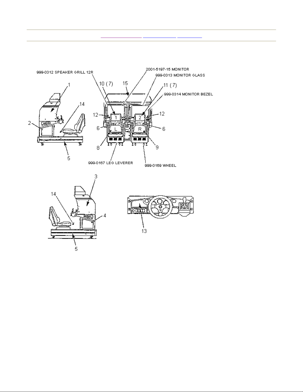
19. DESIGN RELATED PARTS
Page 1 of 1Parts List
FIG. 19
7/8/2005http://www.sauservice.com/manuals/Daytona%20Folder/DThtml/DT52.html
Page 54

[Table of Contents] [Previous Page] [Next Page]
p
R
r
y
y
r
p
Page 1 of 1Parts List
ITEM PART NUMBE
DESCRIPTION
1 Fuse 10A* 5A s/o, 6A
2 999-0307 Power Transforme
3 999-0102 150W Power Suppl
4 838-10646 Motor Driver BD
5 950-0045 or 450-5054 Solid State Rel
6 838-10141-03 Mixer Seq. Amp for S. Woofe
7 601-6227-01 Power Am
* Note 10A fuse not used on right side. Always replace fuse with same type and rating for continued
rotection against risk of fire.
7/8/2005http://www.sauservice.com/manuals/Daytona%20Folder/DThtml/DT54.html
Page 55

(2) ASSY BILLBOARD
R
R
ITEM PART NUMBERDESCRIPTION
1 DYN1-0201 BILLBOARD CASE
2 DYNO-0202 BILLBOARD PLATE
3 LAMP UNIT
4 FL UNIT 30W
5 DYN1-0203 UPPER HOLDE
6 DYN1-0204 SIDE HOLDE
Page 1 of 1Parts List
[Table of Contents] [Previous Page] [Next Page]
INCANDESCENT BULB 25W 120V
7/8/2005http://www.sauservice.com/manuals/Daytona%20Folder/DThtml/DT57.html
Page 56

[Table of Contents] [Previous Page] [Next Page]
(10) ASSY CONT PNL TWIN (DYN-12001)
Page 1 of 1Parts List
7/8/2005http://www.sauservice.com/manuals/Daytona%20Folder/DThtml/DT58.html
Page 57

[Table of Contents] [Previous Page] [Next Page]
R
R
R
ASSY VIRTUAL BUTTON TWIN (DYN-1290)
Page 1 of 1Parts List
ITEM PART NUMBE
DESCRIPTION NOTE
1 DYN-1291 VR BUTTON BRKT
2 171-6478B
PC BD LIGHTNING
SWX5
101 212-5205-12 CONN JST M 12P RTS
102 509-5560-12 PB SW W/L 6V 1L 7 YELLOW
103 509-5561-
PB SW W/L 6V 5L
RED
104 509-5561-S PB SW W/L 6V 5L S BLUE
105 509-5561-Y PB SW W/L 6V 5L Y YELLOW
106 509-5561-G PB SW W/L 6V 5L G GREEN
7/8/2005http://www.sauservice.com/manuals/Daytona%20Folder/DThtml/DT63.html
Page 58

ASSY SEAT TWIN
R
R
R
Page 1 of 1Parts List
[Table of Contents] [Previous Page] [Next Page]
ITEM PART NUMBE
DESCRIPTION NOTE
1 DYNO-2131 UPPER SEAT
2 DYNO-2132 LOWER SEAT
3 DYN1-2081 SEAT FRAME TWIN
4 DYN1-2082 SEAT BASE
5 DYN1-2084 SEAT BACK COVE
101 6011-7493 SEAT RAIL L
102 6011-7494
SEAT RAIL R W
ADJUSTE
7/8/2005http://www.sauservice.com/manuals/Daytona%20Folder/DThtml/DT64.html
Page 59

SEAT WOOFER
R
Page 1 of 1Parts List
[Table of Contents] [Previous Page] [Next Page]
ITEM PART NUMBERDESCRIPTION NOTE
101 130-5114 SPEAKER BOX SUB WOOFE
7/8/2005http://www.sauservice.com/manuals/Daytona%20Folder/DThtml/DT65.html
Page 60

[Table of Contents] [Previous Page] [Next Page]
SPEAKER ASSEMBLY LEFT & RIGHT
Page 1 of 1Parts List
ITEM PART NUMBERDESCRIPTION NOTE
101 130-5113 SPEAKER BOX DOME
7/8/2005http://www.sauservice.com/manuals/Daytona%20Folder/DThtml/DT66.html
Page 61
[Table of Contents] [Previous Page] [Next Page]
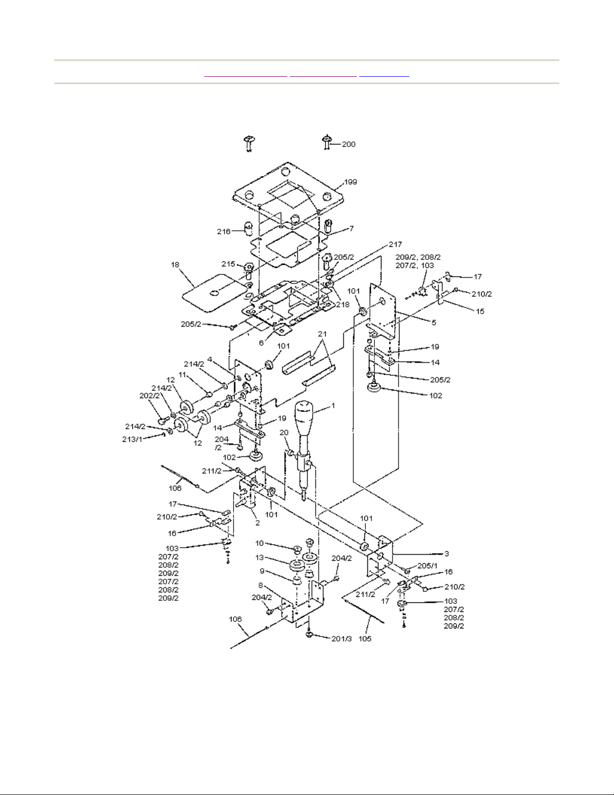
ASSY 4 SPEED SHIFTER (DYN1-2150)
Page 1 of 1Parts List
7/8/2005http://www.sauservice.com/manuals/Daytona%20Folder/DThtml/DT67.html
Page 62

[Table of Contents] [Previous Page] [Next Page]
ASSY ACCEL & BRAKE (DYN-1300)
Page 1 of 1Parts List
7/8/2005http://www.sauservice.com/manuals/Daytona%20Folder/DThtml/DT69.html
Page 63

ASSY BASE BOX
R
R
R
N
Page 1 of 1Parts List
[Table of Contents] [Previous Page] [Next Page]
ITEM PART NUMBE
DESCRIPTION NOTE
1 DYN1-2002 MAIN BASE
2 DYN1-2003 BASE LID F
3 DYN1-2004 LOCK TNG
4 DYN1-2005 FLOOR MAT
5 DYN1-2006 HINGE 480
6 DYN1-2010 ASSY BASE LID
7 DYN1-2007 LID EDGE L
8 DYN1-2009 LID EDGE
202 999-0168 LOCK & KEY #399
204 031-000514-OB
206 050-F00500
BOLT CB S NP 01032X20 SQ
UT LOCK ZN 010-24
ELHSS
WASHER FL ZN 1/2
O.D.
999-0309 LOCK CAM RIGHT
999-0310 LOCK CAM LEFT
SCREW MS 5 ST 08
32X12 56 8T TP
7/8/2005http://www.sauservice.com/manuals/Daytona%20Folder/DThtml/DT71.html
 Loading...