

Page 1
1ST PRINTING Jan ‘03
www.seuservice.com
A Redemption Game
Owner’s Manual
SEGA AMUSEMENTS USA, INC.
MANUAL NO. 999-1618
Page 2

VISIT OUR WEBSITE!
Page 3
BEFORE USING THE PRODUCT, BE SURE TO READ THE FOLLOWING:
To maintain the safety:
To ensure the safe usage of the product, be sure to read the following before using the product. The
following instructions are intended for the users, operators and the personnel in charge of the operation of the product. After carefully reading and sufciently understanding the warning displays and
cautions, handle the product appropriately. Be sure to keep this manual nearby the product or elsewhere convenient for referring to it when necessary.
Herein, explanations which require special attention are enclosed with dual lines. Depending on the
potentially hazardous degrees, the terms of WARNING, CAUTION, etc. are used. Be sure to understand the contents of the displays before reading the text.
Indicates that mishandling the product by disregarding this warning
will cause a potentially hazardous
WARNING!
situation which can result in death
or serious injury.
CAUTION!
Indicates that mishandling the product
by disregarding this caution will cause
a slight hazardous situation which can
result in personal injury and or material
damage.
For the safe usage of the product, the following pictographs are used:
Indicates “HANDLE WITH CARE.” In order to protect the human body an equipment,
this display is attached to places where the Owner’s Manual and or Service Manual should
be referred to.
Perform work in accordance with the instructions herein stated.
Instructions for work are explained by paying attention to the aspect of accident prevention. Failing to
perform work as per the instructions can cause accidents. In the case where only those who have technical expertise should perform the work to avoid hazardous situation, the instructions herein state that the
serviceman should perform such work.
Be sure to turn off power before working on the machine.
To prevent electric shock, be sure to turn off power before starting the work in which the worker touches
the interior of the product. If the work is to be performed in the power-on status, the Instruction Manual
herein always states to that effect.
Be sure to ground the Earth Terminal (this, however, is not required in the case where a power cord
with earth is used).
This product is equipped with the Earth Terminal. When installing the product, Connect the Earth Terminal to the “accurately grounded indoor earth terminal” by using an earth wire. Unless the product is
grounded appropriately, the user can be subject to electric shock. After performing repair, etc. for the
Control equipment, ensure that the Earth Wire is rmly connected to the Control equipment.
Ensure that the Power Supply used is equipped with an Earth Leakage Breaker.
This product does not incorporate the Earth Leakage Breaker. Using a power supply which is not
equipped with the Earth Leakage Breaker can cause a re when earth leakage occurs.
Be sure to use fuses which meet the specied rating. (only for the machines which use fuses).
Using fuses exceeding the specied rating can cause a re and electric shock.
Page 4

Specication changes (removal of equipment, conversion and addition) not designated by SEGA
are not allowed.
The parts of the product include warning labels for safety, covers for personal protection, etc. It is
very hazardous to operate the product by removing parts and or modifying the circuits. Should doors,
lids and protective parts be damaged or lost, refrain from operating the product, and contact where the
product was purchased from or the ofce herein stated. SEGA shall not be held responsible for any
accidents, compensation for damage to a third party, resulting from the specications not designated by
SEGA.
Ensure that the product meets the requirements of appropriate Electrical Specications.
Before installing the product, check for Electrical Specications. SEGA products have a nameplate
on which Electrical Specications are described. Ensure that the product is compatible with the power
supply voltage and frequency requirements of the location. Using any Electrical Specications different
from the designated Specications can cause a re and electric shock.
Install and operate the product in places where appropriate lighting is available, allowing warning
labels to be clearly read.
To ensure safety for the customers, labels and printed instructions describing potentially hazardous situation are applied to places where accidents can be caused. Ensure that where the product is operated
has sufcient lighting allowing the warnings to be read. If any label is peeled off, apply it again immediately. Please place an order with where the product was purchased from or the ofce herein stated.
When handling the Monitor, be very careful. (Applies only to the product w/monitor.)
Some of the monitor (TV) parts are subject to high tension voltage. Even after running off power, some
portions are still subject to high tension voltage sometimes. Monitor repair and replacement should be
performed only be those technical personnel who have knowledge of electricity and technical expertise.
Be sure to adjust the monitor (projector) properly. (Applies only to the product w/monitor.)
Do not operate the product leaving on-screen ickering or blurring as it is. Using the product with the
monitor not properly adjusted may cause dizziness or a headache to an operator, a player, or the customers.
When transporting or reselling this product, be sure to attach this manual to the product.
In the case where commercially available monitors and printers are used in this product, only the contents relating to this product are explained herein. Some commercially available equipment has functions and reactions not stated in this manual. Read this manual together with the specic Instruction
Manual of such equipment.
•
Descriptions herein contained may be subject to improvement changes without notice.
•
The contents described herein are fully prepared with due care. However, should any question arise or
errors be found, please contact SEGA.
INSPECTIONS IMMEDIATELY AFTER TRANSPORTING THE PRODUCT TO THE LOCATION.
Normally, at the time of shipment, SEGA products are in a status allowing for usage immediately after
transporting to the location. Nevertheless, an irregular situation may occur during transportation. Before
turning on power, check the following points to ensure that the product has been transported in a satisfactory status.
Are there any dented portions or defects (cuts, etc.) on the external surfaces of the cabinet?
Are Casters and Adjusters, damaged?
Do the power supply voltage and frequency requirements meet with those of the location?
Are all wiring connectors correctly and securely connected? Unless connected in the correct direction,
connector connections can not be made accurately. Do not insert connectors forcibly.
Do power cords have cuts and dents?
Do the fuses used meet specied rating? Is the Circuit Protector in an energized status?
Are all accessories available?
Can all Doors and Lids be opened with the Accessory keys? Can Doors and Lids be rmly closed?
Page 5

TABLE OF CONTENTS
BEFORE USING THE PRODUCT, BE SURE TO READ THE FOLLOWING:
TABLE OF CONTENTS
INTRODUCTION OF THE OWNER’S MANUAL
1. HANDLING PRECAUTIONS ..........................................................................................
2. PRECAUTIONS CONCERNING INSTALLATION LOCATION ...................................
3. OPERATION .....................................................................................................................
4. ASSEMBLING AND INSTALLATION ............................................................................
5. PRECAUTIONS TO BE HEEDED WHEN MOVING THE MACHINE ........................
6. NAME OF PARTS.............................................................................................................
7. GAME DESCRIPTION......................................................................................................
8. HOW TO PLAY...................................................................................................................
9. GAME SETTINGS .............................................................................................................
10. GAMEBOARD CONFIG SETTINGS.............................................................................
11. GAME ERROR CODES....................................................................................................
12. TICKET DOOR.................................................................................................................
TICKET DISPENSOR...............................................................................................
14. DESIGN RELATED PARTS.............................................................................................
15. PARTS................................................................................................................................
16. WIRING DIAGRAMS ......................................................................................................
1 - 2
3 - 4
5 - 6
7 - 9
10
11
12
13
14 - 15
16
17
18
19 - 22
23
24 - 36
XXX
Page 6
SPECIFICATIONS
Installation Space : 36 inches width X 68 inches length
Height : 67 inches
Width : 36 inches
Length : 48 inches
Weight : 392 lbs
Power, maximum current : 240W 2A (AC 120V 60 Hz AREA)
MONITOR : NO MONITOR USED FOR THIS GAME
INTRODUCTION OF THE OWNERS MANUAL
This Owner's Manual is intended to provide detailed descriptions together with all the
necessary information covering the general operation of electronic assemblies, electromechanicals, servicing control, spare parts, etc. as regards the product,
CRAZY TAXI REDEMPTION GAME.
This manual is intended for the owners, personnel and managers in charge of operation
of the product. Operate the product after carefully reading and sufciently understanding the instructions. If the product fails to function satisfactorily, non-technical personnel
should under no circumstances touch the internal system. Please contact where the product was purchased from.
Use of this product is unlikely to cause physical injuries or damages to property. However,
where special attention is required this is indicated by a thick line, the word "IMPORTANT"
and its sign in this manual.
Indicates that mishandling the product by disregarding this display can cause the
STOP
product's intrinsic performance not to be obtained, resulting in malfunctioning.
IMPORTANT!
SEGA AMUSEMENTS USA, INC./CUSTOMER SERVICE
45133 Industrial Drive, Fremont, California 94538, U.S.A.
Phone : (415) 701-6580
Fax : (415) 701-6594
Page 7
DEFINITION OF LOCATION MAINTENANCE MAN AND SERVICEMAN
LISTED
U
L
®
5K92
AMUSEMENT MACHINE
Non-technical personnel who do not have technical knowledge and expertise should
refrain from performing such work that this manual requires the location's main-
WARNING!
Ensure that parts replacement, servicing & inspections, and troubleshooting are performed by the
location's maintenance man or the serviceman. It is instructed herein that particularly hazardous work
should be performed by the serviceman who has technical expertise and knowledge.
The location's maintenance man and serviceman are herein dened as follows:
"Location's Maintenance Man" :
Those who have experience in the maintenance of amusement equipment and vending machines, etc.,
and also participate in the servicing and control of the equipment through such routine work as equipment assembly and installation, servicing and inspections, replacement of units and consumables, etc.
within the Amusement Facilities and or locations under the management of the Owner and Owner's
Operators of the product.
tenance man or a serviceman to carry out, or work which is not explained in this
manual. Failing to comply with this instruction can cause a severe accident such
as electric shock.
Activities of Location's Maintenance Man :
Assembly & installation, servicing & inspections, and replacement of units & consumables as regards
amusement equipment, vending machines, etc.
Serviceman :
Those who participate in the designing, manufacturing, inspections and maintenance service of the
equipment at an amusement equipment manufacturer.
Those who have technical expertise equivalent to that of technical high school graduates as regards
electricity, electronics and or mechanical engineering, and daily take part in the servicing & control
and repair of amusement equipment.
Serviceman's Activities :
Assembly & installation and repair & adjustments of electrical, electronic and mechanical parts of
amusement equipment and vending machines.
Page 8

NOTES:
Page 9
1. HANDLING PRECAUTIONS
When installing or inspecting the machine, be very careful of the following points and pay attention
to ensure that the player can enjoy the game safely.
Non-compliance with the following points or inappropriate handling running counter to the cautionary matters herein stated can cause personal injury or damage to the machine.
Before performing work, be sure to turn power off. Performing the work without
turning power off can cause an electric shock or short circuit. In the case work
WARNING!
should be performed in the status of power on, this manual always states to that
effect.
To avoid electric shock or short circuit, do not plug in or unplug quickly.
To avoid electric shock, do not plug in or unplug with a wet hand.
Do not expose Power Cords and Earth Wires on the surface, (oor, passage, etc.).
If exposed, the Power Cords and Earth Wires are susceptible to damage. Damaged cords and wires can cause electric shock or short circuit.
To avoid causing a re or electric shock, do not put things on or damage Power
Cords.
When or after installing the product, do not unnecessarily pull the power cord. If
damaged, the power cord can cause a re or electric shock.
In case the power cord is damaged, ask for replacement through where the prod-
uct was purchased from or the ofce herein stated. Using the cord as is damaged
can cause re, electric shock or leakage.
Be sure to perform grounding appropriately. Inappropriate grounding can cause
an electric shock.
Be sure to use fuses meeting specied rating. Using fuses exceeding the specied
rating can cause a re or electric shock.
Completely make connector connections for IC BD and others. Insufcient inser-
tion can cause an electric shock.
Specication changes, removal of equipment, conversion and/or addition, not
designated by SEGA are not permitted.
• Failure to observe this may cause a re or an electric shock. Non-compliance
with this instruction can have a bad inuence upon physical conditions of the
players or the lookers-on, or result in injury during play.
• SEGA shall not be held responsible for damage, compensation for damage to a
third party, caused by specication changes not designated by SEGA.
Be sure to perform periodic maintenance inspections herein stated.
1
www.seuservice.com
Page 10
3
www.seuservice.com
STOP
IMPORTANT!
For the IC board circuit inspections, only the logic tester is allowed. The use of a
multiple-purpose tester is not permitted, so be careful in this regard.
Static electricity from your body may damage some electronics devices on the IC
board. Before handling the IC board, touch a grounded metallic surface so that
the static electricity can be discharged.
Some parts are the ones designed and manufactured not specically for this
game machine. The manufacturers may discontinue, or change the specications
of, such general-purpose parts. If this is the case, Sega cannot repair or replace a
failed game machine whether or not a warranty period has expired.
PRODUCTION DATE
This SEGA product was produced in the year of:
2003
This signies that this work was disclosed in 2003.
www.seuservice.com
2
Page 11
2.
PRECAUTIONS CONCERNING INSTALLATION LOCATION
This product is an indoor game machine. Do not install it outside. Even indoors,
avoid installing in places mentioned below so as not to cause a re, electric shock,
WARNING!
injury and or malfunctioning.
Places subject to rain or water leakage, or places subject to high humidity in the
proximity of an indoor swimming pool and or shower, etc.
Places subject to direct sunlight, or places subject to high temperatures in the
proximity of heating units, etc.
Places lled with inammable gas or vicinity of highly inammable/volatile
chemicals or hazardous matter.
Dusty places.
Sloped surfaces.
Places subject to any type of violent impact.
Vicinity of anti-disaster facilities such as re exits and re extinguishers.
The operating (ambient) temperature range is from 5ºC to 30ºC.
LIMITATIONS OF USAGE REQUIREMENTS
Be sure to check the Electrical Specications.
Ensure that this product is compatible with the location's power supply, voltage
WARNING!
and frequency requirements.
A plate describing Electrical Specications is attached to the product.
Non-compliance with the Electrical Specications can cause a re and electric
shock.
This product requires the Breaker and Earth Mechanisms as part of the location
facilities. Using them in a manner not independent can cause a re and electric
shock.
Ensure that the indoor wiring for the power supply is rated at 2 A or higher (AC
single phase 100 ~ 120 V area). Non-compliance with the Electrical Specica-
tions can cause a re and electric shock.
Be sure to independently use the power supply equipped with the Earth Leakage
Breaker. Using a power supply without the Earth Leakage Breaker can cause an
outbreak of re when earth leakage occurs.
Putting many loads on one electrical outlet can cause generation of heat and a
re resulting from overload.
When using an extension cord, ensure that the cord is rated at 2 A or higher (AC
100 ~ 120 V area). Using a cord rated lower than the specied rating can cause a
re and electric shock.
3
www.seuservice.com
Page 12
5
www.seuservice.com
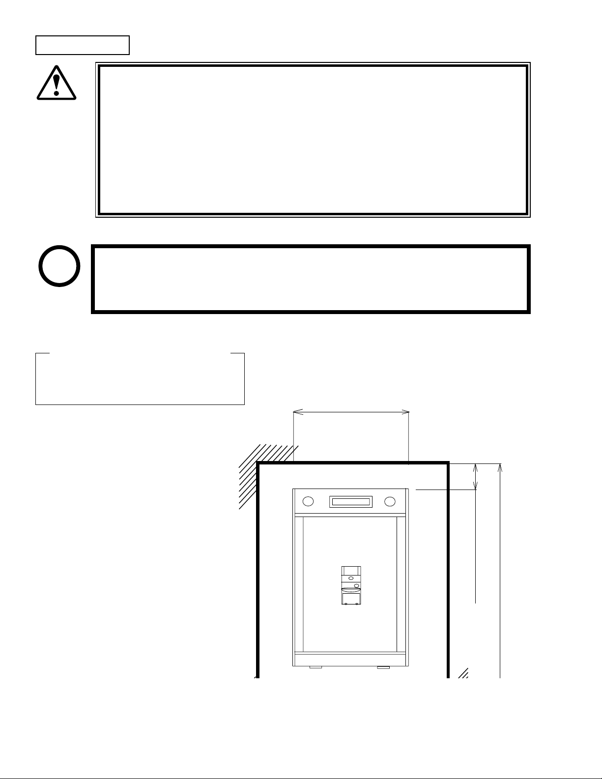
Operation Area
68 in.
Vent approx. 10 in.
36 in.
For the operation of this machine, secure a minimum area of 36 in. (W) × 68
WARNING!
Be sure to provide sufcient space so as to allow this product's ventilation fan
SEGA shall not be held responsible for damage, compensation for damage to a
in. (D). In order to prevent injury resulting from the falling down accident
during game play, be sure to secure the minimum area for operation.
to function efciently. To avoid machine malfunctioning and a re, do not
place any obstacles near the ventilation opening.
third party, resulting from the failure to observe this instruction.
STOP
For transporting the machine into the location's building, the minimum necessary
dimensions of the opening (of doors, etc.) are 37 in. (W) and 68 in. (H).
IMPORTANT!
Electric current consumption
MAX. ? A (AC 120 V 60 Hz)
www.seuservice.com
4
Page 13
3. OPERATION
PRECAUTIONS TO BE HEEDED BEFORE STARTING THE OPERATION
To avoid injury and trouble, be sure to constantly give careful attention to the behavior and manner
of the visitors and players.
In order to avoid accidents, check the following before starting the operation:
To ensure maximum safety for the players and the customers, ensure that where
WARNING!
the product is operated has sufcient lighting to allow any warnings to be read.
Operation under insufcient lighting can cause bodily contact with each other,
hitting accident, and or trouble between customers.
It is suggested to ensure a space allowing the players who feel sick while play-
ing the game to take a rest.
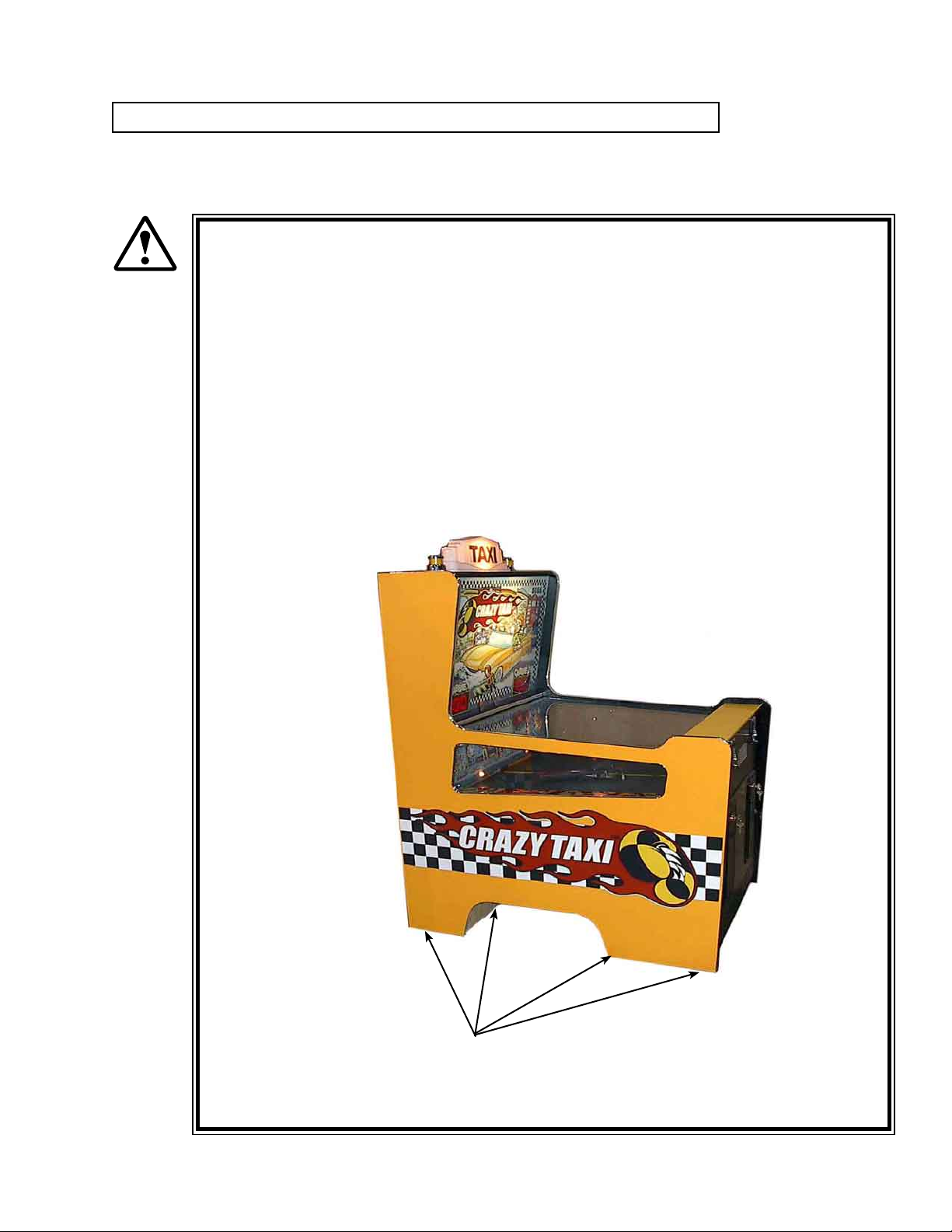
Check if all of the adjusters are in contact with the surface. If they are not, the
Cabinet may move and cause an accident.
Ensure that all of the Adjusters are in contact
with the oor.
5
www.seuservice.com
Page 14
7
www.seuservice.com
Immediately stop such violent acts as hitting and kicking the product. Such
violent acts can cause parts damage or falling down, resulting in injury due to
fragments and falling down.
CAUTION!
Do not put any heavy item on this product. Placing any heavy item on the prod-
uct can cause a falling down accident or parts damage.
WARNING!
PRECAUTIONS TO BE HEEDED DURING OPERATION (PAYING ATTENTION TO CUSTOMERS)
WARNING!
Do not climb on the product. Climbing on the product can cause falling down
accidents. To check the top portion of the product, use a step.
To avoid electric shock, check to see if door & cover parts are damaged or omit-
ted.
To avoid electric shock, short circuit and or parts damage, do not put the follow-
ing items on or in the periphery of the product.
Flower vases, owerpots, cups, water tanks, cosmetics, and receptacles/
containers/vessels containing chemicals and water.
To avoid injury and trouble, be sure to constantly give careful attention to the behavior and manner of the visitors and players.
To avoid injury and accidents, those who fall under the following categories are
not allowed to play the game.
• Those who have experienced muscle convulsion or loss of consciousness when playing video game, etc.
• Intoxicated persons.
• Persons whose act runs counter to the product's warning displays.
To avoid injury resulting from falling down and electric shock due to spilled
drinks, instruct the player not to place heavy items or drinks on the product.
To avoid electric shock and short circuit, do not allow customers to put hands
and ngers or extraneous matter in the openings of the product or small openings in or around the doors.
To avoid falling down and injury resulting from falling down, immediately stop
the customer's leaning against or climbing on the product, etc.
WARNING: HAZARD TO EPILEPTICS.
A very small portion of the population has a condition which may cause them to ex-
WARNING!
If you or anyone in your family has experienced symptoms linked to an epileptic
We recommend that parents observe their children while they play video games. If
www.seuservice.com
perience epileptic seizures or have momentary loss of consciousness when viewing
certain kinds of ashing lights or patterns that are present in our daily environment.
These persons may experience seizures while watching some kinds of television
pictures or playing certain video games. People who have not had any previous
seizures may nonetheless have an undetected epileptic condition.
condition (e.g., seizures or loss of awareness), immediately consult your physician
before using any video games.
you or your child experience the following symptoms: dizziness, altered vision, eye
or muscle twitching, involuntary movements, loss of awareness, disorientation, or
convulsions, DISCONTINUE USE IMMEDIATELY and consult your physician.
6
Page 15

4. ASSEMBLING AND INSTALLATION
Perform assembly work by following the procedure herein stated. Failing to
comply with the instructions can cause electric shock hazard.
WARNING!
Perform assembling as per this manual. Since this is a complex machine,
erroneous assembling can cause an electric shock, machine damage and or not
functioning as per specied performance.
When assembling, be sure to use more then one person. Depending on the
assembly work, there are some cases in which working by one person alone can
cause personal injury or parts damage.
Ensure that connectors are accurately connected. Incomplete connections can
cause electric shock hazard.
Be careful not to damage the wires. Damaged wires may cause electric shock or
short circuit or present a re risk.
This work should be performed by the Location's Maintenance Man or
Serviceman. Performing work by non-technical personnel can cause a severe
accident such as electric shock. Failing to comply with this instruction can cause
a severe accident such as electric shock to the player during operation.
Provide sufcient space so that assembling can be performed. Performing work
in places with narrow space or low ceiling may cause an accident and assembly
work to be difcult.
To perform work safely and avoid serious accident such as the cabinet's falling
down, do not perform work in places where step-like grade differences, a ditch,
or slope exist.
CAUTION!
Handle molded parts with care. Undue weight or pressure may cause them to
break and the broken pieces may cause injury.
To perform work safely and securely, be sure to prepare a step which is in a
secure and stable condition. Performing work without using the step can cause
violent falling down accidents.
Tools such as a Phillips type screwdriver are required for the assembly work.
TAMPERPROOF
Phillips type screwdriver
WRENCH
T-15 Torx 8/32 (1)
Tool (Included with Unit)
7
www.seuservice.com
Page 16

9
www.seuservice.com
Installing the Car
68 in.
Vent approx. 10 in.
36 in.
1- Remove car from packaging
inside game cabinet.
2- Attach Connector to base of car
and stuff into hole between front
wheels.
3- Remove red double sided tape
covers and place car on move ment rail. Press car down
rmly to be sure tape is secure.
FIG. 6. 2 e
Provide ventilation space for the ventilation
opening.
Allow more than 28 in. of space for customer
trafc.
www.seuservice.com
8
Page 17

POWER SUPPLY, AND EARTH CONNECTION
Be sure to independently use the power supply socket outlet equipped with
WARNING!
Ensure that the "accurately grounded indoor earth terminal" and the earth wire
Ensure that the power cord and earth wire are not exposed on the surface
After wiring power cord on the oor, be sure to protect the power cord. Exposed
an Earth Leakage Breaker. Using a power supply without an Earth Leakage
Breaker can cause a re when electric leakage occurs.
cable are available (except in the case where a power cord plug with earth is
used). This product is equipped with the earth terminal. Connect the earth
terminal and the indoor earth terminal with the prepared cable. If the grounding
work is not performed appropriately, customers can be subjected to an electric
shock, and the product's functioning may not be stable.
(passage, etc.). If exposed, they can be caught and are susceptible to damage. If
damaged, the cord and wire can cause electric shock and short circuit accidents.
Ensure that the wiring position is not in the customer's passage way or the wiring
has protective covering.
power cord is susceptible to damage and causes an electric shock accident.
The AC Unit is located inside on one side of Cabinet. The AC Unit has Main SW, Earth Terminal
and the Inlet which connects the Power Cord.
Ensure that the Main SW is OFF.
Back-Bottom Left of Cabinet
Power is off when the
MAIN SWitch is in the
down position. To supply
power to the unit, ip the
MAIN SWitch upwards.
* Note: Actual Power Supply connection
may vary from photo
MAIN SW
15A Rocker
INLET
AC Cable (Power Cord)
9
www.seuservice.com
Page 18

11
www.seuservice.com
5. PRECAUTIONS WHEN MOVING THE MACHINE
When moving the machine, be sure to unplug the power plug. Moving the
machine with the plug as is inserted can damage the power cord and cause re
WARNING!
and electric shock hazards.
When moving the machine on the oor, pay careful attention so that adjusters
do not tread power cords and earth wires. Damaging the power cords can cause
electric shock and short circuit hazards.
Do not push the cabinet from the left/right when attempting to move the unit.
Pushing from the sides may cause the unit to tip and result in injury and damage
to parts.
Do not push on any parts made of glass (e.g. Main Plex) or plastic, as these parts
may break and result in bodily injury.
CAUTION!
www.seuservice.com
10
Page 19

6. NAME OF PARTS
Yellow Lighted Thingie
Iluminated Marquee Thingie
Score/Ticket Display
Playeld
Coin Inlet
Taxi
Ticket
Despencer
Main Base
TABLE 1 Dimensions and Weights
Width x Length x Height Weight
CABINET 36 in x 48 in x 67 in 392 LBS
11
www.seuservice.com
Page 20

13
www.seuservice.com
7. GAME DESCRIPTION
The following explanations apply to cases where the product is functioning satisfactorily. Should
there be anything different then the following contents, some sort of faults may have occurred.
Immediately look into the cause of the fault and eliminate the cause thereof to ensure satiffactory
operation.
Connect the Power cord to an A/C source, turn on the power switch, then verify the following:
• lights illuminate inside the Taxi Dome
• lights illuminate behind the Marquee Glass
• lights blink behind the Prize Goal
• lights chase behind the people on the Panel Prize Plastic
• lights chase down the sides of the Play Field
• and lights illuminate the headlamps in the Taxi itself
At this time the ticket displays are lit with “100”’s and the taxi begins to move with it’s special
motion as well as sound emitted from the front speakers.
Lights are lit
Lights chase each other
Game Overview
Taxi moves from left to right
Sound is emitted
This game is a redemption game. Meaning that you input coins/tokens and after play it dispences
tickets to be redeemed for prizes. Coins/Tokens are inserted into the slots on the front then they
are rolled down the Play Field attempting to miss the Taxi and into the Prize Goal area. Depending
on which person is lit at the time the coin/token crosses that area is the amount of tickets that are
dispenced.
www.seuservice.com
12
Page 21

8. HOW TO PLAY
Play starts with the player inserting a coin/
token into a slot on the front of the machine.
This token is compaired with the token in the
compairitor and then released.
When this coin/token is released it starts its’
trip down the play eld. At this time it is possible for the “TAXI” to knock the coin/token
on its’ side causing a “loser” or it will nish
it’s travel in the “pick up zone”. If it fails to
reach the “pick up zone” and the game is set to
dispence “Mercy Tickets” they will be outputted at this time.
Insert Coin/Token
If the coin/token reaches the “pick up zone”
then depending on which “person” was lit on
the backboard then that amount is displayed on
the ticket display.
At this time tickets are dispenced in the
amount of what’s displayed on the ticket
display.
Coin Rolls down play eld
Tickets won are displayed
Tickets are dispenced
13
www.seuservice.com
Page 22

15
www.seuservice.com
9. Game Settings
Audit Switch 1
Note: Switches perform various functions
Audit Switch 2
Audit Switch 4
Audit Switch 3
When Player 1 is out of tickets, press AUDIT SWITCH 1. The game will then resume paying
out Player 1’s tickets.
When Player 2 is out of tickets, press AUDIT SWITCH 2. The game will then resume paying
out Player 2’s tickets.
When both sides of the game are in idle (nobody is playing), press AUDIT SWITCH 3 to enter
the SYSTEM menu. Both displays will show SYS. If the user presses AUDIT SWITCH 1,
the game will cycle backward through the menu below. If kthe user presses AUDIT SWITCH 2,
the game will cycle forward through the menu below.
1- SYS (for SYStem)
2- AUD (for AUDits)
3- ADJ (for ADJustments)
4- VOL (for VOLume)
5- END (for exit back to game play)
during each test.
The following sections will explain their use:
Press AUDIT SWITCH 4 to enter the mode on the display (either system, audits, volume, or end)
SYStem
For SYStem, the left display will show SYS. The right display will show the test number.
AUDIT SWITCH 4 will move from one test to the next.
1- SCORE 1 AC Lamp Flashing
2- SCORE 2 AC Lamp Flashing
3- SCORE 3 AC Lamp Flashing
4- SCORE 4 AC Lamp Flashing
5- SCORE 5 AC Lamp Flashing
6- SCORE 6 AC Lamp Flashing
7- SCORE 7 AC Lamp Flashing
8- SCORE 8 AC Lamp Flashing
9- SCORE 1 906 Lamp Flashing
10- SCORE 2 906 Lamp Flashing
11- SCORE 3 906 Lamp Flashing
12- SCORE 4 906 Lamp Flashing
13- SCORE 5 906 Lamp Flashing
14- SCORE 6 906 Lamp Flashing
15- SCORE 7 906 Lamp Flashing
www.seuservice.com
14
Page 23

16- SCORE 8 906 Lamp Flashing
17- WIN Light Player 1 Flash
18- WIN Light Player 2 Flash
19- GI Lamps Cycling
20- Left Turn Signal
21- Right Turn Signal
22- Opto Player 1 (Score Lamp 1 will be on if the switch is made, off is switch is open)
23- Opto Player 2 (Score Lamp 1 will be on if the switch is made, off is switch is open)
24- Coin Mech 1 (Score Lamp 1 will be on if the switch is made, off is switch is open)
25- Coin Mech 2 (Score Lamp 1 will be on if the switch is made, off is switch is open)
26- Left Limit Switch (Score Lamp 1 will be on if the switch is made, off is switch is open)
27- Right Light Switch (Score Lamp 1 will be on if the switch is made, off is switch is open)
28- Car Motor (Car Motor will run)
29- Shake Motor (Shake Motor will run)
Pressing AUDIT SWITCH 4 during test 29 will cause the game to go back to the main SYStem
Menu (at the END slot (“END” will be displayed)).
ADJustments
When “ADJ” is displayed to the left AUDIT SWITCH 1 will increase the adjustment value.
AUDIT SWITCH 2 will decrease the adjustment.
1- Win chance (10 ~ 30), default is 20
Pressing AUDIT SWITCH 4 will save the adjustment and return the game back to the
main SYStem menu (at the END slot (“END” will be displayed))
AUDits
When “AUD” is displayed to the left pressing AUDIT SWITCH 4 will advance to the next audit.
AUDIT SWITCH 3 will clear the current audit.
1- Total number or tickets (rolls over at 99,999)
2- Total number of coins (rolls over at 99,999)
3- Total number of Jackpots (rolls over at 999)
Pressing AUDIT SWITCH 4 during test 29 will cause the game to go back to the main SYStem
Menu (at the END slot (“END” will be displayed)).
VOLume
When “VOL” is displayed to the left pressing AUDIT SWITCH 4 will save the volume setting
and return the game back to the main SYStem menu at the “END” slot. Pressing AUDIT
SWITCH 1 will decrease the volume. Pressing AUDIT SWITCH 2 will increase the volume.
During VOLume, the game will have the drum track looping, changing volume as the user
presses AUDIT SWITCH 1 and AUDIT SWITCH 2.
END
Pressing AUDIT SWITCH 4 while “END” is displayed will Exit the Main SYStem menu and
return the game back to game play.
15
www.seuservice.com
Page 24

17
www.seuservice.com
10. Gameboard Cong Settings
Dip Switches
Jackpot
Dip1 Dip2
Off Off 50 Pt Jackpot
On Off 100 Pt Jackpot
Off On Progressing Jackpot
On On Progressing Jackpot
Dip Switches
Ticket Payout
Dip3
Off Normal Ticket Payout
On Two Point Ticket Payout
Mercy Tickets (Tickets Dispenced if coin fails to cross Opto. Sensors)
Dip4 Dip5
Off Off No Mercy Tickets
On Off 1 Mercy Ticket
Off On 2 Mercy Tickets
On On 3 Mercy Tickets
Game Difculty (Cycling Lamp Speed)
Dip6 Dip7
Off Off Fast
On Off Medium
Off On Slow
On On Really Slow
Dip8
Not Used
www.seuservice.com
16
Page 25

11. Game Error Codes
This game only has 1 error code which is CBO (which means that the cashbox switch is not set and the
game will not play when this switch is open and the error code is on the display).
Cashbox Switch
17
www.seuservice.com
Page 26

19
www.seuservice.com
12. TICKET DOOR
Ticket Door is a Happ Controls Part #40-0549-00 and comes with the Ticket Stickers Happ
Controls Part#42-1378-00
There is a ticket Meter in this game for an ongoing ticket count.
www.seuservice.com
18
Page 27

TICKET DISPENSER
19
www.seuservice.com
Page 28

www.seuservice.com
21
www.seuservice.com
20
Page 29

21
www.seuservice.com
Page 30

23
www.seuservice.com
P/N QTY DELTRONIC LABS P/N NAME
11 1 SHFT-IDLRLR/TD IDL. ROLLER SHAFT
12 1 RM-SFTMTR/TD MOTOR PIVOT SHAFT
13 1 SPAC PIVBLK/TD/4HOL PIVOT BRACKET SPAC
14 1 RM-SPCPB/TD SPACER BLOCK
15 2 RM-RLRIDL/TD/VALD IDLER ROLLER
16 1 RM-RLRDRV/TD/VALD DRIVER ROLLER
17 2 SPRG-TENSN/TD TENSION SPRING
18 2 RM-BKTPVT/TD BRAKE WHEEL
19 1 RM-PANLFT/TD/NOPM FRONT PANEL
20 1 RM-WHLBRK/TD BRAKE WHEEL
21 1 SPR-LOCA/TD LOCATING SPRING
22 1 RM-BRKTBRK/TD BRAKE BRACKET
23 1 RM-BKTTUB/TD/3/8 URETHANE BRAKE
24 1 PCBD-12275/TD PC BOARD
25 1 RM-MOTOR/TD MOTOR
26 2 RM-PLATFR/TD FRAME PLATE
27 1 RM-CONN2P/TE/20G 2-PIN FEMALE CONN.
28 4 BRNG-F312/TT/BRASS BUSHING
29 1 SPAC-PCBD/TD P.C. BOARD SPACER
30 1 SPAC/HEX/TD/1-1/4 HEX SPACER 1-1/4”
31 1 RM.1M/TT/50V .IMFD 50V
32 1 SPAC-HEX/TD/1/4” STAND OFF
33 1 GUID-BOTTOM/TD/MET LOWER GUIDE MET.
34 4 RING-E25RT/TT RETAINING RING
35 1 GUID-TOP/TD/MET GUIDE TOP METAL
36 2 PULY-SP212/TE/NYLN SPACER WASHER
37 2 SPRG-FRONTTP/TD SPRING FRONT-PLATE
38 4 RM-PEMNUT/TD/FRPL PEMNUT FRAME
39 2 RM-PEMNUT/TD/FRPN PEMNUT FRONT
40 1 COVR-H21A/TD/OPTO DUST COVER
41 1 CONN MOLEX/TD/4PM 4 WIRE MOLEX MA.
42 1 RM-LABEL/TD/ALUM LABEL ALUMINUM
43 WIRE-REDBLK/TD/MOTOR
44 2 SPAC-PIVBRK/TD/HEX SPACER 1/4” HEX
DETAILS OF PARTS
www.seuservice.com
22
Material List for Screws
P/N QTY PART # DESCRIPTION
1 11 EM-#4-40S/TD-1/4 4-40X1/4”SCREW
2 3 RM-#4-40R/TS-1/4 4-40X1/4”WASHER HEAD
3 2 RM-#4-40R/TD-1/2 4-40X1/2”WASHER HEAD
4 1 RM-#8SCRW/TD 8-33X1-1/4”
5 1 RM-#4FLTW/TT #4 FLAT WASHER
6 5 RM-#4SPSW/TT #4 SPLIT LOC. WASHER
7 2 RM-#4-40T/TD/1/8 PHILLIPS TRUSSHEAD
8 1 RM-#8STAR/TD #8 INT STAR WASHER
9 1 SCRW-SET/TT 8-32X3/16” SET SCREW
10 1 SCRW-SET/TD/BKWH 8-32 X 1/8 SET SCREW
Page 31

14. DESIGN RELATED PARTS
999-1636 Dome Taxi
999-1654 Decal TAXI Dome
999-1637 Glass marquee
999-1643 Underlay Marquee
999-1649 Decal Checker Stripe (CAR)
999-1650 Decal TAXI (CAR)
999-1651 Decal License Plate (CAR)
999-1646 Instruction Decal
999-1648 Decal SEGA Logo
999-1647 Decal Front Door
999-1652 Decal Left Side Cabinet
999-1653 Decal Right Side Cabinet
23
www.seuservice.com
Page 32

25
www.seuservice.com
15. PARTS
Rear Door Section (P 1/2)
21
7
8
6
3
5
12
9
10
11
4
www.seuservice.com
24
Page 33

Rear Door Section (P 2/2)
Item Num-
Part Number Description Picture
ber
1 Local Purchase Bulb CEC C906
2 Local Purchase
3 998-0180
Socket Base Wedge
CEC #4087-3
Board AC Driver
#237-0081-01
4 999-1630 Cashbox Switch
5 998-0181
CPU Board
#237-0252-02
Photo Not available at time of print.
Photo Not available at time of print.
Opto Kodenshi
6 998-0182
#PSS-S13 Match
Pair EM & RCVR
7 Local Purchase
Bulb Appliance
AC 40W 120V
8 Local Purchase Lamp Socket AC
9 999-0167
10 999-1627
11 999-1628
Leg Leveler
1/2-13 3” L
Transformer
MCI-4-06-8016
Transformer
MCI-4-06-8012
Photo Not available at time of print.
Photo Not available at time of print.
Photo Not available at time of print
Photo Not available at time of print
Photo Not available at time of print
12 999-0676
On-Off Switch
15A Rocker
25
Photo Not available at time of print
www.seuservice.com
Page 34

27
www.seuservice.com
Top Section (P 1/3)
3
2
1
4
5
6
7
16
22
24
10
23
15
182019
8
9
11
12
25
13
21
14
17
www.seuservice.com
26
Page 35

Top Section (P 2/3)
Item Num-
Part Number Description Picture
ber
1 999-1636 Dome Taxi
2 Local Purchase
Bulb Tubular
AC 40W 120V
3 Local Purchase Lamp Socket AC
4 999-1620 Light Tower Yellow
5 999-1669 Marquee Retainer Strip
6 999-1637 Marquee Glass
7 999-1634
Pickup Plex (numbers
and people)
8 999-1641 GOAL Pink Plex
9 999-1638 Side Window Plex
Photo Not available at time of print.
27
www.seuservice.com
Page 36

29
www.seuservice.com
Top Section (P 3/3)
Item Num-
Part Number Description Picture
ber
10 999-1633 Side Guard Right
11 999-1632 Side Guard Left
12 Local Purchase
Bulb 161 14V
Wedge Base
13 999-1673 Playeld
14 999-1674
Playeld Glass
Retainer
15 999-1676 Coin Chute
16 999-1635 Car Molded
17 999-1675
Playeld Glass
Retainer Holder
18 999-1640
Panel Coin Chute
Guide
19 999-1639 Cover Coin Chute
www.seuservice.com
28
Photo Not available at time of print.
Page 37

Top Section (P 3/3)
Item Num-
Part Number Description Picture
ber
20 999-1624 Speaker 4in 4ohm 30W
21 999-1670 Speaker Grill 4in
Lamp Headlight AC/
22 Local Purchase
DC White
Incandescent
Photo Not available at time of print.
23 999-1671 Coin Guard
24 999-1672 Playeld Glass Support
25 999-1644 Playeld Glass
Photo Not available at time of print.
29
www.seuservice.com
Page 38

31
www.seuservice.com
Marquee Internal (P 1/2)
1
3
2
www.seuservice.com
30
Page 39

Marquee Internal (P 2/2)
Item Num-
Part Number Description Picture
ber
1 Local Purchase
Lamp Fluorescent
15W 18in Coolwhite
2 998-0178 Board BLK Display
3 999-1642
Vent Grill 3in X 18”
Black PowderCoat
Photo Not available at time of print.
31
www.seuservice.com
Page 40

33
www.seuservice.com
Internal Devices (P 1/2)
5
2
( )
43
1
6
7
www.seuservice.com
32
Page 41

Internal Devices (P 2/2)
Item Num-
Part Number Description Picture
ber
1 998-0179 Audit Board
2 999-1679 Shaker Motor Assy.
3 999-1623 Shaker Motor
4 999-1677 Shaker Bracket
5 999-1678 Shaker Connector
6 999-1626
Deltronic Ticket
Dispenser
7 999-1629 Ticket Out Switch
Photo Not available at time of print.
Photo Not available at time of print.
33
www.seuservice.com
Page 42

35
www.seuservice.com
Car Motor Assy. (P 1/3)
12
1
11
2
4
7
8
10
3
www.seuservice.com
5
9
15
16
34
14
17
6
13
Page 43

Car Motor Assy. (P 2/3)
Item Num-
Part Number Description Picture
ber
1 998-1680 Plate Carriage Bottom
2 999-1681 Plate Carriage Top
3 999-1622 Motor
4 999-1687 Rod 9in
5 999-1682 Shaft Taxi Mover
6 999-1683 Arm Bracket
7 999-1685 Bracket S/A Car
8 999-1684
Bracket Main Car
Assy.
35
www.seuservice.com
Page 44

Car Motor Assy. (P 3/3)
Item Num-
Part Number Description Picture
ber
9 999-1686 Collar Shaft
10 999-1688 Wheel Motor
11 999-1689 Slide Spacer
12 999-1631
13 999-1690
Micro Switch
Car Motor
Washer OD=13mm
ID=6.75MM
14 999-1692 E-Ring 13mm
15 999-1691
Washer OD=19.25mm
ID=9mm
16 999-1693 E-Ring 25mm
17 999-1621 Motor Fan
www.seuservice.com
36
Page 45

Warranty
Your new Sega Product is covered for a period of 90 days from the date of shipment. This certies
that the Printed Circuit Boards, Power Supplies and Monitor are to be free of defects in workmanship or materials under normal operating conditions. This also certies that all Interactive Control
Assemblies are to be free from defects in workmanship and materials under normal operating conditions. No other product in this machine is hereby covered.
Sellers sole liability in the event a warranted part described above fails shall be, at its option, to replace or repair the defective part during the warranty period. For Warranty claims, contact your Sega
Distributor.
Should the Seller determine, by inspection that the product was caused by Accident, Misuse, Neglect, Alteration, Improper Repair, Installation or Testing, the warranty offered will be null and void.
Under no circumstances is the Seller responsible for any loss of prots, loss of use, or other damages.
This shall be the exclusive written Warranty of the original purchaser expressed in lieu of all other
warranties expressed or implied. Under no circumstance shall it extend beyond the period of time
listed above.
Page 46

SEGA AMUSEMENTS USA, INC.
 Loading...