

Page 1
MINI DX
OWNER’S MANUAL
PART NO. 999-0988
1st Printing
July 2000
Page 2

Warranty
Your new Sega Product is covered for a period of 90 days from the date of shipment. This certifies
that the Printed Circuit Boards, Power Supplies and Monitor are to be free of defects in workmanship or materials under normal operating conditions. This also certifies that all Interactive Control
Assemblies are to be free from defects in workmanship and materials under normal operating conditions. No other product in this machine is hereby covered.
Sellers sole liability in the event a warranted part described above fails shall be, at its option, to
replace or repair the defective part during the warranty period. For Warranty claims, contact your
Sega Distributor.
Should the Seller determine, by inspection that the product was caused by Accident, Misuse, Neglect, Alteration, Improper Repair, Installation or Testing, the warranty offered will be null and void.
Under no circumstances is the Seller responsible for any loss of profits, loss of use, or other damages.
This shall be the exclusive written Warranty of the original purchaser expressed in lieu of all other
warranties expressed or implied. Under no circumstance shall it extend beyond the period of time
listed above.
Page 3

TABLE OF CONTENTS 1-2
INTRODUCTION OF THE OWNER MANUAL 3
GENERAL PRECAUTIONS 4-5
1. Precautions to be Heeded for Operation 6-7
2. Name of Parts 8
3. Accessories 9-10
4. Assembly and Installation 11-16
A) Assembly of Cabinet 11
B) Securing in Place (Adjuster Adjustment) 12
C) Power Supply 13
D) Assembling Check 14-16
1) Memory Test
2) C.R.T. Test
3) Sound Test
4) Input Test
5) Output Test
5. Precautions to be Heeded When Moving the Machine 17
6. Contents of Game 18
7. How to Play 19-25
A) Select Screen 19-20
B) Courses and Vehicles 21
C) How to Operate 21-22
D) Game Screen 23
E) Game Over 23
F) Damage System 23
G) Name Entry 24
H) Continuous Play vs. Play 24
I) Password 25
J) Flow Chart 25
8. System Test Mode 26-41
8-1 Switch Unit and Coin Meter 27
8-2 System Test Mode 28-41
A) System Test Mode Menu 28
B) Ram Test 28
C) JVS Test 29
D) Sound Test 30
E) C.R.T. Test 30
F) System Assignments 31-32
G) Coin Assignments 33-37
H) Bookkeeping 38
I) Backup Ram Clear 39
J) Rombd Test 40
K) Clock Setting 41
L) Game Test Mode 41
1
Page 4

9. Game Test Mode 42-49
A) Game Menu 42
B) Input Test 43
C) Output Test 44
D) Game Assignments 45-46
E) Bookkeeping 47
F) Calibration Test 48
G) Backup Data Clear 49
H) Features 49
10. Control Panel 50-54
10-1 Removing the Control Panel 51
10-2 Volume Adjustment\Replacement 52-53
10-3 Greasing 54
11. Coin Selector 55-58
12. Monitor 59-61
12-1 Cautions and Warnings Concerning the Safety for Handling
the Monitors 59
12-2 Cautions to be Heeded When Cleaning the C.R.T. Surfaces 60
12-3 Adjustment Method 61
13. Replacing the Flourescent Lamps and Buttons 62
14. Periodic Inspection Table 63
15. Design Related Parts 64
Design Related Parts 64
16.Parts List 65-72
Switch Unit 65
Assembly AC Unit 66
Assembly Seat 67
Assembly Controller 68-69
Assembly Lever Mecha 70-71
Assembly Brake 72
17. Wire Color Table 73-74
Wiring Diagram 74
2
Page 5
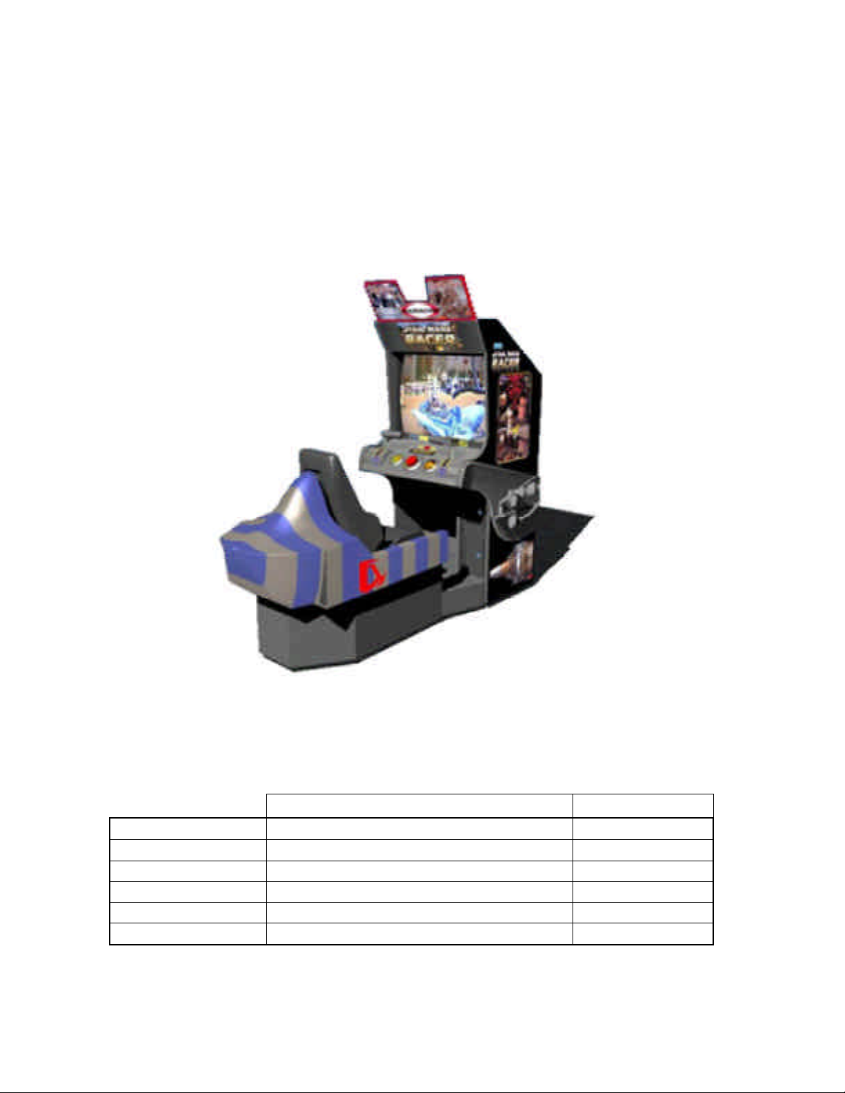
SPECIFICATIONS
Installation space: . 34 in.(L) x 87 in.(W)
Height: . 76 in.
Weight: Approx. 500 lbs.
Power maximum current: 6.8 Amp AC 120V 60 Hz
MONITOR: 33” COLOR MONITOR
INTRODUCTION OF THE OWNERS MANUAL
SEGA ENTERPRISES, LTD., has for more than 30 years been supplying various innovative and
popular amusement products to the world market. This Owners Manual is intended to provide
detailed descriptions together with all the necessary installation, game settings and parts ordering
information related to the STAR WARS RACER ARCADE, a new SEGA product.
This manual is intended for those who have knowledge of electricity and technical expertise, especially in ICs, CRTs, microprocessors, and circuit boards. Read this manual carefully to acquire
sufficient knowledge before working on the machine. Should there be a malfunction, nontechnical
personnel should under no circumstances touch the interior system. Should the need arise, contact
our main office, or the closest branch office listed below.
SEGA ENTERPRISES, INC. (USA)
Customer Service
45133 Industrial Drive
Fremont, CA 94538
Phone 415-701-6580
Fax 415-701-6594
7:30 am - 4:00 pm, Pacific Standard Time
Monday thru Friday
3
Page 6

General Precautions
Follow Instructions: All operating and use instructions should be followed.
Attachments: Do not use attachments not recommended by the product manufacturer as they may cause hazards.
Accessories: Do not place this product on an unstable cart, stand, tripod, bracket, or table. The product may fall,
causing serious injury to a child or adult, and serious damage to the product. Use only with a cart, stand, tripod, bracket, or
table recommended by the manufacturer, or sold with the product. Any mounting of the product should follow the
manufacturer’s instructions, and should use only mounting accessories recommended by the manufacturer.
Moving the Product: This product should be moved with care. Quick stops, excessive force, and uneven surfaces
may cause the product to overturn.
Ventilation: Slots and openings in the cabinet are provided for ventilation, to ensure reliable operation of the product
and to protect it from overheating; these openings must not be blocked or covered. The openings should never be blocked
by placing the product in a built-in installation such as a bookcase or rack unless proper ventilation is provided or the
manufacturer’s instructions have been adhered to.
Power Sources: This product should be operated only from the type of power source indicated on the marking label.
If you are not sure of the type of power supply to your location, consult your local power company. For products intended
to operate from battery power or other sources, refer to the operating instructions.
Grounding or Polarization: This product is equipped with a three-wire grounding-type plug, a plug having a third
(grounding) pin. This plug will only fit into a grounding-type power outlet. This is a safety feature. If you are unable to
insert the plug into the outlet, contact your electrician to replace your obsolete outlet. Do not defeat the safety purpose of the
grounding-type plug.
Power Cord Protection: Power-supply cords should be routed so that they are not likely to be walked on or pinched
by items placed upon or against them, paying particular attention to cords at plugs, convenience receptacles, and the point
where they exit from the product.
Overloading: Do not overload wall outlets, extension cords, or integral convenience receptacles as this can result in
a risk of fire or electric shock.
Object and Liquid Entry: Never push objects of any kind into this product through openings as they may touch
dangerous voltage points or short-out parts that could result in a fire or electric shock. Never spill liquid of any kind on the
product.
Servicing: Do not attempt to service this product yourself as opening or removing covers may expose you to danger-
ous voltage or other hazards. Refer all servicing to qualified service personnel.
Damage Requiring Service: Unplug this product from the wall outlet and refer servicing to qualified service person-
nel under the following conditions:
a) If the power cord or plug is damaged;
b) If liquid has been spilled, or objects have fallen into the product;
c) If the product has been exposed to rain or water;
d) If the product does not operate normally when following the operating instructions. Adjust only those controls that
are explained in the operating instructions. An improper adjustment of other controls may result in damage and will
often require extensive work by a qualified technician to restore the product to its normal operation;
e) If the product has been dropped or damaged in any way;
f) When the product exhibits a distinct change in performance; this indicates a need for service.
Replacement Parts: When replacement parts are required, be sure the service technician has used replacements parts
specified by the manufacturer or that have the same characteristics as the original part. Unauthorized substitutions may
result in fire, electric shock, or other hazards.
4
Page 7
Safety Check: Upon completion of any service or repairs to this product, ask the service technician to perform safety
checks to determine that the product is in proper operating condition.
Heat: The product should be situated away from heat sources such as radiators, heat registers, stoves, or other prod-
ucts (including amplifiers) that produce heat.
Lithium Battery- Dispose of batteries only in accordance with the battery manufacturer’s recommen-
dations. Do not dispose in an open flame condition, since the battery may explode.
Cleaning: When cleaning the monitor glass, use water or glass cleaner and a soft cloth. Do not apply chemicals such
as benzine, thinner, etc.
Location: This an indoor game machine, DO NOT install it outside. To ensure proper usage, avoid installing indoors
in the places mentioned below:
• Places subject to rain/water leakage, or condensation due to humidity;
• In close proximity to a potential wet area;
• Locations receiving direct sunlight;
• Places close to heating units or hot air;
• In the vicinity of highly inflammable/volatile chemicals or hazardous matter;
• On sloped surfaces;
• In the vicinity of emergency response facilities such as fire exits and fire extinguishers;
• Places subject to any type of violent impact;
• Dusty places.
INSTALLATION PRECAUTIONS
• Verify the amperage of the branch circuit outlet before plugging in the power plug. Do not overload the circuit.
• Avoid using an extension cord. If one is required, use an extension cord of type SJT, 16/3 AWG
rated min. 120 VAC, 7A.
• Moving this unit requires a minimum clearance (of doors, etc.) of 32” (W) by 77” (H).
• For the operation of this machine, secure a minimum area of 32” (W) by 42”(D).
REGULATORY APPROVALS
This game has been tested and found to comply with the Federal Communications Commission Rules.
This device complies with Part 15 of the FCC Rules. Operation is subject to the following two conditions: (1) This
device may not cause harmful interference, and (2) this device must accept any interference received, including interference
that may cause undesired operation.
This game has been tested and listed by Underwriters Laboratories, Inc., to ANSI/UL22.
5
Page 8
1 . PRECAUTIONS TO BE HEEDED FOR OPERATION
In order to prevent accidents, be sure to comply with the following points before and during operation.
PRECAUTIONS TO BE HEEDED FOR OPERATION BEFORE STARTING THE OPERATION
In order to avoid accidents, check the following before starting the operation:
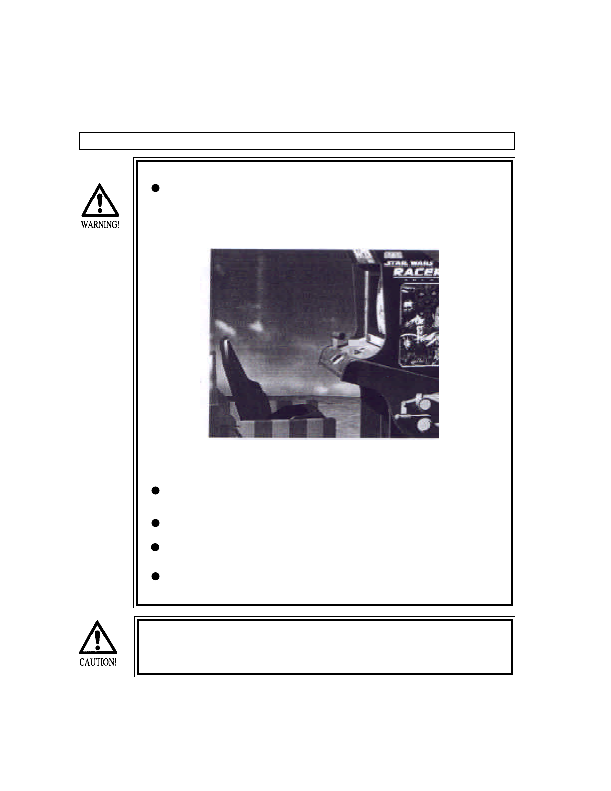
Check if all of the adjusters are in contact with the surface. If they are not,
the cabinet can move and cause an accident.
Do not climb on the product. Climbing on the product can cause falling down
accidents. To check the top portion of the product, use a step.
To avoid electric shock, check to see if door & cover parts are 508.5
To avoid electric shock, short circuit and or parts damage, do not put the
following items on or in the periphery of the product:
Flower vases, flower pots, cups, water tanks, cosmetics, and receptacles/
containers/vessels containing chemicals and water.
To avoid injury, be sure to provide sufficient space by considering the
potentially crowded situation at the installation location. Insufficient installation space can cause the player to come into contact with or hit others
and result in injury or trouble.
6
Page 9
PRECAUTIONS TO BE HEEDED DURING OPERATION
To avoid injury and accidents, those who fall under the following categories are not
allowed to play the game:
* Intoxicated persons
* Those who have high blood pressure or heart problems.
* Those who have experienced muscle convulsion or loss of consciousness when
playing video games, etc.
* Persons susceptible to motion sickness.
* Persons whose acts runs counter to the products warning displays.
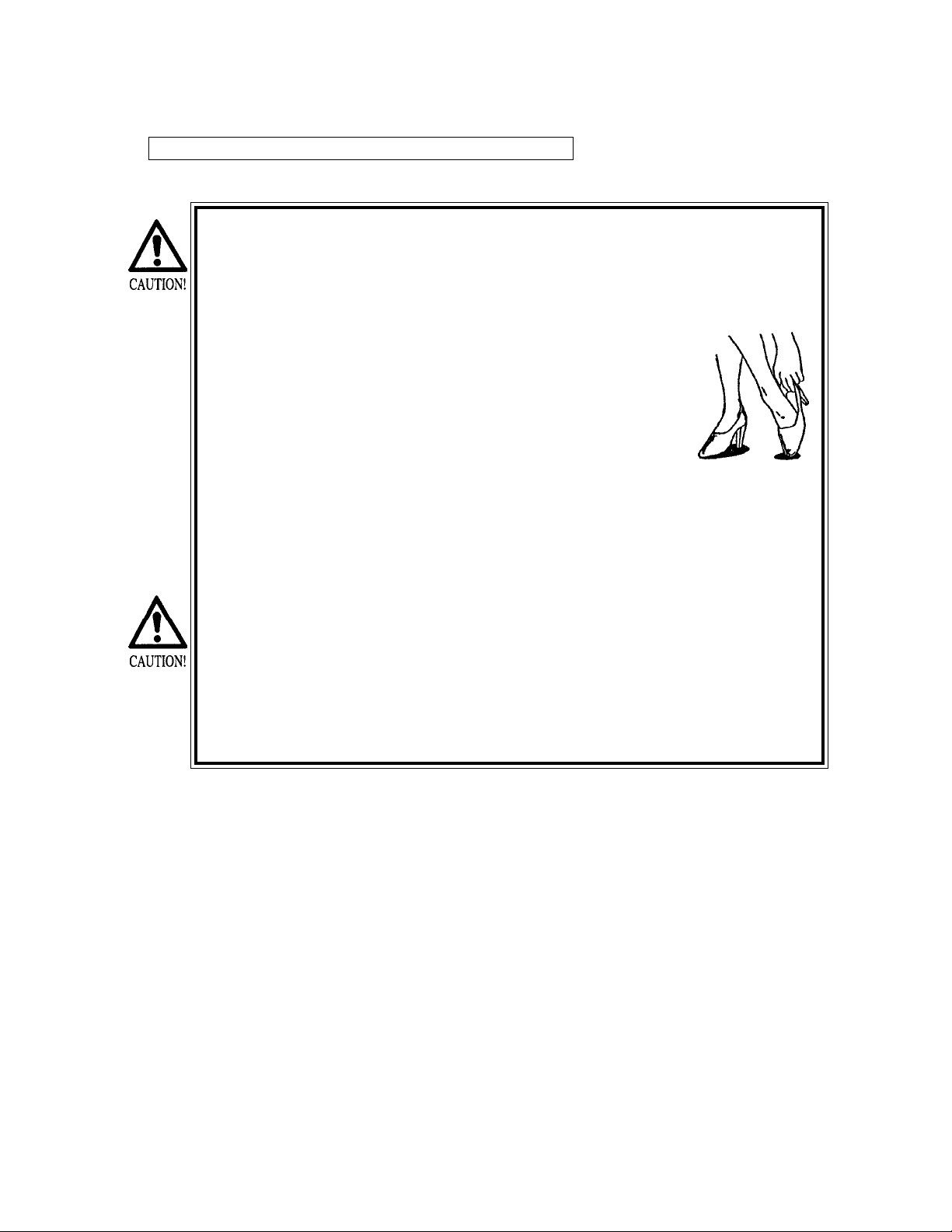
* Instruct those who wear high-heeled shoes to refrain from
playing the game by explaining that playing the game with high heeled shoes is very dangerous and likely to cause a
potentially hazardous situation.
• To avoid electric shock and short circuit, do not allow customers to put hands and
fingers or extraneous matter in openings of the product or small openings in or
around doors.
• To avoid electric shock circuit, do not allow the customers to unplug the power plug
without a justifiable reason.
• Although this product has the accident preventive covering attached to potentially
hazardous places where hand and fingers could be caught, small children are unable
to perceive hazards. Use care so that small children do not come close to the
product when in play.
• Immediately stop such violent acts as hitting and kicking the product. Such violent
acts can cause parts damage and /or falling down, resulting in injury due to
fragments and falling down.
7
Page 10
2. NAME OF PARTS
GAME SPECIFICATIONS
DURING SHIPPING Shipping dimensions currently unavailable
CABINET
SEAT CABI
WHEN ASSEMBLED
WIDTH LENGTH HEIGHT WEIGHT
34” X 87” X 76” 500 LBS
8
Page 11
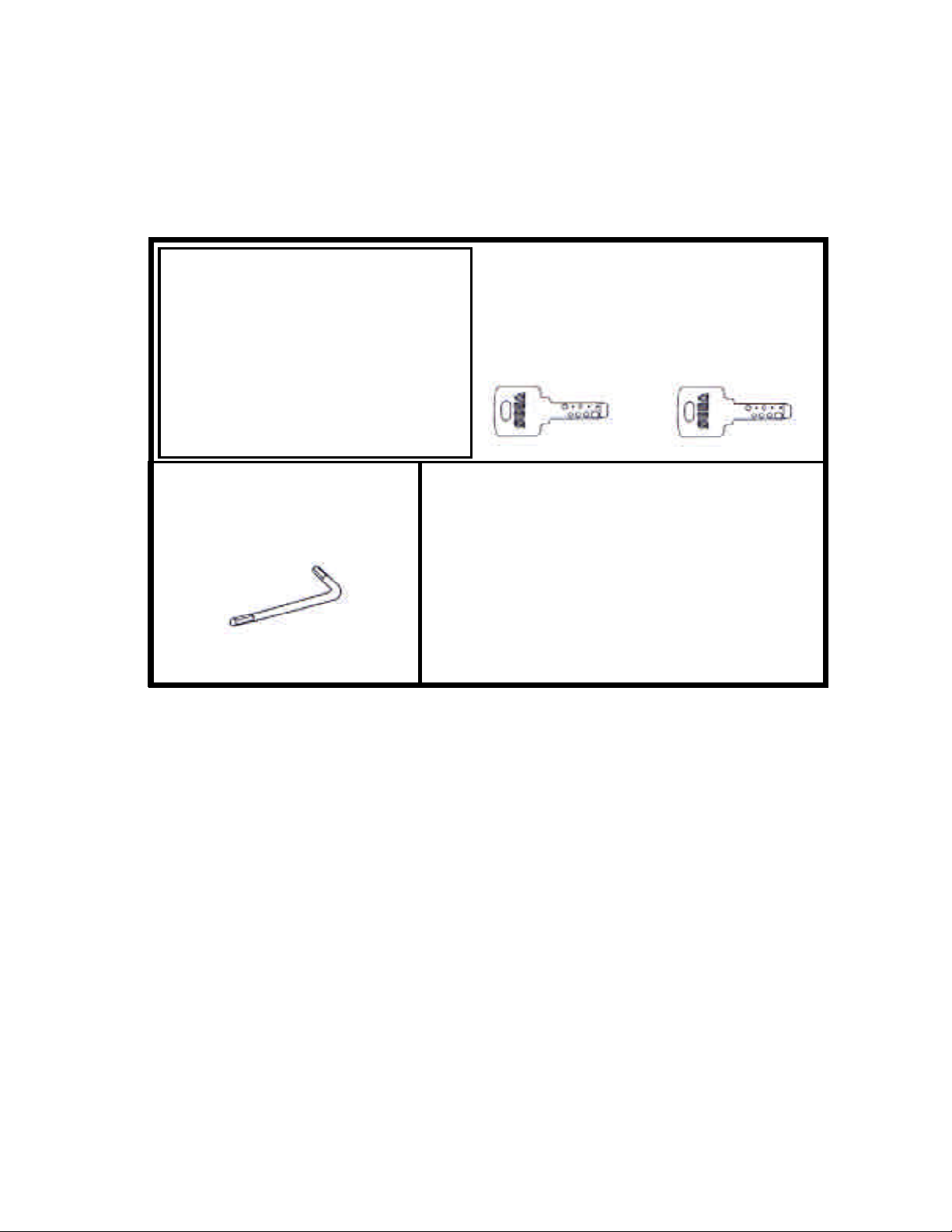
3. ACCESSORIES
DESCRIPTION OWNERS MANUAL
Part No. (Qty.) 999-0921
Note
Figures
If Part No. has no description, the Number has not
been registered or can not be registered. Such a
part may not be obtainable even if the customer
desires to purchase it. Therefore, ensure that the
part is in safekeeping with you.
TAMPERPROOF WRENCH
M8 540-0009-01 (1)
TOOL
KEY MASTER
220-5576 (2)
For opening/closing
the doors
KEY
(2)
For the CASHBOX DOOR
9
Page 12

THE SHIPMENT METHOD DESCRIBED BELOW ONLY
APPLIES TO ‘HIKARU’ BOARDS CONTAINED IN THE
FOLLOWING GAMES:
LOST WORLD, VIRTUA FIGHTER 3, SUPER GT, SEGA BASS FISHING, STRIKER 2
HARLEY DAVIDSON, STAR WARS RACER
!!!!NNEEVVEERR SSHHIIPP HHIIKKAARRUU GGAAMMEE BBOOAARRDDS
OOUUTTSSIIDDEE OOFF CCAAGGEE!!!
CARTON BOX
601-8928 (1)
Used for transporting the GAME BOARD.
{SUPPLIED WITH YOUR GAME}
DO NOT SHIP GAME BOARD WITHOUT
THIS BOX AS IT MAY DAMAGE THE GAME
BOARD AND VOID YOUR WARRANTY.
“CHECK SIDE” Display
!
FILTER BOARD
S
NO OTHER GAMES BOARDS ARE TO BE SHIPPED IN THE CAGE AS
THEY MAY BE DAMAGED BEYOND REPAIR. PLEASE SHIP THEM
WITHOUT CAGE PROPERLY PROTECTED DURING SHIPPING.
10
Page 13
4 . ASSEMBLING AND INSTALLATION
Assembling should be performed as per this manual. Since this is a
complex machine, erroneous assembling may cause damage to the
machine, or malfunctioning to occur.
When assembling, be sure to perform work by plural persons.
Depending on the type of work, there are some cases in which a
single person performing the work can cause personal injury or parts
damage.
When carrying out the assembly work, follow the procedure in the following 4-item sequence:
1
ASSY OF CABINET
2
SECURING IN PLACE (ADJUSTER ADJUSTMENT)
POWER SUPPLY
3
ASSEMBLING CHECK
4
Note that tools such as a phillips-head screwdriver and wrench for M16 hexagon bolt w/24 mm
width across flats are required for the assembly work.
ASSY OF CABINET
A
Permanantly tightening the hex bolts should not be completed until
the leg levelers are adjusted properly.
11
Page 14
B
1
2
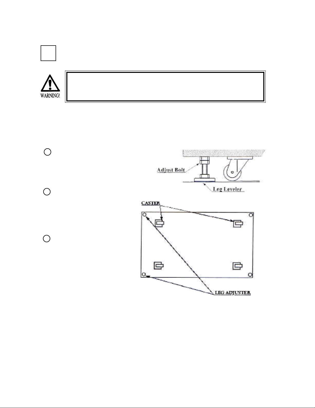
SECURING IN PLACE (ADJUSTER ADJUSTMENT)
Be sure to have all the Adjusters make contact with a flat surface.
Unless the Adjusters come into contact with a flat surface, the Cabinet can move of itself, causing an accident.
This machine has 4 casters and 4 adjusters (shown below). When the installation position is determined, make sure
that the machine position is level, bring the adjusters into direct contact with the floor, and make adjustments so that
the casters will be raised approximately 5mm. from the floor.
Move the machine to the installation
position. Be sure to provide adequate
space allowing the player to get on
and off.
Have all of the leg adjusters make
contact with the floor. Adjust the
height of the leg adjusters by using a
wrench so that the machine’s position
is kept level.
After making adjustments, fasten the
3
leg adjuster nut upward and secure
the height of the leg adjuster.
12
Page 15
C
POWER SUPPLY
Ensure that the power cord is not exposed on the surface (passage,
etc.). If exposed, they can be caught and are susceptible to
damage. If damaged, the cord can cause an electric shock or short
circuit.
Ensure that the writing position is not in the customer’s passage
way or the wiring has protective covering.
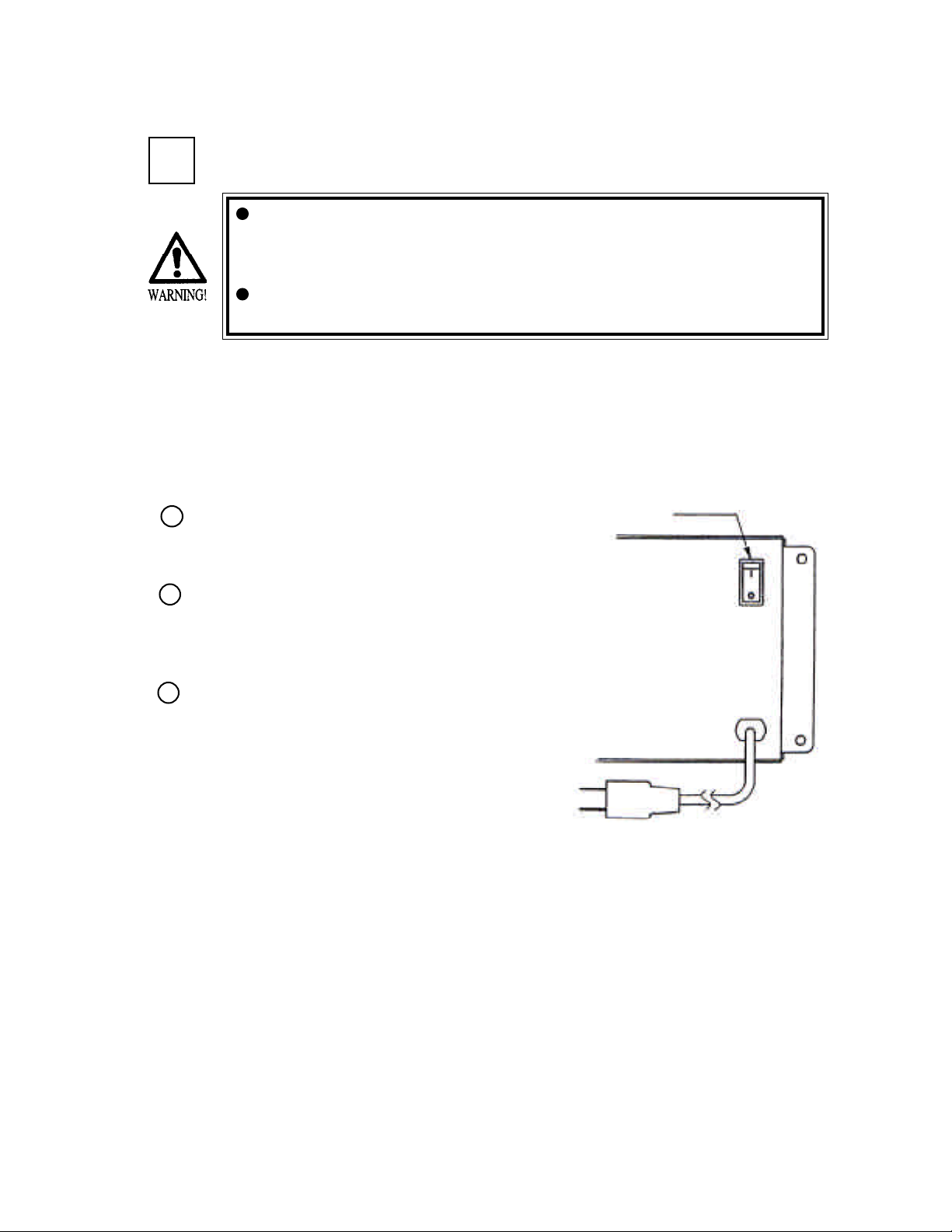
Connet the game to the power supply and turn on power to the game. Before connecting power
supply be sure that power switch if off.
1
Turning the AC unit’s main switch on will cause the
machine to start the power check and network check
automatically.
2
In the Power On check, the steering wheel turns left
and right, and then returns to the centering position
and stops. In this check, the values of the VR inside
the control panel are corrected.
3
Until this check is finished, and the steering wheel
stops do not touch the steering wheel or play the
game.
If you do, the steering reaction during the game
(reaction at the time of course-out or crash) can not
be obtained correctly. In the case of an abnormal
reaction during the game, turn power on again from
the beginning and complete the power on check.
MAIN SW
To the Power Supply
Socket outlet
13
Page 16
D
ASSEMBLING CHECK
In the TEST MODE, ascertain that the assembly has been made correctly and IC BD, is
satisfactory (refer to Section 9).
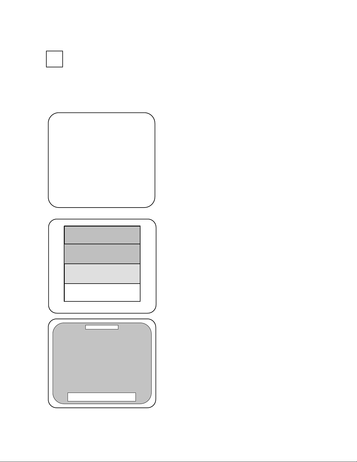
In the test mode, perform the following test:
(1) MEMORY TEST
RAM TEST
IC15 IC16 IC17S IC18S GOOD
IC22 IC23 IC24S IC25S GOOD
IC28 IC29S GOOD
IC41 GOOD
IC42 GOOD
IC44 IC45S IC46 IC47S GOOD
IC91S IC92S GOOD
IC98 GOOD
OPTIONAL SOUND BOARD:
IC12 GOOD
OPTIONAL COMMUNICATION BOARD:
IC7 IC8 IC9 IC10 GOOD
.
.
.
PRESS TEST BUTTON TO EXIT
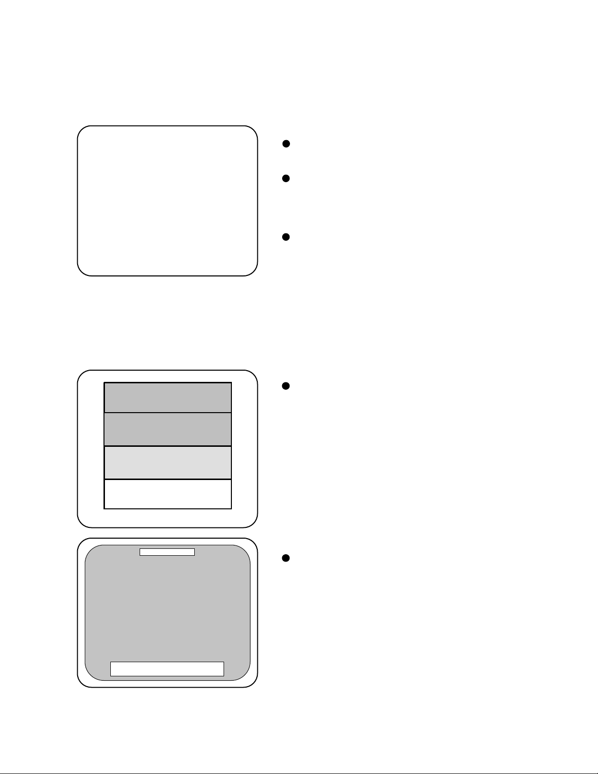
(2) C.R.T. TEST
0 31
C.R.T. TEST PAGE#1
Selecting the RAM TEST on the system test
mode menu screen causes the on-board
memory to be tested automatically. The game
board is satisfactory if the display beside each
IC No. shows GOOD.
RED
GREEN
BLUE
WHITE
PRESS SERVICE BUTTON TO ANOTHER PAGE
PRESS TEST BUTTON TO EXIT
C.R.T. TEST PAGE#2
PRESS SERVICE BUTTON TO ANOTHER PAGE
PRESS TEST BUTTON TO EXIT
In the system test mode menu, selecting C.R.T.
TEST allows the screen (on which the monitor
is tested) to be displayed.
14
Page 17
(3) SOUND TEST
SOUND TEST
MAIN SPEAKER LEFT
MAIN SPEAKER RIGHT
OPTION SPEAKER LEFT
OPTION SPEAKER RIGHT
>EXIT
SELECT WITH SERVICE BUTTON
AND
PRESS TEST BUTTON
(4) INPUT TEST
INPUT TEST
BOOST OFF
BRAKE OFF
LEFT BUTTON OFF
RIGHT BUTTON OFF
LEFT LEVER 3E
RIGHT LEVER 3D
START OFF
SERVICE OFF
TEST OFF
In the system test mode, selecting SOUND
TEST causes the screen (on which sound
related BD and wiring connections are
tested) to be displayed.
Check if the sound is satisfactorily emitted
from each speaker and the sound volume is
appropriate.
Selecting the INPUT TEST on the game test
mode menu screen causes the screen (on
which each switch is tested) to be displayed.
Press each switch. For the coin switch test,
insert a coin from the coin inlet with the coin
chute door open. If the display beside each
switch indicates “ON,” the switch and wiring
connections are satisfactory.
PRESS TEST AND SERVICE BUTTON TO EXIT
JVS TEST
> DISPLAY CONFIG
EXIT
NODE 1/1
SWITCH
SYSTEM ------------ PLAYER1 --------------------------- PLAYER2 ---------------------------COIN
SLOT1 0000 SLOT2 8000
ANALOG
CH1 6300 CH2 5A00 CH3 7D00 CH4 8100
CH5 1F00 CH6 1D00 CH7 1F00 CH8 2000
SELECT WITH SERVICE BUTTON
AND
PRESS TEST BUTTON
15
Page 18

(5) OUTPUT TEST
OUTPUT TEST
START LAMP OFF
BOOST LAMP OFF
BOOST LOCK OFF
>EXIT
SELECT WITH SERVICE BUTTON
AND
PRESS TEST BUTTON
Perform the above imspections also at the time of monthly inspection.
Select OUTPUT TEST from the Menu
screen in the Game Test Mode to cause the
screen (on which output unit such as lamps
and wiring connections are tested) to appear.
Ensure that the output unit functions
satisfactorily.
16
Page 19
5 . PRECAUTIONS TO BE HEEDED WHEN MOVING THE MACHINE
When moving the machine, be sure to unplug the power plug.
Moving the machine with the plug as is inserted can damage
the power cord and cause fire and electric shock hazards.
When moving the machine on the floor, retract the Adjusters
and ensure that Casters make contact with the floor. During
transportation, pay careful attention so that Casters do not
tread power cords. Damaging the power cords can cause an
electric shock and/or short circuit.
When lifting the cabinet, be sure to hold the catch portions or
bottom part. Lifting the cabinet by holding other portions can
damage parts and installation portions, due to the empty
weight of the cabinet, and cause personal injury.
Do not insert the fork to places other than designated when
using a Forklift to transport the machine.
Failure to observe this could cause falling down and injury
resulting from falling down.
Do not push the plastic made parts. Failure to observe this may
damage parts and cause injury due to fragments resulting from
damage.
When transporting the product in places with steps,
disassemble into each unit before transporting. Inclining the
product in an as is assembled condition or placing the
cabinet in places with steps can damage the unit’s joining
portions.
To protect surface, do not directly apply a rope to the
surfaces of product. Use protective materials to the places
the rope is applied to.
17
Page 20
6. CONTENTS OF GAME
The following explanations apply in the event the product is functioning satisfactorily.
Should there be any moves different from the following contents, some sort of fault may
have occurred. Immediately look into the cause of the fault and eliminate it to ensure
satisfactory operation.
When the product is energized, the Billboard’s fluorescent lamp is always lit. During the
advertise mode, the advertise screen is shown on the monitor and sound is emitted from the
speakers in the front, left and right of the seat. Setting to No Sound Output during the
advertise is possible in the TEST mode. During the advertise mode, the button on the
Control Panel is unlit.
18
Page 21
7.
HOW TO PLAY
To adjust the seat position, pull the lever under the seat on the right-hand side to release the
seat lock, and slide the seat forward or backward to the desired position.
The game starts upon inserting the required number of coins for one play.
(A) SELECT
SCREEN
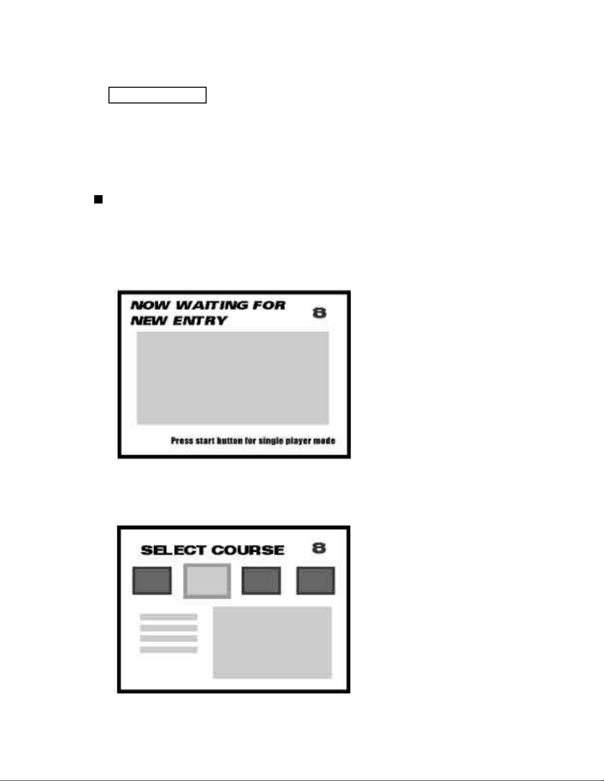
For Communication Play:
When in communication play, the monitor screen remains stationary for approximately 10
seconds to wait for the participant. The time limit is displayed in the upper right corner of the
screen. Press the START button to cancel vs. play and proceed to the 1P mode. To avoid
misoperation, pressing the START button will not cancel vs. mode during the first 3 seconds.
Use the SELECT button to choose one of the 4 courses and press the START button to decide.
The time limit for selecting the course is displayed in the upper right corner of the screen. The
course displayed on the left is easier, and the difficulty increases upon proceeding to the right.
19
Page 22
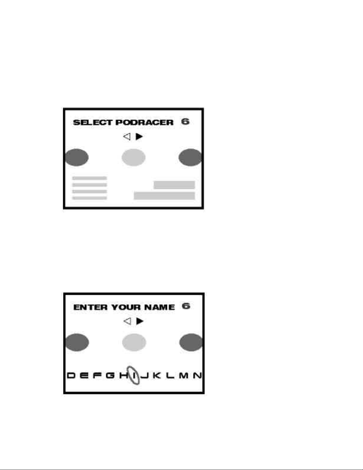
Use the SELECT button to choose one of the 4 vehicles and press the START button to
decide. The time limit for selecting the vehicle is displayed in the upper right corner of the
screen. At the time of shipment, only 2 of the vehicles are usable. However, by fulfilling the
requirements described later in this manual, the remaining 2 vehicles will become available.
The performance of each vehicle differs.
For Communication Play:
After selecting your vehicle, input your “name” using 3 letters. This name is displayed at the
top of the opponent’s vehicle in the game screen. Use the SELECT button to scroll through
the letters and press the START button to decide. Finally, select END to confirm. The time
limit for inputting your name is displayed in the upper right corner of the screen. Upon
completion of this process by all players, the game proceeds to the next screen.
While loading the game data, the screen remains stationary for a while. You cannot skip this screen.
20
Page 23
(B) COURSES AND VEHICLES
There are 4 courses in this product.
[BANTHA TRACKS] EASY
The actual course shown in the motion picture has been simplified and shortened for
beginners. Huge rocks rise out of the stretched wilderness.
[SMUGGLER’S COVE] NORMAL
A beautiful shoal and moss-covered land can be seen in this course. Although you will
face consecutive curves in the course, the difficulty itself is not too high.
[PIXELITO CHALLENGE] HARD
This course is staged in the mountains at night. The narrower road and the number of
hairpin curves make it the most difficult among the 4 courses in terms of the course
layout.
[THE BOONTA CLASSIC] EXPERT
Tthis course is a reproduction of the course shown in the motion picture . This course is
longer than the other 3 courses, making it difficult to stay the course.
There are 4 vehicles to choose from. The vehicles available at the beginning are the
ANAKIN SKYWALKER and the SEBULBA. The other 2 can only be used if certain
requirements are fulfilled.
Conditions to have the Hidden vehicles appear:
[GASGANO] Must exceed 700 plays total (with any course/character).
[BEN QUADINAROS] In the EXPERT course, game must be completed 50 times (with
any character).
*Note that once the vehicles appear, they will not be cleared when the BACKUP RAM
CLEAR is performed.
(C) HOW TO OPERATE
THROTTLE LEVER
(ACCELERATOR)
BOOST BUTTON
SELECT BUTTON
BRAKE LEVER
THROTTLE LEVER
(ACCELERATOR)
SELECT BUTTON
START BUTTON
DECIDE/VIEW CHANGE
21
Page 24
The THROTTLE LEVER left & right also function as an accelerator and steering. Incline the
THROTTLE LEVER forward to gain speed. To reduce the speed, pull the THROTTLE LEVER
toward you. Incline the right Lever forward and pull the left Lever toward you to turn left. Grip the
Brake Lever on the right-hand Lever to quickly reduce the speed. The Brake Lever itself is in the
digital switch system, however, braking power varies in accordance with the strength of gripping the
Lever.
Press the BOOST button on the center of the panel to gain a rapid speed for a certain period of time.
The gauge displayed at the lower right screen shows the current BOOST effect. The BOOST power
gradually diminishes, and when it becomes zero, acceleration is finished. While the BOOST is in
effect, the button is kept pressed down. Once the BOOST becomes active, the button returns to its
original state.
Note that setting of not performing the aforementioned operation can be selected.
In that case however, gaining a rapid speed by the BOOST button remains unchanged.
BOOST can be used up to 3 times per race. The BOOST button goes on when active, flashes during
use, and goes off when inactive.
The START button can be used for “DECIDE” in the select screen and “VIEW CHANGE” during
game. It goes on during the race only.
Use the SELECT button for selecting the course, the vehicle, and the letters in the NAME entry.
BRAKE and LEVER
used jointly
BRAKE and LEVER
used jointly
OPERATION - EFFECT of the LEVER
22
Page 25

(D) GAME SCREEN
PositionDuring communication play:
your position/total numbers of vehicles in play
During single play mode:
your position
Total time & Lap time
Engine damage gauge
Time remaining
Lap Counter (Displays the lap)
BOOST remaining
The rival position marker
during communication play
(E) GAME OVER
The purpose is to finish the predetermined number of laps within the time limit.
There are 3 laps in the EXPERT course and 4 in the other courses. When the remaining time
becomes zero, you have to retire unfinished. Pass through the checkpoints on the course, and
you can get extra time. When the first position player goes through the checkpoint, extra time
is given to other players. The same applies to communication play.
(F) DAMAGE SYSTEM
When hitting or making contact with obstacles, damage increases and the gauge displayed at
the lower left screen turns yellow. Recovery is possible if you do not hit or make contact with
them thereafter. When damage reaches the maximum, the gauge turns red and BOOST
cannot be used due to the limitation applied to the maximum speed. The condition can
automatically be restored, however, it takes approximately 10 seconds to do so.
Damage warning lamp
Current speed
Speed meter & BOOST
time remaining
23
Page 26

(G) NAME ENTRY
The NAME ENTRY screen where you can input your name up to 3 letters will be displayed
on the following conditions:
(1) In 1P mode, when the player’s record is excellent. (after race)
(2) In 1P mode, when the player is finished within the first to the third position. (after race)
(3) Communication (vs.) play is formed. (before race)
Scroll the letter screen with the SELECT button and press the START button to decide. After
inputting the 3 letters, bring the cursor to “END” and press the START button to decide.
In case of (1) as above, after the name entry, the rank will be displayed.
In case of (2) as above, the name entry is for making password for the Internet ranking
registration. Therefore, the name will not necessarily be displayed for in-game ranking.
(H) CONTINUOUS VS. PLAY
In vs. play, while the game over screen is displayed, you are asked if you continue vs. play.
The countdown is displayed at the same time. If 2 or more players insert coins before countdown reaches zero, continuous vs. play is effective, and vs. play record in total is displayed.
Note that “P1~P4” as above displays the seat numbers set in the TEST MODE.
24
Page 27

(I) PASSWORD
When you succeed to run the whole distance in 1P mode in any course, the password screen
will be displayed. Make a note of the password shown in the screen and send it to the Home
Page exclusive for this game, and you can enter in the world ranking register. You can skip
this screen by pressing the START button. The Home Page will be open in May 2000. Operation and maintenance in the second year and thereafter are undecided, however.
URL: http://www.sega.co.jp/racer/
(J) FLOW CHART
Waiting for a participant
Course select
POD select
For communication vs. play
Name entry
Game
Result
Game over
Finished the EXPERT course
in the 1st position in 1P play
End credit
Finished within the 3rd position
in 1P play, or
In case of RANK-IN
Name entry
Rank display
Password display
When finishing the
game within the 3rd
position in the single
mode.
You can skip the items enclosed with a dotted line in the above chart with the START button.
25
Page 28

SYSTEM TEST MODE
8 .
• The contents of settings changed in the TEST mode are stored when the TEST
mode is finished from EXIT in the MENU mode. If the power is turned off before
the TEST mode is finished, the contents of the setting changes do not take effect.
• Executing “BACKUP DATA CLEAR” in the SYSTEM TEST MODE does not clear the
BOOKKEEPING data in the GAME TEST MODE.
• Entering the TEST mode clears fractional numbers of coins less than one credit
and BONUS ADDER data.
The SYSTEM TEST mode mainly allows checks of the IC Board for accurate functioning , monitor adjustment, as well
as CRT TEST and COIN ASSIGNMENTS, etc. The following assignments, however, should be designated for this
product.
♦ CABINET TYPE : 1 PLAYER (S)
♦ MONITOR TYPE : HORIZONTAL
♦ SERVICE TYPE : COMMON
♦ COIN CHUTE TYPE : COMMON
TEST ITEM SELECT
SYSTEM MENU
RAM TEST
JVS TEST
SOUND TEST
C.R.T. TEST
SYSTEM ASSIGNMENTS
COIN ASSIGNMENTS
BOOKKEEPING
BACKUP DATA CLEAR
ROMBD TEST
CLOCK SETTING
ROM BOARD TEST
GAME TEST MODE
-> EXIT
SELECT WITH SERVICE BUTTON
AND PRESS TEST BUTTON
1
After turning the power on, press the TEST button to display the test item menu shown above.
2
Press the SERVICE button to move the arrow to the desired item and press the TEST button.
When finished, bring the arrow to EXIT and press the TEST button to return to the Game mode.
3
26
Page 29

8 - 1 SWITCH UNIT AND COIN METER
Never touch places other than those specified. Touching places not
specified can cause electric shock and short circuit.
Adjust to the optimum sound volume by considering the environmental
requirements of the installation location.
If the COIN METER and the game board are electrically disconnected,
game play is not possible.
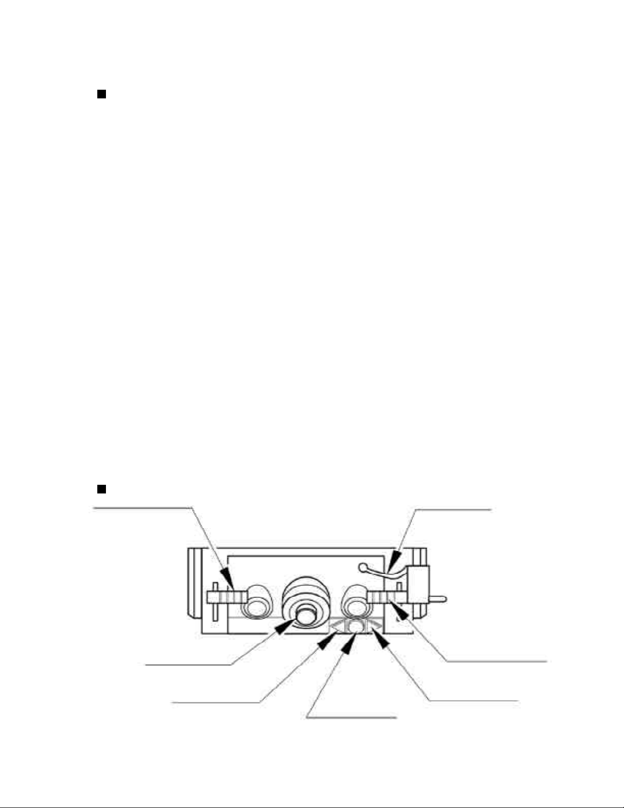
Open the COIN CHUTE DOOR, and the switch unit shown will appear. The
function of each switch is as follows:
SPEAKER VOLUME
SWITCH UNIT
For SUPER WOOFER
TEST BUTTON
SERVICE BUTTON
SPEAKER VOLUME
For SPEAKERS at the
CONTROL PANEL left &
right
SWITCH UNIT
SPEAKER VOLUME (SPEAKERS)
1
Controls the sound volume for the left/right CONTROL PANEL speakers.
SPEAKER VOLUME (SUPER WOOFER)
2
Controls the sound volume for the SUPER WOOFER and the BASE SHAKER under the seat.
TEST BUTTON (TEST SW)
3
Enters to the test mode.
SERVICE BUTTON (SERVICE SW)
4
Gives credits without registering on the coin meter.
COIN METER
COIN METER
Open the Cashbox Door by using the key to
have the Coin Meter appear underneath the
Cashbox.
27
COIN METER
Page 30

8 - 2 SYSTEM TEST MODE
A. SYSTEM TEST MODE MENU
Press TEST Button to enter the TEST MODE, and the following Menu screen will be displayed.
SYSTEM MENU
XXXXX VERSION
RAM TEST
JVS TEST
SOUND TEST
C.R.T. TEST
SYSTEM ASSIGNMENTS
COIN ASSIGNMENTS
BOOKKEEPING
BACKUP DATA CLEAR
ROMBD TEST
CLOCK SETTING
GAME TEST MODE
-->EXIT
SELECT WITH SERVICE BUTTON
AND PRESS TEST BUTTON
B. RAM TEST
This test allows you to check the functioning of the RAM on the Game BD. In
this test, IC’s are checked in every row. During the test, “CHECKING” is
displayed on the right-hand side of the screen. “BAD” is displayed to indicate
irregular RAMs, if any. Upon finishing the test, “PRESS TEST BUTTON TO
EXIT” is displayed in the lower center of the monitor. Press the TEST Button to
return to the MENU screen.
Press SERVICE Button to move the arrow
(>) to the desired item and select with TEST
Button.
Bring the arrow to EXIT and press TEST
Button to return to the GAME Mode.
RAM TEST
IC15 IC16 IC17S IC18S GOOD
IC22 IC23 IC24S IC25S GOOD
IC28 IC29S GOOD
IC41 GOOD
IC42 GOOD
IC44 IC45S IC46 IC47S GOOD
IC91S IC92S GOOD
IC98 GOOD
OPTIONAL SOUND BOARD:
IC12 GOOD
OPTIONAL COMMUNICATION BOARD:
IC7 IC8 IC9 IC10 GOOD
.
.
.
PRESS TEST BUTTON TO EXIT
28
Page 31

C. JVS TEST
JVS TEST
INPUT TEST
-> EXIT
NODE 1/1
NAME SEGA ENTERPRISES, LTD. ; I/O BD JVS;
837-13551 ; Ver 1.00 ; 98/10
CMD VER 1.1
JVS VER 2.0
COM VER 1.0
SWITCH 2PLAYERS 13BITS
COIN 2SLOTS
ANALOG 8CH
DRIVER OUT 6CH
SELECT WITH SERVICE BUTTON
AND PRESS TEST BUTTON
In this test, Functioning of
the I/O Board connected to
the Game Board is displayed
and INPUT TEST can be
performed. Execute EXIT to
return to the MENU screen.
When the INPUT TEST is selected and executed, the following screen appears.
JVS TEST
-> DISPLAY CONFIG
EXIT
NODE 1/1
SWITCH
SYSTEM -------PLAYER1 ------------PLAYER2 -------------
COIN
SLOT1 0000 SLOT2 8000
ANALOG
CH1 6300 CH2 5A00 CH3 7D00 CH4 8100
CH5 1F00 CH6 1D00 CH7 1F00 CH8 2000
When INPUT is performed,
the Switch value changes to
1 from -.
Execute EXIT to return to
the MENU screen.
SELECT WITH SERVICE BUTTON
AND PRESS TEST BUTTON
29
Page 32
D. SOUND TEST
Sound Output can be performed and each Speaker can be checked.
SOUND TEST
Select the desired item and press TEST Button, and
sound is emitted from the corresponding Speaker.
MAIN SPEAKER LEFT
MAIN SPEAKER RIGHT
OPTION SPEAKER LEFT
OPTION SPEAKER RIGHT
->EXIT
SELECT WITH SERVICE BUTTON
AND PRESS TEST BUTTON
The OPTIONAL SPEAKER LEFT and RIGHT
function the same. Select either OPTIONAL
SPEAKER LEFT or RIGHT to allow the vibration
device of the Control Panel to be checked.
Select EXIT to return to the MENU screen.
E. C.R.T. TEST
In this test, monitor adjustment can be performed. Periodically check to see if the monitoradjustment is appropriate in
this test. This test consists of 2 screens. Use SERVICE button to change the screen displayed. Press TEST Button to
return to the MENU screen.
0 31
C.R.T. TEST PAGE#1
RED
GREEN
The first screen allows color adjustments to be made.
The color bar of each of the 4 colors (red, green, blue,
white) is the darkest at the extreme left and becomes
brighter toward the extreme right.
BLUE
WHITE
PRESS SERVICE BUTTON TO ANOTHER PAGE
PRESS TEST BUTTON TO EXIT
C.R.T. TEST PAGE#2
PRESS SERVICE BUTTON TO ANOTHER PAGE
PRESS TEST BUTTON TO EXIT
The second screen displays crosshatches . In this page,
monitor size and deviation can be checked.
30
Page 33
F. SYSTEM ASSIGNMENTS
Performs setting for the whole system. Set each item in accordance with the
cabinet. Use the items except ADVERTISE SOUND and COMMUNICATION
MODE as they are at the time of shipment. To change setting, bring the arrow (>)
to the desired item with the SERVICE BUTTON and press the TEST BUTTON
CABINET TYPE 2PLAYERS
ADVERTISE SOUND ON
MONITOR TYPE HORIZONTAL
DISPLAY TYPE AUTOSCAN
SERVICE TYPE COMMON
COMMUNICATION MODE MASTER
->EXIT
SYSTEM ASSIGNMENTS
SELECT WITH SERVICE BUTTON
AND PRESS TEST BUTTON
CABINET TYPE specifies Control Panel and number of Coin Chute. The number
of Player displayed in BOOKKEEPING varies in accordance with the value here.
ADVERTISE SOUND is used for settings of emitting sound during ADVERTISE.
MONITOR TYPE sets the on-screen display to the positional direction of monitor
(HORIZONTAL or VERTICAL). If set to VERTICAL, the on-screen display for
the test mode is vertically positioned in accordance with the setting.
DISPLAY MODE sets the monitor’s display frequency. In this mode, if other than
AUTOSCAN is selected and EXIT is executed, the display frequency is changed to
the selected setting.
SERVICE TYPE sets the functioning of when the Service Button is pressed, in case
that several Service Buttons exist.
• INDIVIDUAL
By pressing Service Button, Service credit can be obtained for the Player
corresponding to the Service Button pressed.
• COMMON
By pressing any Service Button, Service credit can be obtained for all Players.
31
Page 34

COMMUNICATION MODE is for communication play setting. Select from
among MASTER, SLAVE, NO LINK, and RELAY. When performing setting for
communication play, be careful of the following points:
MASTER - Set only one of the linked machines to MASTER for communication play.
SLAVE - Set the other linked machines to SLAVE for communication play.
NO LINK - Set to NO LINK when you operate the machine alone.
RELAY - Set to RELAY when you want to use the machine as a monitor showing the
communication play.
[SEAT NUMBER]
Give a different seat number to each of the MASTER and SLAVE machines linked for
communication play. If the same numbers are used among the linked machines, the
game does not start. (Refer to the section titled GAME ASSIGNMENTS)
[The following setting items in the MASTER apply to the SLAVE.]
• ADVERTISE SOUND ON/OFF (SYSTEM MENU)
• DIFFICULTY SETTING (GAME TEST MODE)
• Object / Subject View of Default View (GAME TEST MODE)
• URL display ON/OFF during ADVERTISE (GAME TEST MODE)
• Hidden vehicles that are unusable
This does not apply in case of setting to NO LINK.
32
Page 35

G. COIN ASSIGNMENTS
In this mode, the setting of incremental credit increase as against coin insertion can be
changed. This test consists of 3 screens, and the following is the first screen. The settings
made in the first screen will be stored when exited.
COIN CHUTE TYPE COMMON
COIN/CREDIT SETTING #1
COIN CHUTE #1
COIN CHUTE #2
MANUAL SETTING
SEQUENCE SETTING
EXIT
COIN ASSIGNMENTS
1COIN 1CREDIT
1COIN 1CREDIT
SELECT WITH SERVICE BUTTON
AND PRESS TEST BUTTON
COIN CHUTE TYPE sets whether Coin Chute is used in common by all players or
separately allocated to each player in case 2 or more Coin Chutes are incorporated.
COMMON: This setting is for common use by plural players.
INDIVIDUAL: As each player uses an independent coin chute, setting to INDIVIDUAL
causes COIN CHUTE #2 to disappear.
COIN/CREDIT SETTING is set when using one of the existing 26 settings or FREE
PLAY. The selected coin rates in the COIN/CREDIT SETTING are displayed below
COIN CHUTE #1 and COIN CHUTE #2. If you wish to set a coin rate rather than select
from the existing setting, select MANUAL SETTING. The display next to COIN/
CREDIT SETTING indicates “MANUAL” not “#n” in this case.
33
Page 36

MANUAL SETTING
When MANUAL SETTING is selected in the first screen, the following screen will appear.
COIN ASSIGNMENTS
MANUAL SETTING
COIN TO CREDIT 1
BONUS ADDER 0
COIN CHUTE #1 MULTIPLIER
1 COINCOUNT AS 1COIN
COIN 1 2 3 4 5 6 7 8 9
CREDIT 1 2 3 4 5 6 7 8 9
COIN CHUTE #2 MULTIPLIER
1 COINCOUNT AS 1COIN
COIN 1 2 3 4 5 6 7 8 9
CREDIT 1 2 3 4 5 6 7 8 9
SELECT WITH SERVICE BUTTON
AND PRESS TEST BUTTON
COIN TO CREDIT determines how many coins are needed for one credit. (1~9)
BONUS ADDER determines how many coins should be inserted to obtain one SERVICE
COIN.
COIN CHUTE #1 MULTIPLIER, and COIN CHUTE #2 MULTIPLIER set how many
tokens one Coin represents inserted in each COIN CHUTE.
SETTING EXAMPLE 1
Setting of 2 COINS 1 CREDIT, set to:
COIN TO CREDIT 2
BONUS ADDER 0
COIN CHUTE #1 MULTIPLIER 1
SETTING EXAMPLE 2
Setting of 5 COINS 6 CREDITS (5 COINS 1 BONUS), set to:
COIN TO CREDIT 1
BONUS ADDER 5
COIN CHUTE #1 MULTIPLIER 1
When exiting from MANUAL SETTING, if the identical coin rate is in the existing COIN/
CREDIT SETTING, such existing mode other than what is set in the MANUAL SETTING is
confirmed.
34
Page 37

Table 1: COIN/CREDIT SETTING
SETTING No. COIN CHUTE#1 COIN CHUTE#2
SETTING #1 1 COIN 1 CREDIT 1 COIN 1 CREDIT
SETTING #2 1 COIN 2 CREDITS 1 COIN 1 CREDIT
SETTING #3 1 COIN 3 CREDITS 1 COIN 1 CREDIT
SETTING #4 1 COIN 4 CREDITS 1 COIN 1 CREDIT
SETTING #5 1 COIN 5 CREDITS 1 COIN 1 CREDIT
SETTING #6 1 COIN 2 CREDITS 1 COIN 2 CREDITS
SETTING #7 1 COIN 5 CREDITS 1 COIN 2 CREDITS
SETTING #8 1 COIN 3 CREDITS 1 COIN 3 CREDITS
SETTING #9 1 COIN 4 CREDITS 1 COIN 4 CREDITS
SETTING #10 1 COIN 5 CREDITS 1 COIN 5 CREDITS
SETTING #11 1 COIN 6 CREDITS 1 COIN 6 CREDITS
SETTING #12 2 COINS 1 CREDIT 2 COINS 1 CREDIT
SETTING #13 1 COIN 1 CREDIT 2 COINS 1 CREDIT
SETTING #14 1 COIN 2 CREDITS 2 COINS 1 CREDIT
SETTING #15 1 COIN 1 CREDIT 1 COIN 1 CREDIT
2 COINS 3 CREDITS 2 COINS 3 CREDITS
SETTING #16 1 COIN 3 CREDITS 1 COIN 1 CREDIT
SETTING #17 3 COINS 1 CREDIT 3 COINS 1 CREDIT
SETTING #18 4 COINS 1 CREDIT 4 COINS 1 CREDIT
SETTING #19 1 COIN 1 CREDIT 1 COIN 1 CREDIT
2 COINS 2 CREDITS 2 COINS 2 CREDITS
3 COINS 3 CREDITS 3 COINS 3 CREDITS
4 COINS 5 CREDITS 4 COINS 5 CREDITS
SETTING #20 1 COIN 5 CREDITS 1 COIN 1 CREDIT
SETTING #21 5 COINS 1 CREDIT 5 COINS 1 CREDIT
SETTING #22 1 COIN 2 CREDITS 3 COINS 1 CREDIT
SETTING #23 2 COINS 1 CREDIT 2 COINS 1 CREDIT
4 COINS 2 CREDITS 4 COINS 2 CREDITS
5 COINS 3 CREDITS 5 COINS 3 CREDITS
SETTING #24 1 COIN 3 CREDITS 2 COINS 1 CREDIT
SETTING #25 1 COIN 1 CREDIT 1 COIN 1 CREDIT
2 COINS 2 CREDITS 2 COINS 2 CREDITS
3 COINS 3 CREDITS 3 COINS 3 CREDITS
4 COINS 4 CREDITS 4 COINS 4 CREDITS
5 COINS 6 CREDITS 5 COINS 6 CREDITS
SETTING #26 1 COIN 6 CREDITS 1 COIN 1 CREDIT
SETTING #27 FREE PLAY FREE PLAY
2 COINS 3 CREDITS
2 COINS 2 CREDITS
3 COINS 3 CREDITS
4 COINS 5 CREDITS
5 COINS 2 CREDITS
4 COINS 2 CREDITS
5 COINS 3 CREDITS
2 COINS 2 CREDITS
3 COINS 3 CREDITS
4 COINS 4 CREDITS
5 COINS 6 CREDITS
35
Page 38

Table 2: COIN/CREDIT SETTING (COIN CHUTE INDIVIDUAL TYPE)
SETTING No. EACH SEAT’S COIN CHUTE SETTING No. EACH SEAT’S COIN CHUTE
SETTING #1 1 COIN 1 CREDIT SETTING #21 5 COINS 1 CREDIT
SETTING #2 1 COIN 2 CREDITS SETTING #23 2 COINS 1 CREDIT
SETTING #3 1 COIN 3 CREDITS 4 COINS 2 CREDITS
SETTING #4 1 COIN 4 CREDITS 5 COINS 3 CREDITS
SETTING #5 1 COIN 5 CREDITS SETTING #25 1 COIN 1 CREDIT
SETTING #11 1 COIN 6 CREDITS 2 COINS 2 CREDITS
SETTING #12 2 COINS 1 CREDIT 3 COINS 3 CREDITS
SETTING #15 1 COIN 1 CREDIT 4 COINS 4 CREDITS
2 COINS 3 CREDITS 5 COINS 6 CREDITS
SETTING #17 3 COINS 1 CREDIT SETTING #27 FREE PLAY
SETTING #18 4 COINS 1 CREDIT
SETTING #19 1 COIN 1 CREDIT
2 COINS 2 CREDITS
3 COINS 3 CREDITS
4 COINS 5 CREDITS
Table 3: MANUAL SETTING
COIN TO CREDIT
1 COIN 1 CREDIT
2 COINS 1 CREDIT
3 COINS 1 CREDIT
4 COINS 1 CREDIT
5 COINS 1 CREDIT
6 COINS 1 CREDIT
7 COINS 1 CREDIT
8 COINS 1 CREDIT
9 COINS 1 CREDIT
BONUS ADDER
COIN CHUTE ( #1 / #2 )
MULTIPLIER
NO BONUS ADDER
2 COINS GIVE 1 EXTRA COIN
3 COINS GIVE 1 EXTRA COIN
4 COINS GIVE 1 EXTRA COIN
5 COINS GIVE 1 EXTRA COIN
6 COINS GIVE 1 EXTRA COIN
7 COINS GIVE 1 EXTRA COIN
8 COINS GIVE 1 EXTRA COIN
9 COINS GIVE 1 EXTRA COIN
1 COIN COUNTS AS 1 COIN
1 COIN COUNTS AS 2 COINS
1 COIN COUNTS AS 3 COINS
1 COIN COUNTS AS 4 COINS
1 COIN COUNTS AS 5 COINS
1 COIN COUNTS AS 6 COINS
1 COIN COUNTS AS 7 COINS
1 COIN COUNTS AS 8 COINS
1 COIN COUNTS AS 9 COINS
36
Page 39

SEQUENCE SETTING
When SEQUENCE SETTING is selected in either first or second screen, the
SEQUENCE SETTING Mode (the third screen) appears. In this mode, number of
credits required for starting the game can be set.
COIN ASSIGNMENTS
SEQUENCE SETTING
SEQUENCE1 *CREDIT
SEQUENCE2 *CREDIT
SEQUENCE3 *CREDIT
SEQUENCE4 *CREDIT
SEQUENCE5 *CREDIT
SEQUENCE6 *CREDIT
SEQUENCE7 *CREDIT
SEQUENCE8 *CREDIT
->EXIT
[ X X X X X X X X X X X X ]
[ SEGA ENTERPRISES, LTD. ]
DESCRIPTION OF SEQUENCE
SEQ1 ****
SEQ2 ****
SEQ3 ****
SEQ4 ****
SEQ5 ****
SEQ6 ****
SEQ7 ****
SEQ8 ****
SELECT WITH SERVICE BUTTON
AND PRESS TEST BUTTON
Each sequence can be set between 1 ~ 5.
Select EXIT to return to the first screen.
37
Page 40
H. BOOKKEEPING
This allows such data as operating time/No. of coins is inserted/No. of credits to be checked,
etc. This is test consists of 2 screens. Pressing SERVICE Button causes screen to be
changed. Press TEST Button to return to the MENU screen. On the first screen, such data as
total time, coin, and credit are displayed.
Total Time is displayed as “ X X H X X M X X S “ and no date will be displayed
after exceeding 24 hours.
BOOKKEEPING
TOTAL TIME 55H27M13S
COIN1 16 SERVICE1 5
COIN2 4 SERVICE2 0
CREDIT 10
TOTAL COIN 20
COIN CREDIT 10
SERVICE CREDIT 5
TOTAL CREDIT 15
PRESS SERVICE BUTTON TO ANOTHER PAGE
PRESS TEST BUTTON TO EXIT
The displays for number of coin and number of service vary depending on the CABINET TYPE set in SYSTEM ASSIGNMENTS. Number of credit displays 1 if COIN
CHUTE TYPE is set to COMMON in COIN ASSIGNMENTS. If COIN CHUTE
TYPE is set to INDIVIDUAL, the applicable number in CABINET TYPE setting will
be displayed.
On the second screen, each sequence displays the frequency of functioning.
BOOKKEEPING
PLAYER1 PLAYER2
SEQ1 1 SEQ1 0
SEQ2 0 SEQ2 1
SEQ3 1 SEQ3 0
SEQ4 0 SEQ4 1
SEQ5 0 SEQ5 0
SEQ6 0 SEQ6 0
SEQ7 0 SEQ7 0
SEQ8 0 SEQ8 0
PRESS SERVICE BUTTON TO ANOTHER PAGE
PRESS TEST BUTTON TO EXIT
38
Page 41

I, BACKUP RAM CLEAR
Clears contents of BOOKKEEPING, operating time, coin/credit data, number of games
played, etc.
BACKUP RAM CLEAR
> NO (CANCEL)
YES (CLEAR)
SELECT WITH SERVICE BUTTON
AND PRESS TEST BUTTON
Selecting YES clears all aforementioned data. Select NO and press TEST button to have
the MENU mode return without clearing data.
Note that this does not affect the data of BOOKKEEPING in GAME TEST Mode. To clear
the contents of BOOKKEEPING in GAME TEST Mode, enter into GAME TEST Mode
and execute BACKUP DATA CLEAR.
39
Page 42
J. ROMBD TEST
In this test, on -ROM-BD ROM check is executed. If GOOD is displayed, it is satisfactory. The IC
No., TYPE, BYTE, and word refers to the check sum of each unit. Press TEST Button to return to
MENU mode.
ROMBD TEST
[ X X X X X X X X X X X X X ]
[ SEGA ENTERPRISES, LTD ]
NO. TYPE RESULT NO. TYPE RESULT
IC29 **M ---- IC** **M GOOD
IC30 **M ---- IC** **M GOOD
IC** **M GOOD IC** **M GOOD
IC** **M GOOD IC** **M GOOD
IC** **M GOOD IC** **M GOOD
IC** **M GOOD IC** **M GOOD
IC** **M GOOD IC** **M GOOD
IC** **M GOOD IC** **M GOOD
IC** **M GOOD IC** **M GOOD
IC** **M GOOD IC** **M GOOD
. . . . . . . . . . .
. . . . . . . . . . .
IC** **M GOOD
PRESS TEST BUTTON TO EXIT
In the above screen, IC 29 and IC 30 do not display GOOD or BAD.
Press the SERVICE Button to proceed to the screen the check sum is displayed.
ROMBD TEST
[ X X X X X X X X X X X X X ]
[ SEGA ENTERPRISES LTD. ]
NO. TYPE BYTE WORD NO. TYPE BYTE WORD
IC29 **M **** **** IC** **M **** ****
IC30 **M **** **** IC** **M **** ****
IC** **M **** **** IC** **M **** ****
IC** **M **** **** IC** **M **** ****
IC** **M **** **** IC** **M **** ****
IC** **M **** **** IC** **M **** ****
IC** **M **** **** IC** **M **** ****
IC** **M **** **** IC** **M **** ****
IC** **M **** **** IC** **M **** ****
IC** **M **** **** IC** **M **** ****
. . . . . . . . . . . . . . .
IC** **M **** ****
PRESS TEST BUTTON TO EXIT
40
Page 43

K. CLOCK SETTING
YEAR ,MONTH, DAY, HOUR, and MINUTE are set for SEGA HIKARU BD. Select the desired
item with the SERVICE Button and press the TEST Button to increase the value. Bring the arrow to
EXIT and press the TEST Button to return to MENU mode.
CLOCK SETTING
2000 7/ 7 7: 7 7 FRI
YEAR
MONTH
DAY
HOUR
MINUTE
SECOND
-> EXIT
2000 7/ 7 7: 7 **FRI
SELECT WITH SERVICE BUTTON
AND PRESS TEST BUTTON
CANCEL
L. GAME TEST MODE
Enter the test Mode of the game connected to SEGA HIKARU BD. The TEST Mode includes
INPUT Test and GAME ASSIGNMENTS such as game difficulty, etc. Refer to 9-3 for details.
41
Page 44

9. GAME TEST MODE
A. GAME MENU
According to the COMMUNICATION MODE setting in the SYSTEM ASSIGNMENTS
screen in the SYSTEM TEST MODE, the display items in the GAME TEST MENU vary.
In the case as the COMMUNICATION MODE is set to other than RELAY:
STAR WARS RACER ARCADE
GAME MENU
INPUT TEST
OUTPUT TEST
GAME ASSIGNMENTS
BOOKKEEPING
CALIBRATION
BACKUP DATA CLEAR
FEATURES
-> EXIT
SELECT WITH SERVICE BUTTON
AND PRESS TEST BUTTON
When the COMMUNICATION MODE is set to RELAY:
STAR WARS RACER ARCADE
GAME MENU
INPUT TEST
OUTPUT TEST
BACKUP DATA CLEAR
-> EXIT
FEATURES
SELECT WITH SERVICE BUTTON
AND PRESS TEST BUTTON
Bring the arrow (>) to the desired item and press the TEST Button. Hereafter the same
applies to the items that display an arrow. The SELECT button and the START Button on
the CONTROL PANEL function the same. Select the EXIT and press the TEST Button to
return to the SYSTEM TEST MENU screen.
42
Page 45
B. INPUT TEST
INPUT TEST
BOOST OFF
BRAKE OFF
LEFT BUTTON OFF
RIGHT BUTTON OFF
START OFF
SERVICE OFF
TEST OFF
LEFT LEVER **
RIGHT LEVER **
PRESS TEST AND SERVICE BUTTON TO EXIT
This screen performs tests for the input units. Periodically perform tests in this screen. When each
button on the cabinet is pressed down and the display goes ON, operation is satisfactory. The value
for the LEVER changes according to the operation of the LEVER. Press the SERVICE button and
the TEST button simultaneously to return to the GAME TEST MENU screen.
LEFT LEVER
BOOST
LEFT BUTTON
RECOMMENDED VOLUME VALUE
The range of the recommend Volume value for the LEVER is within 2D ~ C1. If the value
does not fall into range, or if the LEVER V.R. value movements are irregular., adjust the
V.R. in the following procedure (10-2).
The above range shows the maximum allowable values. From the viewpoint of the design, the moving range of the Volume is approximately 70H, therefore when the minimum
value is 2D, the maximum value should be ± 9D.
BRAKE
RIGHT LEVER
RIGHT BUTTON
START
43
Page 46
C. OUTPUT TEST
OUTPUT TEST
START LAMP OFF
BOOST LAMP OFF
BOOST LOCK OFF
-> EXIT
SELECT WITH SERVICE BUTTON
AND PRESS TEST BUTTON
Operation status of each output unit can be checked. Select an item with the SERVICE button and
press the TEST button. Each time you press the TEST button, ON/OFF display alters. If the lamps
for the START and the BOOST buttons turn on when ON is displayed, operation is satisfactory.
Change the BOOST LOCK to ON with the BOOST button pressed down. If the button is locked in
the state of being pressed down, operation is satisfactory. If the CONTROL PANEL is set to
STANDARD in D. GAME ASSIGNMENTS, the BOOST LOCK is not displayed on the screen.
The ERROR DISPLAY will not occur in the Mini Deluxe Game.
START LAMP
BOOST LAMP
BOOST LOCK
The button does not lock in the MiniDeluxe Model
44
Page 47
D. GAME ASSIGNMENTS
According to COMMUNICATION MODE setting in the SYSTEM ASSIGNMENT screen in the
SYSTEM TEST MODE, the display items in the GAME ASSIGNMENTS vary.
In this case the cabinet is set to MASTER.
GAME ASSIGNMENTS
DEFAULT VIEW POD
DIFFICULTY NORMAL
URL ON
SEAT NUMBER 1
>EXIT
CONTROL PANEL DELUXE
SELECT WITH SERVICE BUTTON
AND PRESS TEST BUTTON
In this case the cabinet is set to SLAVE.
GAME ASSIGNMENTS
SEAT NUMBER 4
>EXIT
CONTROL PANEL DELUXE
SELECT WITH SERVICE BUTTON
AND PRESS TEST BUTTON
45
Page 48

In this case the cabinet is set to NO LINK.
GAME ASSIGNMENTS
DEFAULT VIEW POD
DIFFICULTY NORMAL
URL ON
> EXIT
CONTROL PANEL STANDARD
SELECT WITH SERVICE BUTTON
AND PRESS TEST BUTTON
The in -game default view can be set in DEFAULT VIEW . Select either POD (Subjective view) or
REAR (Objective view from the rear).
The game difficulty can be set in DIFFICULTY. Select from among VERY EASY/EASY/NORMAL/ HARD/ VERY HARD. The higher the difficulty, the lesser the points you can get when
passing through the checkpoints.
When the URL is set to ON, the official Home page address for the game is displayed during the
ADVERTISE mode.
The ID number for each machine for the communication play can be set in the SEAT NUMBER.
Select the ID. number from 1 to 4 and apply to each machine linked for communication play. If the
same numbers are applied to 2 or more machines , the monitor displays “ CONFLICTING SEAT
NUMBER” and the game cannot start.
In CONTROL PANEL, settings for the solenoid control for the lock mechanism inside the control
panel and the error display can be performed. Select the either DELUXE or STANDARD. when
selecting DELUXE as the BOOST button is pressed, the button is locked and is passed down due to
activation of the solenoid. An error is displayed on the screen if the BOOST button or the lock
mechanism malfunctions. (Sec.15).
When selecting STANDARD, the solenoid control and an error display are not performed.
46
Page 49

E. BOOKKEEPING
The BOOKKEEPING displays the data of gameplay time, the frequencies of the vehicles,
and the course selection, etc. in a total o 2 pages.
BOOKEEPING 1/2
NUMBER OF GAMES 0
PLAY TIME OD OH OM OS
AVERAGE PLAY TIME OH OM OS
LONGEST PLAY TIME OH OM OS
SHORTEST PLAY TIME OH OM OS
TIME HISTOGRAM
OMOOS~OM29S 0
OM3OS~OM59S 0
1MOOS~1M29S 0
1M3OS~1M59S 0
2MOOS~2M29S 0
2M3OS~2M59S 0
3MOOS~3M29S 0
3M3OS~3M59S 0
4MOOS~4M29S 0
4M3OS~4M59S 0
PRESS TEST BUTTON TO CONTINUE
NUMBER OF GAMES:
Total number of plays
PLAY TIME:
Total play time
TIME HISTOGRAM
By-playtime play frequency bookkeeping
is displayed in increments of 30 seconds
from OMOOS to 5MOOs.
Press the TEST buton to proceed to the next page (2/2).
BOOKKEEPING 1/2
TOTAL NUMBER OF GAMES 637 (391F:246R)
POD SELECTED
ANAKIN
SEBULBA
QUADINAROS
GASGANO
384 (280F:104R)
195 ( 85F:110R)
40 ( 18F:22R )
18 ( 8F:10R )
COURSE SELECTED
382 (269F:111R)
EASY
HARD
75 ( 49F:26R )
48 ( 33F:15R )
132 ( 40F:92R )
NORMAL
EXPERT
PRESS TEXT BUTTON TO EXIT
In the parentheses next to each item, the F refers to “FINISH” and the R refers to “RETIRE” (for
your reference when setting the game difficulty). In the POD SELECTED screen, only ANAKIN
and SEBULBA are displayed at the time of shipment. Once each of the other 2 vehicles become
usable by fulfillng the certain requirements, a vehicle will be added to the screen one by one.
press the TEST button while page 2 is displayed to return to the GAME MENU screen.
47
Page 50

F. CALIBRATION TEST
The volume values for the Throttle Levers left and right can be calibrated.When operation
of the Lever is not satisfactory, adjust the volume value in this sreeen.
CALIBRATION TEST
LEFT VALUE RIGHT VALUE
MAX CA MAX CA
MIN 3D MIN 3D
CURRENT 3E CURRENT 3E
PRESS SERVICE BUTTON TO START CALIBRATION
PRESS TEST BUTTON TO EXIT
When performing calibration, first press the SERVICE button. The message in the lower
screen changes as shown.
CLIBRATION TEST
LEFT VALUE RIGHT VALUE
MAX CA MAX CA
MIN 3D MIN 3D
CURRENT 3E CURRENT 3E
PRESS SERVICE BUTTON TO DECIDE VALUE
PRESS TEST BUTTON TO EXIT
While the above screen is displayed, incline the left and
right THROTTLE LEVERS lightly to the front and the
rear ends. Each of the MAX/MIN/CURRENT analog
input values for both the left and the right levers are
displayed. Press the TEST button to return to the GAME
MENU screen.
48
Page 51

G. BACKUP DATA CLEAR
BACKUP DATA CLEAR
Clears the contents of the BOOKKEEPING. Bring the arrow to “YES” with the
SERVICE button and press the TEST button. “COMPLETED” is displayed after the
data has been cleared. bring the arrow to “NO” and press the TEST button when not
cleared. Unlike the “BACKUP DATA CLEAR” in the SYSTEM TEST MENU, the
play frequency data is cleared mainly in this mode. (the setting values in the GAME
ASSIGNMENTS, the BOOKKEEPING data in the GAME MENU, and the high
scores). Since the BACKUP DATA CLEAR clears the play-frequency data, executing this mode before meeting the requirements delays appearance of the hidden
vehicles.
H. FEATURES
-> NO
YES
SELECT WTH THE SERVICE BUTTON
AND
PRESS TEST BUTTON
FEATURES
[BEN QUADINAROS]
[GASGANO]
PRESS TEST BUTTON TO EXIT
In the FEATURES, the name of hidden vehicles that appeared by fulfilling the
certain requirements can be checked. If the hidden vehicles have not appeared,
nothing but “DISABLED” is displayed. There are 2 kinds of vehicles hidden, and
the requirements to make the vehicle appear differ one by one. Press the TEST
button to return to the GAME MENU screen.
49
Page 52

10. CONTROL PANEL
Before starting to work, ensure that the Power SW is off. Failure to observe this
can cause an electric shock or short circuit.
Be careful not to change wirings. Damaged wiring can cause electric shock or
short circuit.
Do not touch undesignated places. Touching places not designated can cause
electric shock or short circuit.
This work should be performed by the location’s Maintenance man or service
man. Performing work by non-technical personnel can cause an electric shock
hazzard.
Do not perform work other than what is specified in this Manual in order to
prevent accidents during performing work and operation after performing
work. Performing work not specified in this manual may require special training for this product. If you perform work other than what is stated in this
manual that is required for repair, contact the offices stated in the manual or
where you purchased the product. Ask for repair or inquire how to repair.
Use caution when handling the parts inside the control panel. Be careful not
to damage, misplace, or deform any parts. Damaging small a portion of
a part can cause malfunctioning.
When securing the plastic-made parts, do not excessively fasten screws and nuts.
Failure to observe this may damage the parts and cause injury due to fragments
resulting from damage.
In this product the input units are mounted on the control panel. The input units include the
left and right levers on the control panel, the Brake Lever (the right-hand side), the BOOST
button( the center), the START button (the lower right), and the SELECT buttons beside the
START button on the control panel. Be sure to check the reaction of each input unit on a
monthly basis. If the operability is poor and performing CALIBRATION in test mode does
not improve the situation, the cause may be a malfunction of the input unit in the control
panel.
50
Page 53

10 - 1 REMOVING THE CONTROL PANEL COVER
In order to check the control panel inside, first remove the control panel cover.
1
Turn power off.
Remove the GRIP from the left lever. Take out a screw from each to remove the GRIP,
2
the GRIP END, and the GRIP PIN from the lever.
SCREW (1) black
w/flat & spring washers
GRIP END
Lever left
CONTROL PANEL COVER
Remove the GRIP and the ASSY
3
BRAKE from the right lever. Take out a
screw for each to remove the GRIP, the
GRIP END, and the ASSY BRAKE. To
avoid wire damage, do not allow the
ASSY BRAKE to come down.
GRIP
GRIP PIN
SCREW (1) black
ASSY BRAKE
GRIP
Lever
GRIP END
51
Page 54

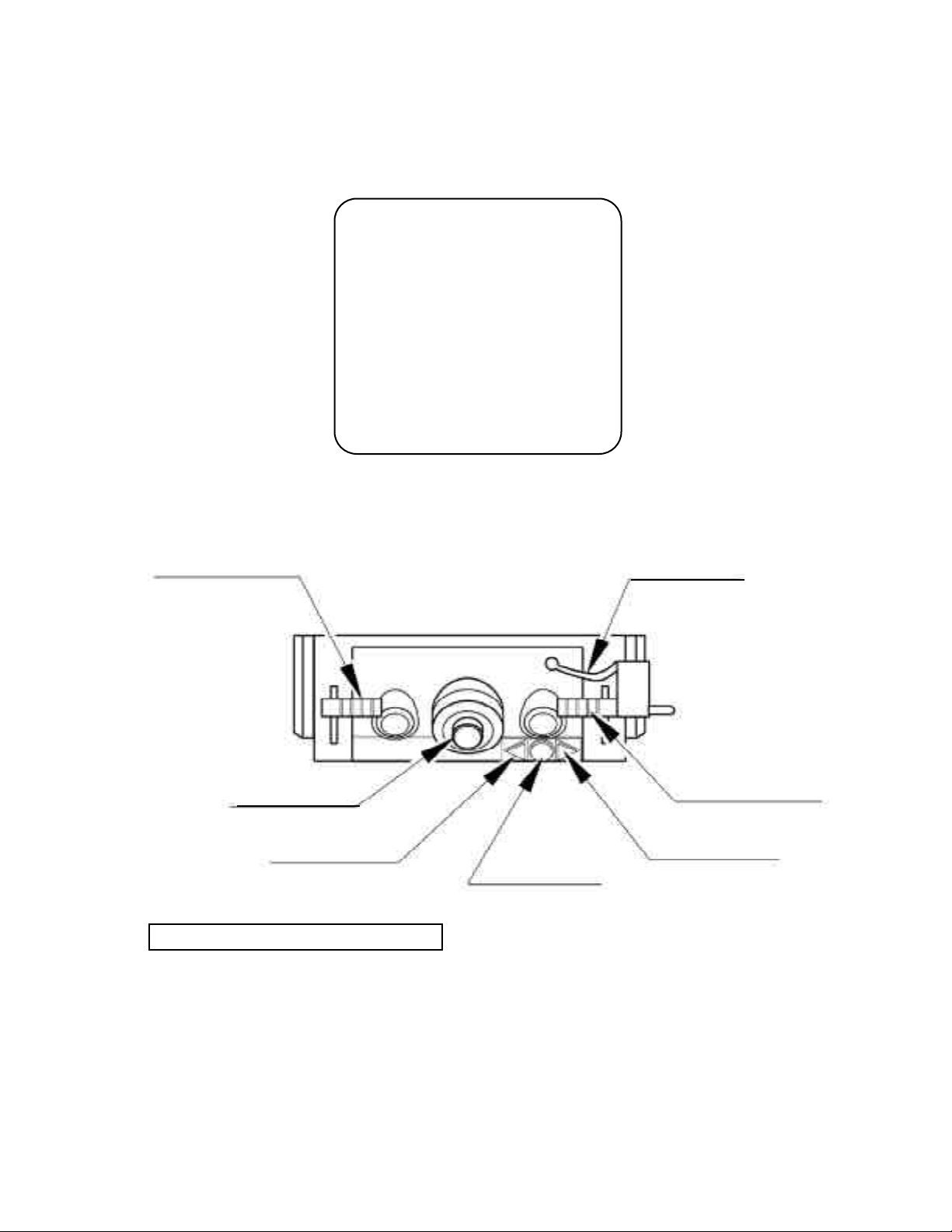
10 - 2 VOLUME ADJUSTMENT/REPLACEMENT
In case the operability of the right and left levers are poor, and the performed CALIBRATION in test mode does not improve the situation, the cause may be failure of the Volume
Gear’s engagement in the ASSY LEVER MECHA inside the control panel and or Volume
malfunctioning. Follow the following procedure to perform Volume adjustment or replacement. Since work is performed inside the energized cabinet, be very careful not to
touch undesigned places.
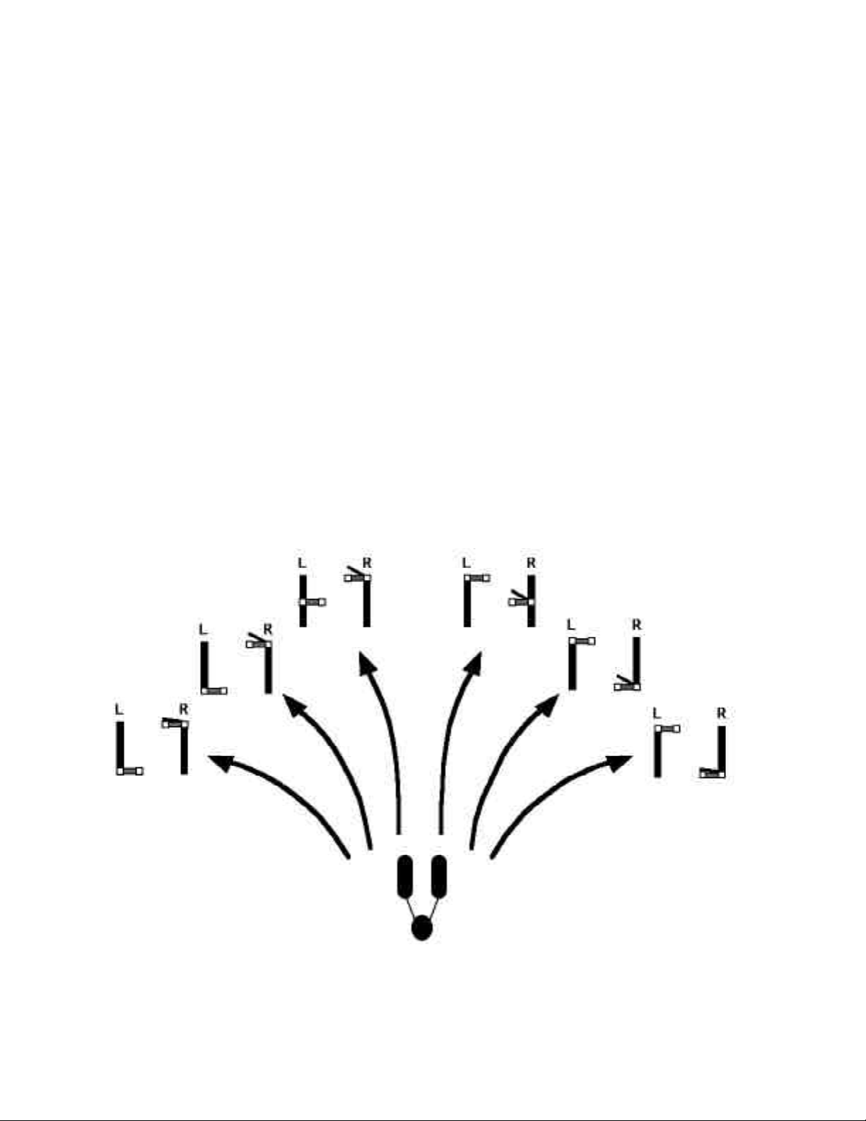
ADJUSTMENT
Turn power off and remove the CONTROL
1
PANEL COVER (10-1)
Loosen the 2 cscrews securing the VR
2
BRACKET in the ASSY LEVER MECHA
to push the gear out of mesh.
With the Lever being at the centering
3
position, bring the gear into mesh so that
the status of the volume’s shaft is as shown
in (FIG.10.2).
VR BRACKET
“D” CUT FACE
4
Fasten the screws securing the VR BRACKET.
5
Turn power on and perform volume setting in the CALIBRATION in the test mode. (9-3)
During the I/O TEST in the test mode, check to see if the volume value varies smoothly in
6
accordance with operation of the Lever. (9-3)
7
Turn off power.
8
Install the CONTROL PANEL COVER to change back to former state.
52
Page 55

REPLACEMENT
If the volume is in a status as per FIG. 10.2, moving the Lever fully forward and backward
does not damage parts, and the value does not exceed the Volume’s movable range.
Turn off power and remove the
1
CONTROL PANEL COVER (10-1).
Disconnect the connector from the
2
VOLUME to be replaced.
Take out the 2 screws securing the VR
3
BRACKET, in the ASSY LEVER
MECHA to remove the VR BRACKET
with the GEAR and VOLUME
mounted on it.
Disconnect the connector.
PHOTO 10.2 b
Remove the GEAR and
4
VOLUME from the VR
BRACKET and replace the
VOLUME
PHOTO 10.2 c
SCREW (2)
Flat & spring washers
5
With the Lever being at the centering position, bring the
gear into mesh so that the status of the volume’s shaft is as
shown in the Fig. (FIG.10.2)
6
Fasten the 2 screws securing the VR BRACKET.
7
Turn power on and perform the volume setting for CALIBRATION in the test mode.
During I/O TEST in test mode, check to see if the volume value varies smoothly in
8
PHOTO 10.2 d
accordance with operation of the Lever. (9-3)
9
Turn off power.
10
Install the CONTROL PANEL COVER to change back to the former state.
53
Page 56

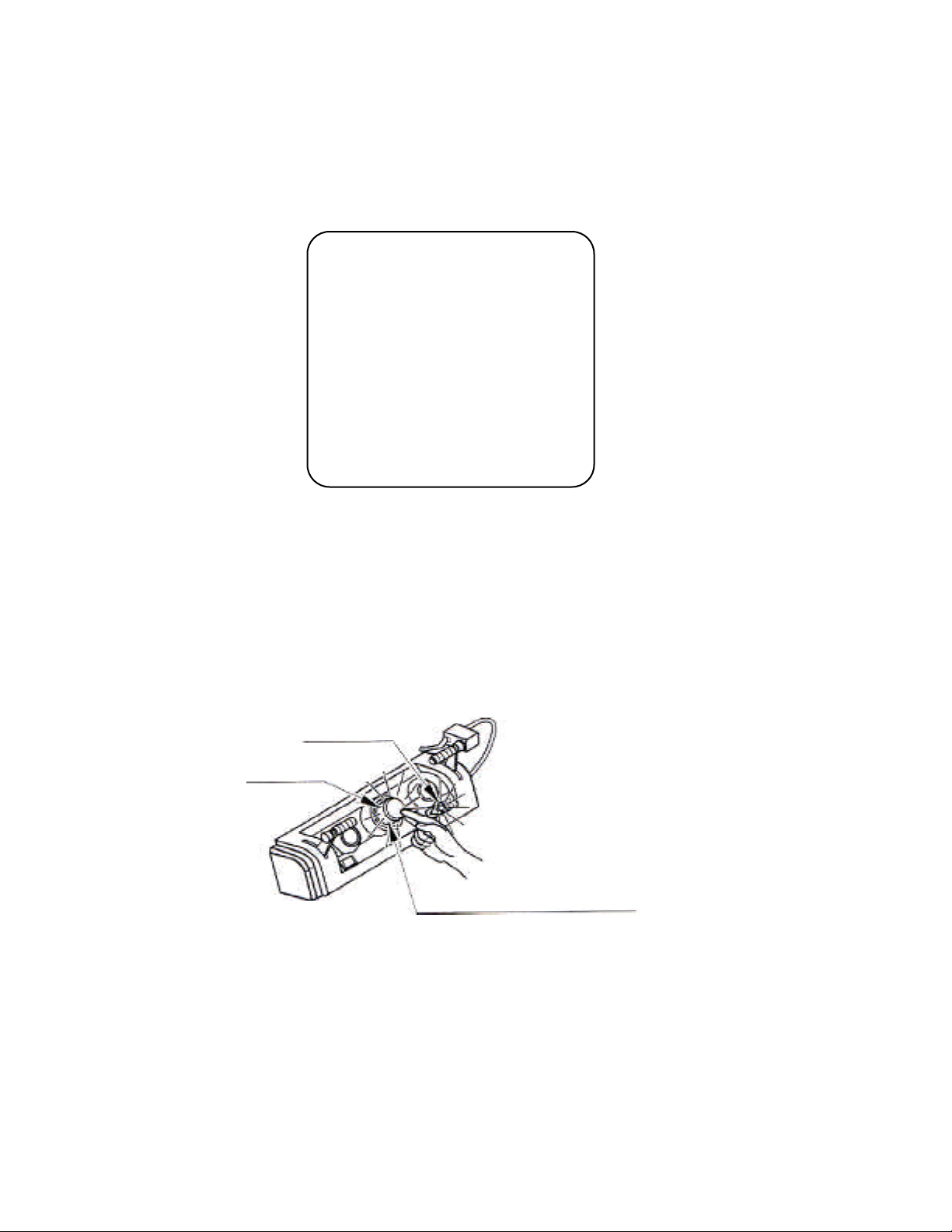
10 - 3 GREASING
Do not touch solenoid. The solenoid can be very hot.
Be sure to use the designated grease. Using undesignated grease can
cause parts damage.
Do not apply greasing to undesignated places. Failure to observe this
can cause malfunctioning or quality deterioration of parts.
The period for greasing specified herein is standard. Apply greasing
to specified portions as occasion arises.
Once every 3 months apply greasing to the volume mesh portion in the ASSY MECHA LEVER
and the ASSY BRAKE spring. For spray greasing, use GREASE MATE (PART NO.090-0066).
Apply greasing to the BOOST button MECHA portion semiannually. Use GREASE 248 (PART
NO.090-0070) for the portion. If the specified greasing is not obtainable, use greasing for the
cold-proof, heat resisting plastic instead.
APPLY GREASING TO THE ASSY MECHA LEVER
PHOTO 10.3 a VOLUME GEAR MESH PORTION
APPLY GREASING TO THE ASSY BRAKE
Insert the spray-greasing nozzle into the
square hole of the ASSY BRAKE
LEVER to apply greasing to the spring
portion.
54
Page 57

11 . COIN SELECTOR
HANDLING THE COIN JAM
If the coin is not rejected when the REJECT BUTTON is pressed, open the coin chute door
and open the selector gate. After removing the jammed coin, put a normal coin in and check
to see that the selector functions correctly.
CLEANING THE COIN SELECTOR
The coin selector should be cleaned
once every 3 months. When cleaning,
follow the procedure below:
1
Turn the power for the machine OFF.
Open the coin chute door.
2
Open the gate and dust off by using a
soft brush (made of wool, etc.).
3
Remove and clean smears by using a
soft cloth that has been dipped in water
or diluted chemical detergent and then
squeezed dry.
4
Remove the CRADLE.
When removing the retaining ring (Ering), be very careful so as not to bend
the shaft.
5
Remove stains from the shaft and
pillow portions by wiping with a soft
cloth, etc.
After cleaning, apply a dry cloth to dry
6
the coin selector completely.
GATE
FIG. 11a
CRADLE
FIG. 11b
Never apply machine oil, etc. to
the coin selector
After cleaning the Coin Selector,
insert a regular coin during the
normal working status to ensure
that the Selector functions correctly.
COIN INSERTION TEST
Once a month, when performing the COIN SW
TEST, simultaneously check the following:
Does the Coin Meter count satisfactorily?
Does the coin drop into the Cashbox correctly?
Is the coin rejected once inserted when the
REJECT BUTTON is kept pressed down?
Insert a coin
while keeping
the Reject
Button pressed
down and
check if it is
rejected.
COIN METER
FIG. 11c
55
Page 58

OPTIONAL DOLLAR BILL ACCEPTOR
THE COIN DOOR ASSEMBLY USED ON STAR WARS
POD RACER MINI DELUXE COMES EQUIPED TO ACCEPT
A DOLLAR BILL ACCEPTOR. ALL NEEDED WIRING
CONNECTIONS ARE CONVIENENTLY LOCATED INSIDE
THE GAME FOR THIS APPLICATION.
THE COIN DOOR CAN ACCOMMODATE THE FOLLOWING
VALIDATOR(S):
FORWARD-MOST Mars 2000 series
HOLE POSITION
**42-1155-00 MARS VALIDATOR $1,2,5 300 CAP
The frame and cashbox enclosure on this coindoor has been modified
to accommodate a Mars 2000 series stacker. It can be added by simply
removing the cut-out plate. This one entry door can be ordered through
Happ Controls authorized distributors. The part number is 40-6000-10EX.
The Mars stacker can be obtained through an authorized Mars distributor.
**Happ part number
56
Page 59

57
Page 60

**Coin door shown with optional dollar bill validator inserted**
58
Page 61

12. MONITOR
12 - 1 CAUTIONS AND WARNINGS CONCERNING THE SAFETY FOR HANDLING THE MONITORS
When performing such work as installing and removing the monitor, inserting and disconnecting the external connectors to and from monitor, be sure to disconnect the power connector
(plug) before starting work. Proceeding the work without following this instruction can cause
electric shock of malfunctioning.
Using the monitor by converting it without obtaining a prior permission is not allowed. SEGA
shall not be liable for any malfunctioning and accident caused by said conversion.
Primary side and secondary side
The monitor’s circuit which is divided into the Primary
side and secondary side, is electrically isolated. Do
not touch the primary side and the secondary side
simultaneously. Failing to observe the instruction can
cause electric shock, and this is very dangerous.
When making monitor adjustments, use a nonconductive driver and make adjustment without
touching any other part other than the Adjustment
V.R. and Knob. Also, be sure not to cause a shortcircuit to the Primary side and the Secondary side. If
short-circuited, it can cause electric shock or malfunctioning, which is very dangerous.
High tension Voltage
Some of the parts inside the monitor are subject to high-tension voltage in excess of 20,000
volts and very dangerous. Therefore, do not touch the monitor interior. Should soldering &
paper wastes, etc. be mixed in the monitor, turn the power off so as not to cause malfunctioning or fire hazard.
Connecting the CRT and PCB
For combining the CRT and PCB, use the specified part No. to maintain the status of adjustments made at the factory. The anode of the CRT itself will be accumulitavely charged as time
elapses, generating high tension voltage which is very dangerous. The monitor should be used
with the Chassis, CRT and PCB assembled. When repair, etc. is required at the time of malfunctioning, be sure to send it in an “as assembled” condition. If these are disassembled, what’s
charged to said high tension voltage can be discharged, causing a very hazardous situation.
Therefore, under no circumstances should it be disassembled.
Static Electricity
Touching the CRT surface sometimes causes you to slightly feel electricity. This is because the
CRT surfaces are subject to static and will not adversly affect the human body.
Installation and removal
Ensure that the Magnetizer Coil, FBT (Fly-Back Transformer), Anode Lead and Focus Lead are
not positioned close to the sheet metal work’s sharp edges, etc. and avoid damaging the
insulated portions so as not to cause an electric shock and malfunctioning. (For the name of
parts, refer to the above figures.)
59
Page 62

For the purpose of static prevention,
special coating is applied to the CRT
face of this product. To protect the
coating, pay attention to the following
points. Damaging the coating film can
cause electric shock to the customers.
For the caution to be heeded when
clearing, refer to the Section of Periodic
inspection Table.
Do not apply or rub with a hard item (a
rod with pointed edge, pen, etc.) to or
on C.R.T. surfaces.
Avoid applying stickers, seals, etc. on
the C.R.T. face.
Do not remove aluminum foils from the
C.R.T. corners. Removing the aluminum
foils can cause static prevention effects
to be lowered.
Monitor adjustments have been made at the time of shipment. Therefore do not make further adjustment without a justifiable reason.
Adjusting the monitor which contains high tension parts is dangerous
work. Also, an erroneous adjustment can cause deviated synchronization and image fault, resulting in malfunctioning.
When making adjustment, utilize a resinous Alignment Rod. Servicing
with bare hands or using conductive tools can cause electric shock.
12 - 2 CAUTIONS TO BE HEEDED WHEN CLEANING THE CRT SURFACES
Static preventive coating is applied to the CRT surfaces. Peeling off
this coating can cause electric shock. When cleaning, pay attention to
the following points:
Remove smears by using a dry, soft cloth (flannels, etc.). Do not
use a coarse gauze, etc.
For smear removing solvent, alcohol (ethanol) is recommended.
When using chemical detergent, e sure to folow instructions
below:
Dilute chemical detergent with water and dip a soft cloth in and
then thoroughly wring it to wipe smears off.
Do not use a chemical detergent containing an abrasive, powder
or bleaching agent.
Do not use alkaline chemical detergents such as “glass cleaner”
available on the market or solvents such as thinner, etc.
Do not rub or scratch the CRT face with hard items such as scrub
brushes, etc.
Clean the CRT surfaces once a week. When cleaning, pay attention to the above cautions so that the antistatic
coating will not come off.
60
Page 63

12 - 3 ADJUSTMENT METHOD
Monitor adjustments are made at the time of shipment. Therefore,
do not make further adjustments without a justifiable reason.
Adjusting a monitor which contains high tension parts is dangerous
work. Also, an erroneous adjustment can cause deviated synchronization and image fault, resulting in malfunction.
When making adjustments, utilize a resinous Alignment Rod. Servicing with bare hands or using tools made of conductive material
can cause electric shock.
61
Page 64

13. REPLACING THE FLUORESCENT LAMP AND BUTTONS
When performing the work, be sure to turn power off. Working
with power on can cause an electric shock or short circuit accident.
The fluorescent lamp, when it gets hot can cause burns. Be very
careful when replacing the Fluorescent Lamp.
To perform work safely and securely, be sure to use a step which is in a
secure and stable condition. Not using a step or using an unstable step can
cause violent falling accidents.
THE FLUORESCENT LAMP
Take out the 2 Truss Screws and remove the Plate Holder.
1
Lower the Billboard Plate and replace the Fluorescent Lamp.
2
LAMP COVER A
FLATHEAD SCREW (2)
M4 X 8 black
FLUORESCENT LAMP 20 W : LOCAL PURCHASE
START BUTTON AND VIEW CHANGE BUTTON
Be careful not to damage the wiring connection inside the start button and view change
button.
Turn power off.
1
Take out the 4 Truss Screws.
2
Disconnect the connector attached to the start button, and the VR
3
BUTTON START REVIEW 1can be removed.
62
Page 65

14. PERIODIC INSPECTION TABLE
The items listed below require periodic check and maintenance to retain the performance of
this machine and to ensure safe business operation. When handling the controller, the player
will be in direct contact with it. In order to always allow the player to enjoy the game, be
sure to clean it regularly. Also, it is advisable to provide wet tissue, etc. for player use.
Be sure to check once a year to see if power cords are damaged, the
plug is securely inserted, and dust is accumulated between the Socket
Outlet and the Power Plug, etc. Using the product with accumulated dust
can cause fire and electric shock hazzards.
Periodically once a year, request the place of contact herein stated or
the Distributor, etc. where the product was purchased from, as reguards
the internal cleaning. Using the product with accumulated dust in
the interior without cleaning can cause a fire or accident. Note that
cleaning the interior parts can be performed on a pay-basis.
TABLE 14
Item
CABINET
CONTROL PANEL
COIN CHUTE DOOR
PROJECTOR
SEAT
GAME BD
INTERIOR
POWER SUPPLY PLUG
Cabinet surfaces
Check Adjuster’s contact with surface.
Cleaning
Inspection of SW, VR.
Greasing to the gear mesh portion and the spring.
Greasing to the BOOST button.
Check COIN SW.
Coin insertion test.
Cleaning of COIN SELECTOR
SCREEN cleaning
Check adjustments
An anti-static electricity measure
Greasing to the seat rail
MEMORY TEST
Check settings
Cleaning
Inspection and cleaning
Cleaning
Interval
Daily
As necessary
Monthly
Trimonthly
Semiannually
Monthly
Monthly
Trimonthly
Weekly
Monthly or when
moving
Bimonthly
Trimonthly
Monthly
Monthly
Annually
As necessary
Reference
3
9
10-3
10-3
9
11
11
12-1
6, 9, 12
5
FIG.14
9
9
See above
See below
CLEANING THE CABINET SURFACES
When the cabinet surfaces are badly soiled, remove stains with a soft cloth dipped in water or diluted
(with water) chemical detergent and squeezed dry. To avoid damaging surface finish, do not use such
solvents as thinner, benzine,etc. other than ethyl alcohol, or abrasives, bleaching agent and chemical
dustcloth.
63
Page 66

15. DESIGN RELATED PARTS
2
1
5
3
4
ITEM NO. PART NO. DESCRIPTION
1 999-0983 MARQUEE
2 999-0982 POP PANEL
3 999-0984 RIGHT SIDE DECAL
NOT SHOWN 999-0985 LEFT SIDE DECAL
4 999-0986 RIGHT CENTER DECAL
NOT SHOWN 999-0987 LEFT CENTER DECAL
NOT SHOWN 999-1037 SEAT DECAL SET
5 999-1038 REAR POD (PLASTIC)
64
Page 67

16. PARTS LIST
SWITCH UNIT
ITEM NO. PART NO. DESCRIPTION
1 INY-1181 SW BRKT
2 421-8911 STICKER SW UNIT
10l 509-5028 SW PB lM
102 220-5179 VOL CONT B-5K OHM
103 601-0042 KNOB 22 MM
65
Page 68

ASSY AC UNIT (DRT1-0400)
ITEM NO. PART NO. DESCRIPTION
1 SPG5-0401 AC BRKT
101 600-5843-25 CA & PLUG ASSY 5A W/F-L=2.5M
102 280-5143-6N34 BUSHING STRAIN RELIEF 6N34
103 Local Purchase FUSE 5000 MA UL
105 509-5453-91-V-B SW ROCKER J8 V-B
66
Page 69
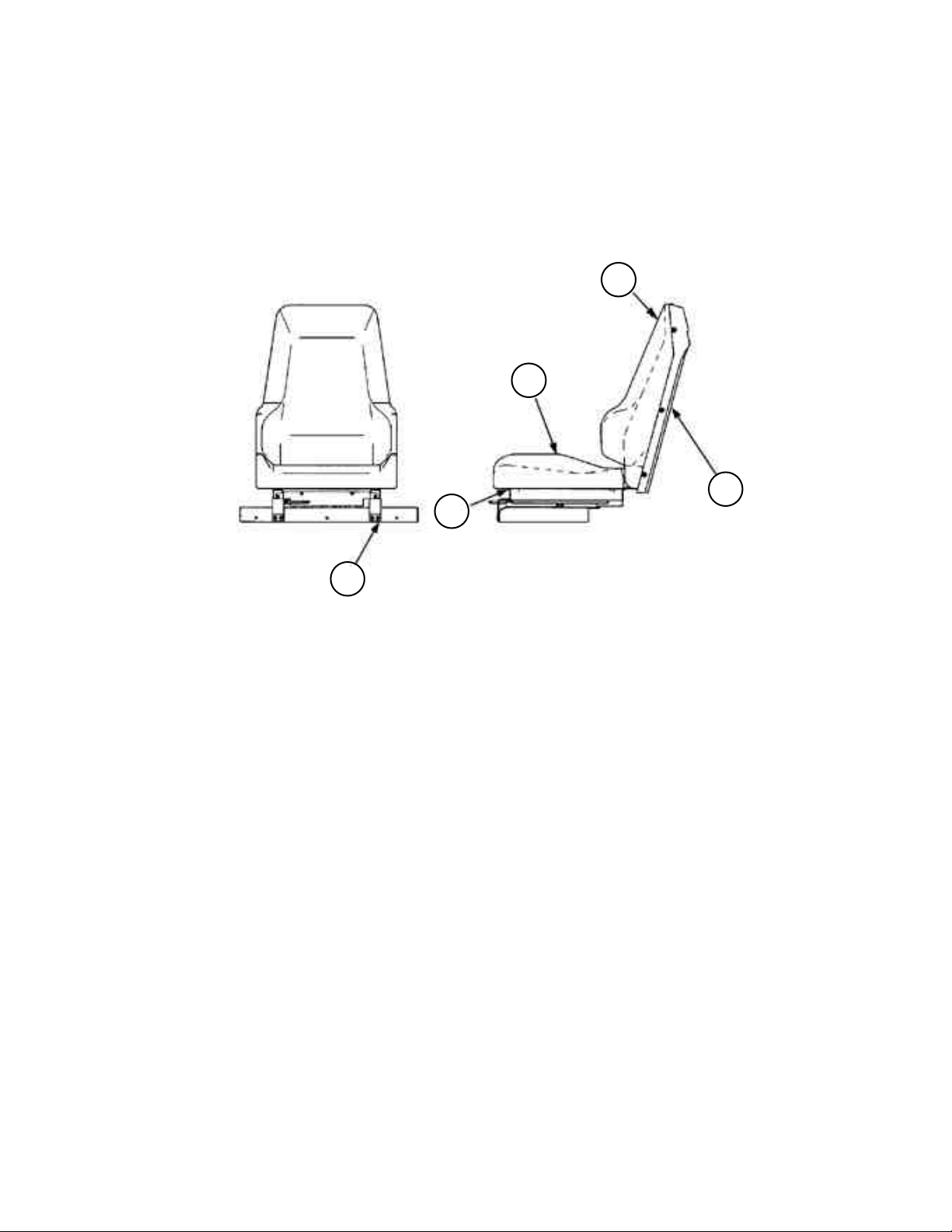
ASSY SEAT
1
2
5
3
4
ITEM NO. PART NO. DESCRIPTION
1 DNY0-2131 UPPER SEAT
2 DNY0-2132 LOWER SEAT
3 DYN1-2081 SEAT FRAME
4 DYN1-2084 SEAT BASE
5 999-1009 SEAT BACK (PURPLE)
67
Page 70

ASSY CONTROLLER (D-1/2)
68
Page 71

ASSY CONTROLLER (D-2/2)
ITEM NO. PART NO. DESCRIPTION
1 999-1010 ASSY LEVER MECHA
2 999-1011 BOOST BUTTON (IMPERIAL#54-0004-12)
3 999-1012 START SWITCH (IMPERIAL#57-2000-30)
4 999-1013 ASSY BRAKE
5 999-1014 CONTROLLER BASE
6 999-1015 CTRL PNL COVER
7 POD-2103 GRIP
8 POD-2104 GRIP END
9 999-1016 GRIP PIN
10 999-1017 SELECT SWITCH (IMPERIAL#57-2000-65)
69
Page 72
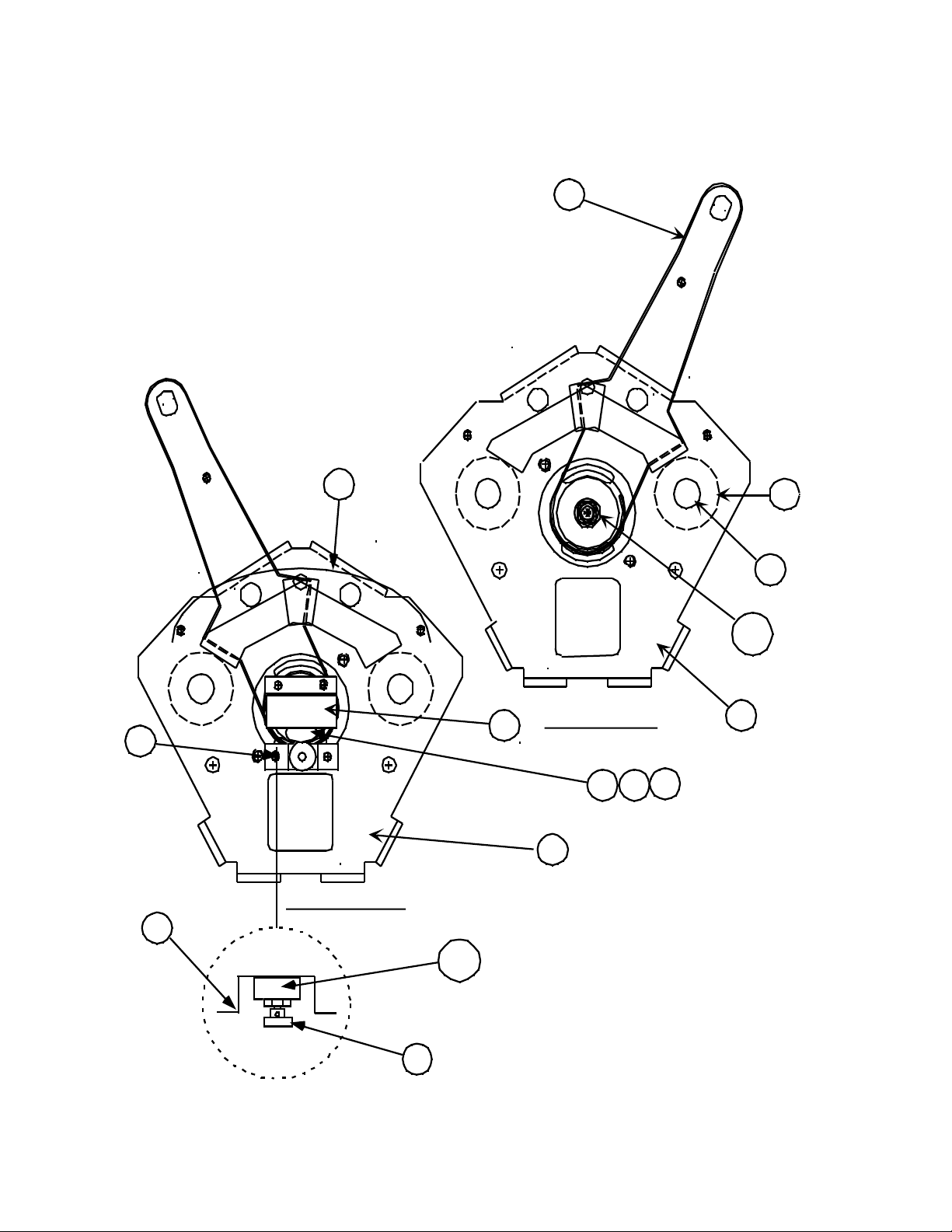
ASSY LEVER MECHA (999-1010)
3
1
Back View
13
102
12
Front View
4
5
6
11
10
8
9
2
7
Note : Your assembly may differ from this image.
It is for reference purposes only.
101
70
Page 73

ASSY LEVER MECHA (999-1010) (D-2/2)
ITEM NO. PART NO. DESCRIPTION
1 999-1018 LEVER BRKT INNER
2 999-0996 LEVER SHAFT
3 999-1019 STOPPER RUBBER LEVER
4 999-1000 GEAR HOLDER PLATE
5 999-1020 LEVER BRKT OUTER
6 999-1003 SHUTTER PLATE
7 999-1021 STOPPER SHAFT LEVER
8 999-0999 GEAR COVER
9 999-1005 GEAR HOLDER
10 999-1022 ADJUST GEAR
11 999-0998 VR BRACKET
12 999-1023 GEAR
13 999-1002 INSULATOR PAPER
101 999-1024 ROTARY DAMPER
102 999-1025 VOL CONTROL 5K LONG LIFE
71
Page 74

1
2
1. 999-1084 DISK INNER RORY DAMPR STW MINI
2. 999-1085 SPRING ROTARY DAMPR STW MINI
Page 75

ASSY BRAKE (999-1013)
ITEM NO. PART NO. DESCRIPTION
1 999-0994 BRAKE COVER UPPER
2 999-0995 BRAKE COVER LOWER
3 999-1026 BRAKE SHAFT
4 999-1027 TORSOIN SPRING BRAKE
5 999-1001 BRAKE LEVER
6 999-1028 MICRO SWITCH
7 999-1029 BRAKE COLLAR
8 999-1030 STOPPER SHAFT
9 999-1031 STOPPER RUBBER BRAKE
10 999-1032 GRIP PIN R
11 999-0997 MOUNTING BRACKET (not shown)
12 999-1033 HOSE END
13 999-1034 HOSE
14 999-1035 HARNESS (BRAKE)
15 999-1617 SPACER WASHER BRAKE ASSY
www.seuservice.com
72
Page 76

17. WIRE COLOR TABLE
THE WIRE COLOR CODE is as follow:
A PINK
B SKY BLUE
C BROWN
D PURPLE
E LIGHT GREEN
Wires other than those of any of the above 5 single colors will be displayed by 2
alphanumeric characters.
1 RED
2 BLUE
3 YELLOW
4 GREEN
5 WHITE
7 ORANGE
8 BLACK
9 GRAY
If the right-hand side number of the code is 0, then the wire will be of a single color shown
by the left-hand side number (see the above).
Note 1: If the number on the right-hand side is not 0, that particular wire has a spiral color
code. The left-hand side character shows thc base color and the right-hand side
one, lhe spiral color.
<Example> 51 ............... WHITE / RED
RED WHITE
Note 2: The character following the wire color code indicates the size of the wire.
U: AWG16
K: AWG18
L: AWG20
NONE: AWG22
73
Page 77

VISIT OUR WEBSITE!
Page 78

 Loading...