

Page 1

1st PRINTING MAY 00
SEGA ENTERPRISES, INC. USA
STD TYPE
OWNER’S MANUAL
MANUAL NO. 4200-6479-01
Page 2

Warranty
Your new Sega Product is covered for a period of 90 days from the date of shipment. This certifies
that the Printed Circuit Boards, Power Supplies and Monitor are to be free of defects in workmanship or materials under normal operating conditions. This also certifies that all Interactive Control
Assemblies are to be free from defects in workmanship and materials under normal operating conditions. No other product in this machine is hereby covered.
Sellers sole liability in the event a warranted part described above fails shall be, at its option, to
replace or repair the defective part during the warranty period. For Warranty claims, contact your
Sega Distributor.
Should the Seller determine, by inspection that the product was caused by Accident, Misuse, Neglect, Alteration, Improper Repair, Installation or Testing, the warranty offered will be null and void.
Under no circumstances is the Seller responsible for any loss of profits, loss of use, or other damages.
This shall be the exclusive written Warranty of the original purchaser expressed in lieu of all other
warranties expressed or implied. Under no circumstance shall it extend beyond the period of time
listed above.
Page 3

TABLE OF CONTENTS
INTRODUCTION OF THE OWNERS MANUAL
GENERAL PRECAUTIONS
1. PRECAUTIONS TO BE HEEDED FOR OPERATION
2. NAME OF PARTS
3. ACCESSORIES
4. ASSEMBLY AND INSTALLATION
5. PRECAUTIONS TO BE HEEDED WHEN MOVING MACHINE
6. CONTENTS OF GAME
7. EXPLANATION OF TEST AND DATA DISPLAY
7-1 SWITCH UNIT AND COIN METER
7-2 SYSTEM TEST MODE
A C.R.T. TEST
B COIN ASSIGNMENTS
7-3 GAME TEST MODE
A INPUT TEST
B OUTPUT TEST
C SOUND TEST
D C.R.T. TEST
E GAME ASSIGNMENTS
F
VOLUME SETTING
G BOOKKEEPING
H BACKUP DATA CLEAR
8. CONTROL MECHA
8-1 REMOVING THE CONTROL MECHANISM
8-2 ADJUSTING THE VOLUME
8-3 REPLACING THE VOLUME
8-4 GREASING
8-5 REPLACING THE SWITCH LEVER
9. LEVER UNIT
9-1 ADJUSTING THE VOLUME
9-2 REPLACING THE VOLUME
9-3 GREASING
10. PEDAL UNIT
10-1 ADJUSTING THE VOLUME
10-2 REPLACING THE VOLUME
10-3 GREASING
11. COIN SELECTOR
12. MONITOR
12-1 CAUTIONS/WARNINGS FOR HANDLING
12-2 CAUTIONS TO BE HEEDED WHEN CLEANING
12-3 ADJUSTMENT METHOD
13. REPLACING THE FLUORESCENT LAMP
14. PERIODIC INSPECTION TABLE
15. TROUBLESHOOTING
16. GAME BOARD
16-1 LOCATING THE GAME BOARD
16-3 COMPOSITION OF THE GAME BOARD
18. DESIGN RELATED PARTS
19. PARTS LIST
20. WIRING DIAGRAMS
1
2~3
4~5
6
7~8
9~16
17
18~20
21~34
22
23~29
24
25~29
30~34
31
31
32
32
33
33
34
34
35~38
35
36
36
37
38
39~40
39
40
40
41~42
41
42
42
43~45
46~48
46~47
47
48
49
50
51
52~53
52
53
54~55
56~92
XXX
Page 4

SPECIFICATIONS
Installation space: 37.2 in.(W) x 64.0 in.(D)
Height: 73.6 in.
Weight: Approx. 617.3 lbs.
Power maximum current: 2.3 Amp AC 120V 60 Hz
MONITOR: 29” COLOR MONITOR
INTRODUCTION OF THE OWNERS MANUAL
SEGA ENTERPRISES, LTD., has for more than 30 years been supplying various innovative and
popular amusement products to the world market. This Owners Manual is intended to provide
detailed descriptions together with all the necessary installation, game settings and parts ordering
information related to AIRLINE PILOTS STD TYPE, a new SEGA product.
This manual is intended for those who have knowledge of electricity and technical expertise, especially in ICs, CRTs, microprocessors, and circuit boards. Read this manual carefully to acquire
sufficient knowledge before working on the machine. Should there be a malfunction, non-technical
personnel should under no circumstances touch the interior system. Should the need arise, contact
our main office, or the closest branch office listed below.
SEGA ENTERPRISES, INC. (USA)
Customer Service
45133 Industrial Drive
Fremont, CA 94538
Phone 415-701-6580
Fax 415-701-6594
7:30 am - 4:00 pm, Pacific Standard Time
Monday thru Friday
Page 5

General Precautions
Follow Instructions: All operating and use instructions should be followed.
Attachments: Do not use attachments not recommended by the product manufacturer as they may cause hazards.
Accessories: Do not place this product on an unstable cart, stand, tripod, bracket, or table. The product may fall,
causing serious injury to a child or adult, and serious damage to the product. Use only with a cart, stand, tripod, bracket, or
table recommended by the manufacturer, or sold with the product. Any mounting of the product should follow the
manufacturer’s instructions, and should use only mounting accessories recommended by the manufacturer.
Moving the Product: This product should be moved with care. Quick stops, excessive force, and uneven surfaces
may cause the product to overturn.
Ventilation: Slots and openings in the cabinet are provided for ventilation, to ensure reliable operation of the product
and to protect it from overheating; these openings must not be blocked or covered. The openings should never be blocked
by placing the product in a built-in installation such as a bookcase or rack unless proper ventilation is provided or the
manufacturer’s instructions have been adhered to.
Power Sources: This product should be operated only from the type of power source indicated on the marking label.
If you are not sure of the type of power supply to your location, consult your local power company. For products intended
to operate from battery power or other sources, refer to the operating instructions.
Grounding or Polarization: This product is equipped with a three-wire grounding-type plug, a plug having a third
(grounding) pin. This plug will only fit into a grounding-type power outlet. This is a safety feature. If you are unable to
insert the plug into the outlet, contact your electrician to replace your obsolete outlet. Do not defeat the safety purpose of the
grounding-type plug.
Power Cord Protection: Power-supply cords should be routed so that they are not likely to be walked on or pinched
by items placed upon or against them, paying particular attention to cords at plugs, convenience receptacles, and the point
where they exit from the product.
Overloading: Do not overload wall outlets, extension cords, or integral convenience receptacles as this can result in
a risk of fire or electric shock.
Object and Liquid Entry: Never push objects of any kind into this product through openings as they may touch
dangerous voltage points or short-out parts that could result in a fire or electric shock. Never spill liquid of any kind on the
product.
Servicing: Do not attempt to service this product yourself as opening or removing covers may expose you to danger-
ous voltage or other hazards. Refer all servicing to qualified service personnel.
Damage Requiring Service: Unplug this product from the wall outlet and refer servicing to qualified service person-
nel under the following conditions:
a) If the power cord or plug is damaged;
b) If liquid has been spilled, or objects have fallen into the product;
c) If the product has been exposed to rain or water;
d) If the product does not operate normally when following the operating instructions. Adjust only those controls that
are explained in the operating instructions. An improper adjustment of other controls may result in damage and will
often require extensive work by a qualified technician to restore the product to its normal operation;
e) If the product has been dropped or damaged in any way;
f) When the product exhibits a distinct change in performance; this indicates a need for service.
Replacement Parts: When replacement parts are required, be sure the service technician has used replacements parts
specified by the manufacturer or that have the same characteristics as the original part. Unauthorized substitutions may
result in fire, electric shock, or other hazards.
Page 6

Safety Check: Upon completion of any service or repairs to this product, ask the service technician to perform safety
checks to determine that the product is in proper operating condition.
Heat: The product should be situated away from heat sources such as radiators, heat registers, stoves, or other prod-
ucts (including amplifiers) that produce heat.
Lithium Battery- Dispose of batteries only in accordance with the battery manufacturer’s recommendations.
Do not dispose in an open flame condition, since the battery may explode.
Cleaning: When cleaning the monitor glass, use water or glass cleaner and a soft cloth. Do not apply chemicals such
as benzine, thinner, etc.
Location: This an indoor game machine, DO NOT install it outside. To ensure proper usage, avoid installing indoors
in the places mentioned below:
• Places subject to rain/water leakage, or condensation due to humidity;
• In close proximity to a potential wet area;
• Locations receiving direct sunlight;
• Places close to heating units or hot air;
•In the vicinity of highly inflammable/volatile chemicals or hazardous matter;
• On sloped surfaces;
• In the vicinity of emergency response facilities such as fire exits and fire extinguishers;
• Places subject to any type of violent impact;
• Dusty places.
INSTALLATION PRECAUTIONS
• Verify the amperage of the branch circuit outlet before plugging in the power plug. Do not overload the circuit.
• Avoid using an extension cord. If one is required, use an extension cord of type SJT, 16/3 AWG
rated min. 120 VAC, 7A.
• Moving this unit requires a minimum clearance (of doors, etc.) of 32” (W) by 77” (H).
• For the operation of this machine, secure a minimum area of 32” (W) by 42”(D).
REGULATORY APPROVALS
This game has been tested and found to comply with the Federal Communications Commission Rules.
This device complies with Part 15 of the FCC Rules. Operation is subject to the following two conditions: (1) This
device may not cause harmful interference, and (2) this device must accept any interference received, including interference
that may cause undesired operation.
This game has been tested and listed by Underwriters Laboratories, Inc., to ANSI/UL22.
Page 7
1 . PRECAUTIONS TO BE HEEDED FOR OPERATION
In order to prevent accidents, be sure to comply with the following points before and during operation.
PRECAUTIONS TO BE HEEDED FOR OPERATION BEFORE STARTING THE OPERATION
In order to avoid accidents, check the following before starting the operation:
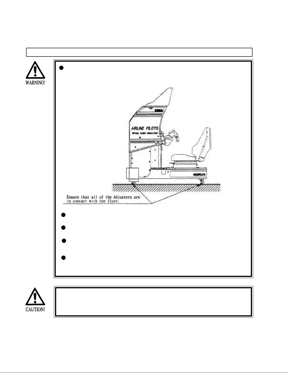
Check if all of the adjusters are in contact with the surface. If they are not,
the cabinet can move and cause an accident.
Do not climb on the product. Climbing on the product can cause falling
down accidents. To check the top portion of the product, use a step.
To avoid electric shock, check to see if door & cover parts are closed.
To avoid electric shock, short circuit and or parts damage, do not put the
following items on or in the periphery of the product:
Flower vases, flower pots, cups, water tanks, cosmetics, and receptacles/
containers/vessels containing chemicals and water.
To avoid injury, be sure to provide sufficient space by considering the
potentially crowded situation at the installation location. Insufficient installation space can cause the player to come into contact with or hit others
and result in injury or trouble.
Page 8
PRECAUTIONS TO BE HEEDED DURING OPERATION
To avoid injury and accidents, those who fall under the following catagories are not
allowed to play the game:
* Intoxicated persons
* Those who have high blood pressure or heart problems.
* Those who have experienced muscle convulsion or loss of consciousness when
playing video games, etc.
* Persons susceptible to motion sickness.
* Persons whose acts runs counter to the products warning displays.
* Instruct those who wear high-heeled shoes to refrain from
playing the game by explaining that playing the game with highheeled shoes is very dangerous and likely to cause a potentially
hazardous situation.
To avoid electric shock and short circuit, do not allow customers to put hands and
fingers or extraneous matter in openings of the product or small openings in or around
doors.
To avoid electric shock and short circuit, do not allow the customers to unplug the
power plug without a justifiable reason.
Although this product has the accident preventive covering attached to potentially
hazardous places where hand and fingers could be caught, small children are unable to
perceive hazards. Use care so that small children do not come close to the product when
in play.
Immediately stop such violent acts as hitting and kicking the product. Such violent acts
can cause parts damage and/or falling down, resulting in injury due to fragments and
falling down.
Page 9
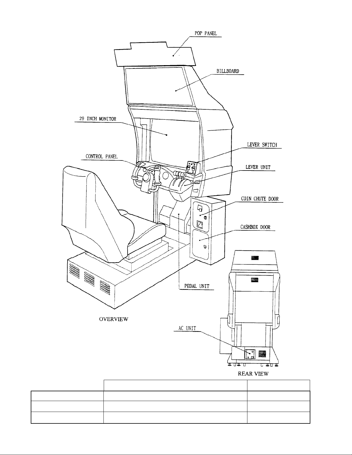
2 . NAME OF PARTS
GAME SPECIFICATIONS
DURING SHIPPING
WHEN ASSEMBLED
WIDTH in. LENGTH in. HEIGHT in.
All measurements are and rounded UP
42” X 60” X 65”
37.25” X 64” X 73.75”
WEIGHT lbs.
669 LBS.
619 LBS.
Page 10
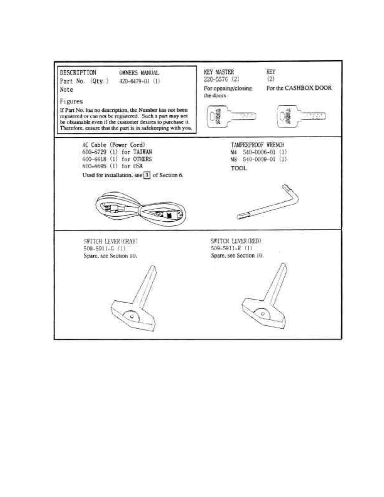
3 . ACCESSORIES
Page 11
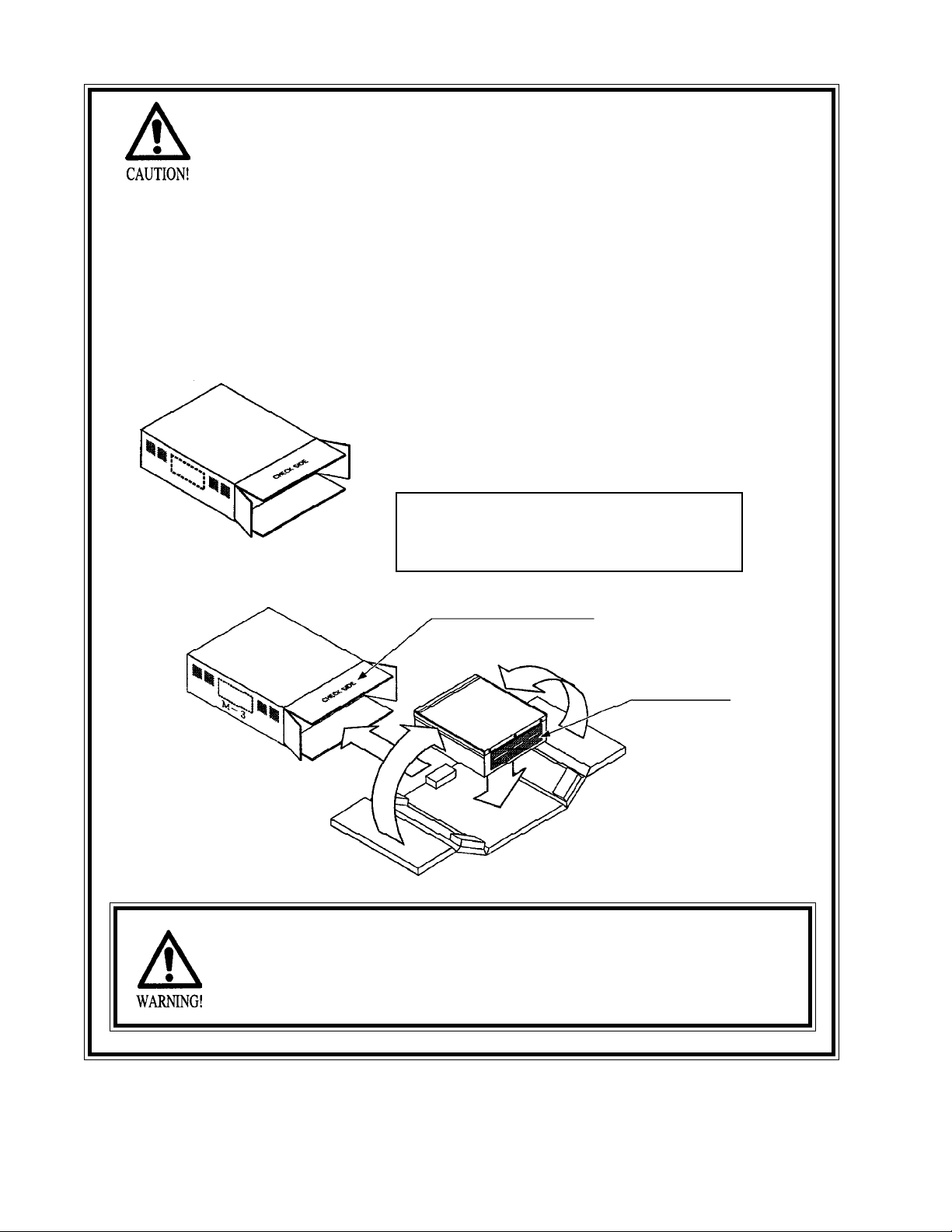
THE SHIPMENT METHOD DESCRIBED BELOW ONLY
APPLIES TO ‘MODEL 3’ BOARDS CONTAINED IN THE
FOLLOWING GAMES:
LOST WORLD, VIRTUA FIGHTER 3, SUPER GT, SEGA BASS FISHING, STRIKER 2
HARLEY DAVIDSON, RALLY 2, DAYTONA 2, DIRT DEVILS, HOUSE OF THE DEAD
2, OCEAN HUNTER, STAR WARS TRILOGY, ZOMBIE REVENGE, CRAZY TAXI,
ARILINE PILOTS
!!!!NNEEVVEERR SSHHIIPP MMOODDEELL 33 // NNAAOOMMII GGAAMME
BBOOAARRDDSS OOUUTTSSIIDDEE OOFF CCAAGGEE!!!
CARTON BOX
601-8928 (1)
Used for transporting the GAME BOARD.
{SUPPLIED WITH YOUR GAME}
DO NOT SHIP GAME BOARD WITHOUT
THIS BOX AS IT MAY DAMAGE THE GAME
BOARD AND VOID YOUR WARRANTY.
“CHECK SIDE” Display
FILTER BOARD
!
E
NO OTHER GAMES BOARDS ARE TO BE SHIPPED IN THE CAGE AS
THEY MAY BE DAMAGED BEYOND REPAIR. PLEASE SHIP THEM
WITHOUT CAGE PROPERLY PROTECTED DURING SHIPPING.
Page 12
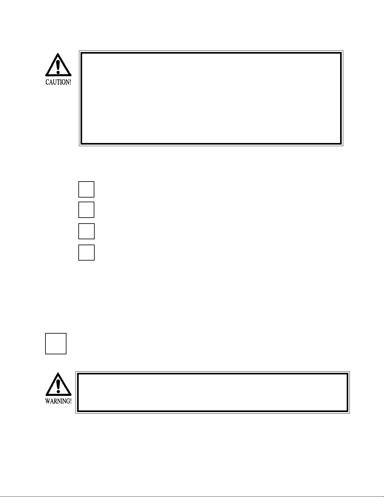
4 . ASSEMBLING AND INSTALLATION
-Assembling should be performed as per this manual. Since this is a
complex machine, erroneous assembling may cause damage to the
machine, or malfunctioning to occur.
-When assembling, be sure to perform work by plural persons.
Depending on the assembly work, there are some cases in which
performing the work by a single person can cause personal injury or
parts damage.
-Be careful so as not to damage wirings. Damaged wiring can cause
electric shock and short circuit hazards.
When carrying out the assembly work, follow the procedure in the following 5-item sequence:
ASSY OF BILLBOARD
1
2
SECURING IN PLACE (ADJUSTER ADJUSTMENT)
3
POWER SUPPLY
ASSEMBLING CHECK
4
Note that the tools such as a phillips screwdriver and wrench for M16 hexagon bolt w/24 mm width
across flats are required for the assembly work.
ASSY OF BILLBOARD
1
Due to its large size, it is very difficult for one person alone to install the billboard,
Make sure 2 or more persons are available to perform this work. Attempting to
perform the installation alone can cause an accident.
Page 13
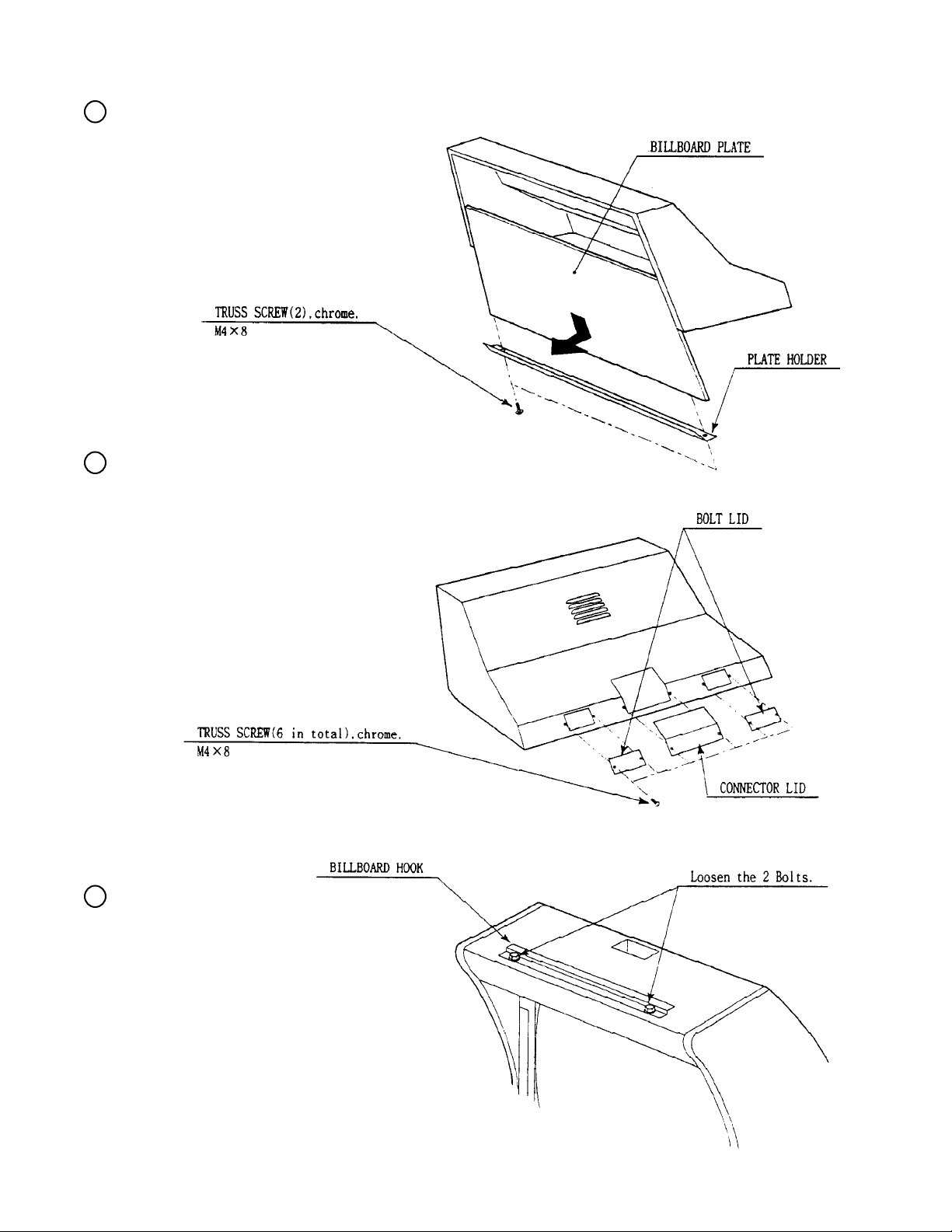
Take out the 2 screws, and
1
remove the Plate Holder &
Billboard Plate.
2
From the rear of the Billboard,
remove the 2 Bolt Lids and
the Connector Lid by taking
out 2 screws from each
3
Loosen the 2 Bolts securing
the Billboard Hook.
Page 14
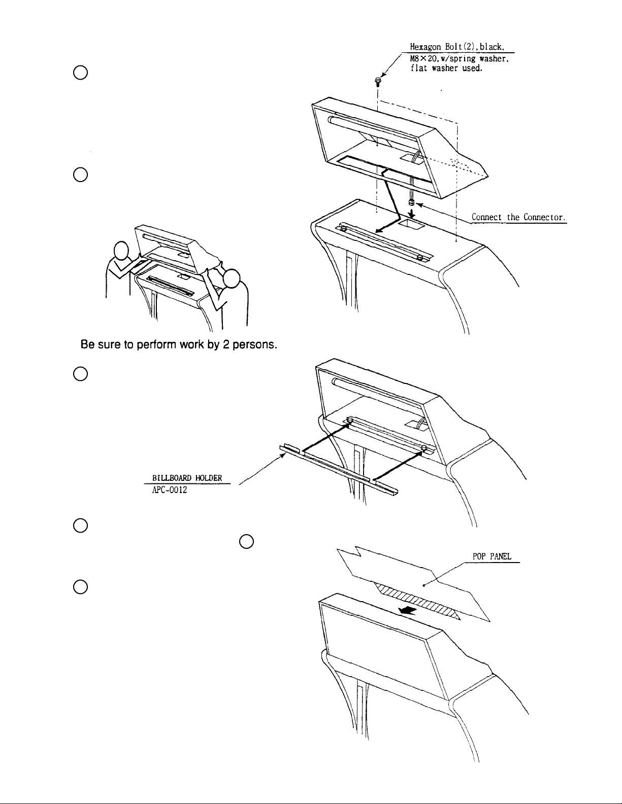
Mount the Billboard by hanging
4
on the Billboard Hook, secure
the Billboard with 2 Bolts
through the square holes of Bolt
Lids previously removed, and
connect the Connector.
Install the 2 Bolt Lids and
5
Connector Lid.
Insert the Billboard Holder in
6
place so as to fit the bolt
positions, and fasten the bolts
to secure the Billboard.
7
Install the Billboard Plate by
using the procedure opposite
above
Apply the oblique line portion
8
of the POP PANEL to the upper
rear part of the Billboard. At this
time, ensure that the POP does
not disappear.
1
Page 15
2
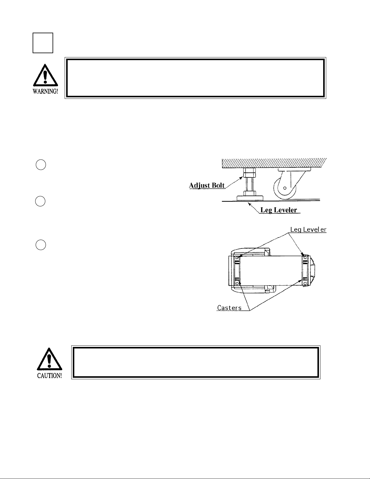
SECURING IN PLACE (ADJUSTER ADJUSTMENT)
Be sure to have all the Adjusters make contact with the floor surface.
Unless the Adjusters come into contact with the floor surface, the
Cabinet can move of itself, causing an accident.
This machine has 4 each of casters and adjusters (shown below). When the installation position is determined, cause
the adjusters to come into contact with the floor directly, make adjustments in a manner so that the casters will be
raised approximately 5mm. from the floor and make sure that the machine position is level.
1
Move the machine to the installation position,
making sure to provide adequate space for the
player to get on and off.
2
Cause all of the leg levelers to make contact
with the floor. By using a wrench, make
adjustments in the height of the leg adjusters to
ensure that the machine's position is kept level.
After making adjustments, fasten the leg
3
adjuster nut upward and secure the height of the
leg adjuster.
Permanantly tightening the hex bolts should not be completed until
the leg levelers are adjusted properly.
Page 16
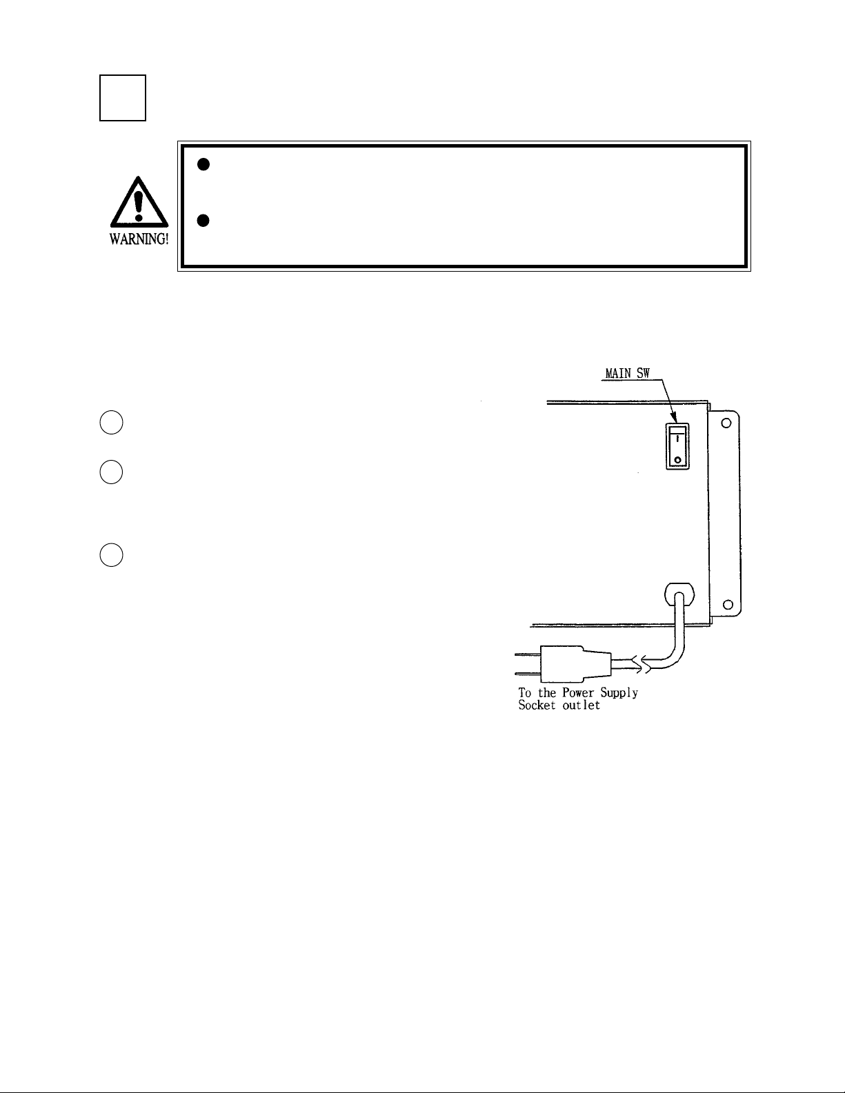
3
Connect the game to the power supply and turn on power to the game. Before connecting power supply be sure that
power switch is off
1
2
POWER SUPPLY
Ensure that the power cord is not exposed on the surface (passage,
etc.). If exposed, they can be caught and are susceptible to damage.
If damaged, the cord can cause an electric shock or short circuit.
Ensure that the wiring position is not in the customer's passage way
or the wiring has protective covering.
Turning the AC unit’s main switch on will cause the machine
to start the power check and network check automatically.
In the Power On check, the steering wheel turns left and right,
and then returns to the centering position and stops. In this
check, the values of the VR inside the control panel are
corrected.
Until this check is finished, and the steering wheel stops, do
3
not touch the steering wheel or play the game.
If you do, the steering reaction during the game (reaction at
the time of course-out or crash) can not be obtained correctly.
In the case of an abnormal reaction during the game, turn
power on again from the beginning and complete the power on
check.
Page 17

4
The TEST MENU allows for each part of the cabinet to be checked, the Monitor to be adjusted, and the coin and game
related various functions to be performed.
In the TEST MODE, ascertain that the assembly has been made correctly and that the IC BOARD is satisfactory.
In the test mode, perform the following test:
ASSEMBLING CHECK
(1) MEMORY TEST
RAM TEST
IC29 GOOD
IC35 GOOD
IC16 GOOD IC18 GOOD
IC20 GOOD IC22 GOOD
IC09 GOOD IC10 GOOD
IC11 GOOD IC12 GOOD
PRESS TEST BUTTON TO EXIT
ROM BOARD TEST
[AIRLINE PILOTS IN XXXX]
NO. TYPE RESULT BYTE WORD
IC22 32M ---- XXXX XXXX
IC1 64M GOOD XXXX XXXX
IC2 64M GOOD XXXX XXXX
IC3 64M GOOD XXXX XXXX
IC4 64M GOOD XXXX XXXX
IC5 64M GOOD XXXX XXXX
IC6 64M GOOD XXXX XXXX
IC7 64M GOOD XXXX XXXX
IC8 64M GOOD XXXX XXXX
IC9 64M GOOD XXXX XXXX
IC10 64M GOOD XXXX XXXX
IC11 64M GOOD XXXX XXXX
Selecting the RAM TEST and ROM TEST on
the test mode menu screen causes the onboard memory to be tested automatically.
The game board is satisfactory if the display
beside each IC No. shows GOOD.
PRESS TEST BUTTON TO EXIT
Page 18
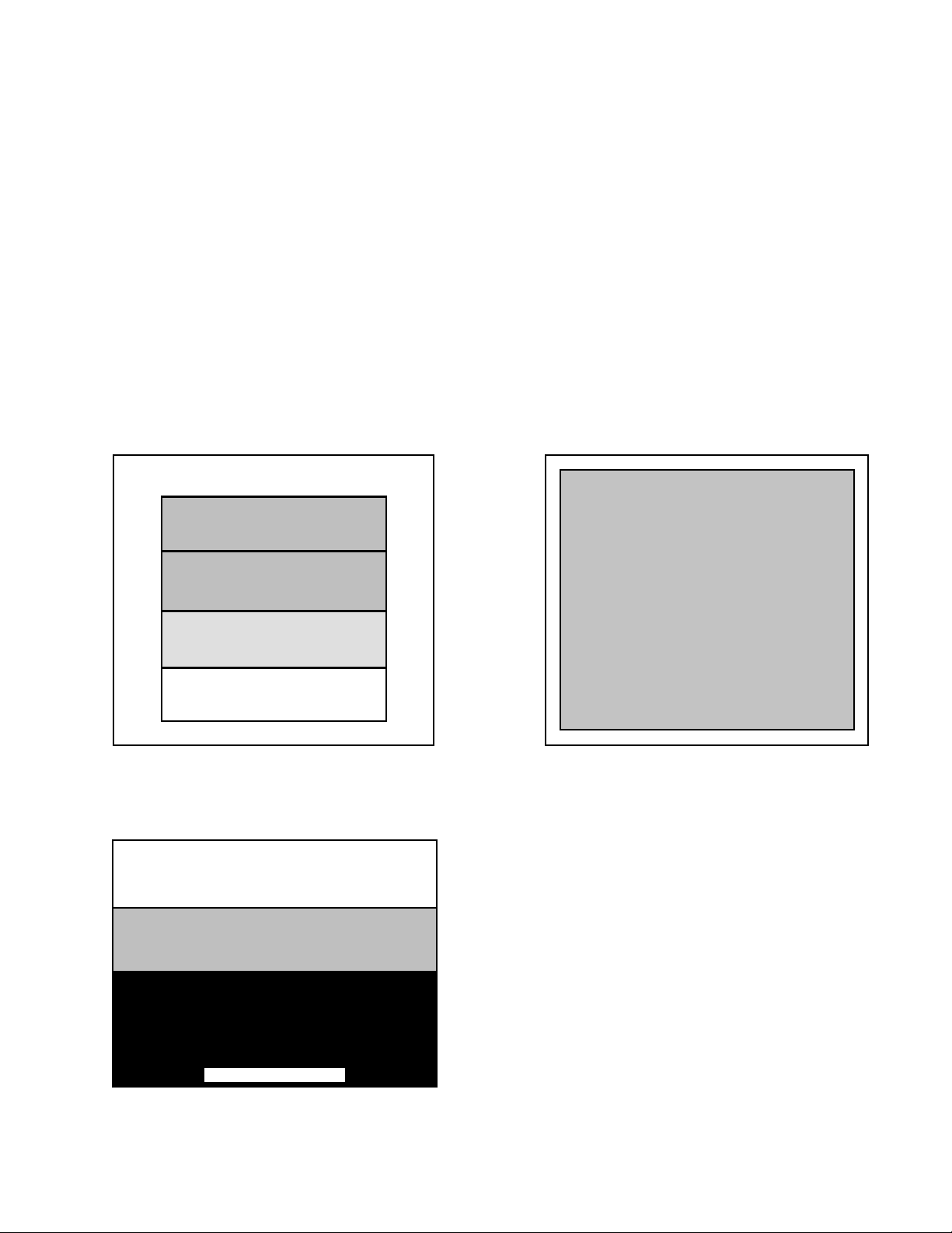
(2) C.R.T. TEST
In the TEST mode menu, selecting C.R.T. TEST allows the screen (on which the monitor is tested) to be
displayed. Although the monitor adjustments have been made at the time of shipment from the factory, color
deviation, etc., may occur due to the effects of geomagnetism, the location of the building’s steel frames and
other game machines in the periphery. By watching the test mode screen, make judgement as to whether an
adjustment is needed. If it is neccessary, adjust the projector by refering to Section 7.
In the C.R.T. test of SYSTEM TEST mode, adjust color and screen size.
In the C.R.T. test of GAME TEST mode, adjust monitor brightness.
SYSTEM TEST mode
C.R.T. TEST 1/2
1 32
GREEN
WHITE
PRESS TEST BUTTON TO CONTINUE
GAME TEST mode
C.R.T. TEST
C.R.T. TEST 2/2
RED
BLUE
PRESS TEST BUTTON TO EXIT
PRESS TEST BUTTON TO EXIT
Page 19

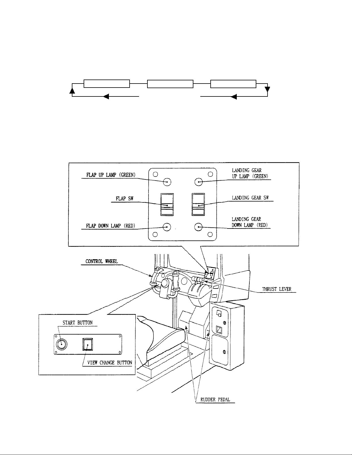
(3) INPUT TEST
INPUT TEST
LANDING GEAR SWITCH UP
FLAP SWITCH UP
VIEW CHANGE BUTTON OFF
START BUTTON OFF
SERVICE OFF
TEST OFF
CONTROL WHEEL (AILERON) ABH
CONTROL WHEEL (ELEVATOR) ABH
RUDDER PEDAL ABH
THRUST LEVER L ABH
THRUST LEVER R ABH
PRESS TEST AND SERVICE BUTTON TO EXIT
(4) OUTPUT TEST
OUTPUT TEST
START BUTTON LAMP OFF
LANDING GEAR UP LAMP OFF
LANDING GEAR DOWN LAMP OFF
FLAP UP LAMP OFF
FLAP DOWN LAMP OFF
VIEW CHANGE BUTTON LAMP OFF
Selecting the INPUT TEST on the game test mode
menu screen carses the screen (on which each switch
and V.R. are tested) to be displayed. Press each switch.
If the display beside each switch indicates “ON,” the
switch and wiring connections are satisfactory.
Select OUTPUT TEST from the menu in the game test
mode to cause the screen (on which each lamp is tested)
to appear. Ensure that each lamp lights up satisfactorily.
->EXIT
SELECT WITH SERVICE BUTTON AND PRESS
(5) SOUND TEST
SELECT WITH SERVICE BUTTON AND PRESS
TEST BUTTON TO EXIT
Perform the above inspections also at the time of monthly inspection.
TEST BUTTON
SOUND TEST
No. 0
In the TEST mode, selecting SOUND TEST causes the
screen, on which sound related BD and wiring connections are tested, to be displayed. Be sure to check if the
sound is satisfactorily emitted from each speaker and
that the sound volume is appropriate.
Page 20
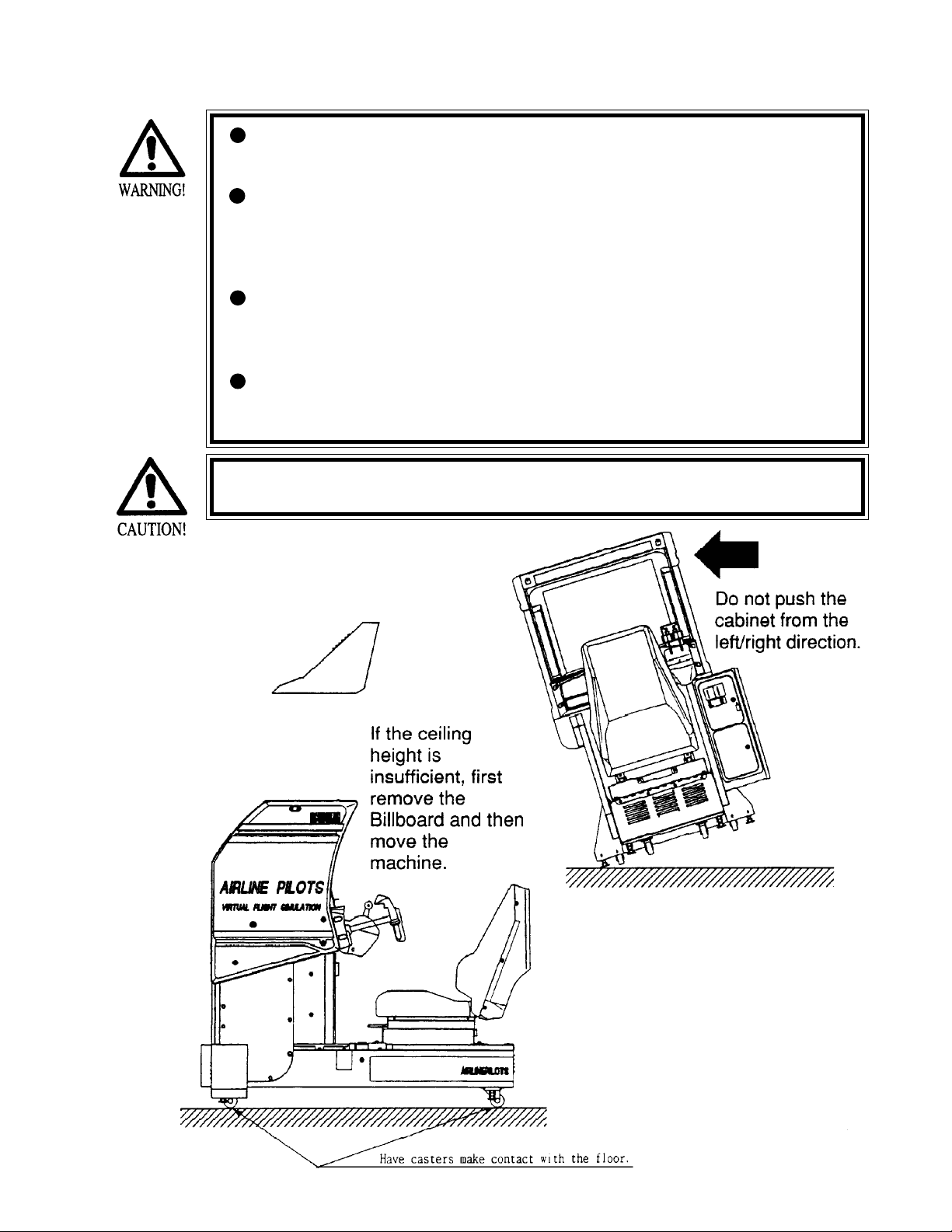
5 . PRECATIONS TO BE HEEDED WHEN MOVING THE MACHINE
When moving the machine, be sure to pull out the plug from the
power supply. Moving the machine with the plug inserted can damage
the power cord and cause a fire or electric shock.
When moving the machine on the floor, retract the Adjusters and
ensure that Casters make contact with the floor. During transportation, pay careful attention so that Casters do not tread power cords.
Damaging the power cords can cause an electric shock and/or short
circuit.
When lifting the cabinet, be sure to hold the catch portions or bottom
part. Lifting the cabinet by holding other portions can damage parts
and installation portions, due to the empty weight of the cabinet, and
cause personal injury.
When lifting the machine, do not push the cabinet from the left/right
direction. Doing so can cause the cabinet to fall down, resulting in
personal injury and or parts damage.
Use care when handling glass made parts. When the glass is damaged,
fragments of glass can cause injury
Page 21
6 . CONTENTS OF GAME
The following explanations apply in the event the product is functioning satisfactorily. Should there be any moves
different from the following contents, some sort of faults may have occured. Immediately look into the cause of the
fault and eliminate the cause thereof to ensure satisfactory operation.
SEGA LOGO
Returns to the beginning
TITLE GAME MODE
♦From GAME START up to the end of SELECT.
Insert a credit worth a number of coins. Up to 9 credits can be counted at a time. Coins inserted after counting 9 credits
are neither counted as credits nor returned. However, those coins inserted after counting 9 credits are included in the data
display or coin meter as number of coins inserted
Page 22
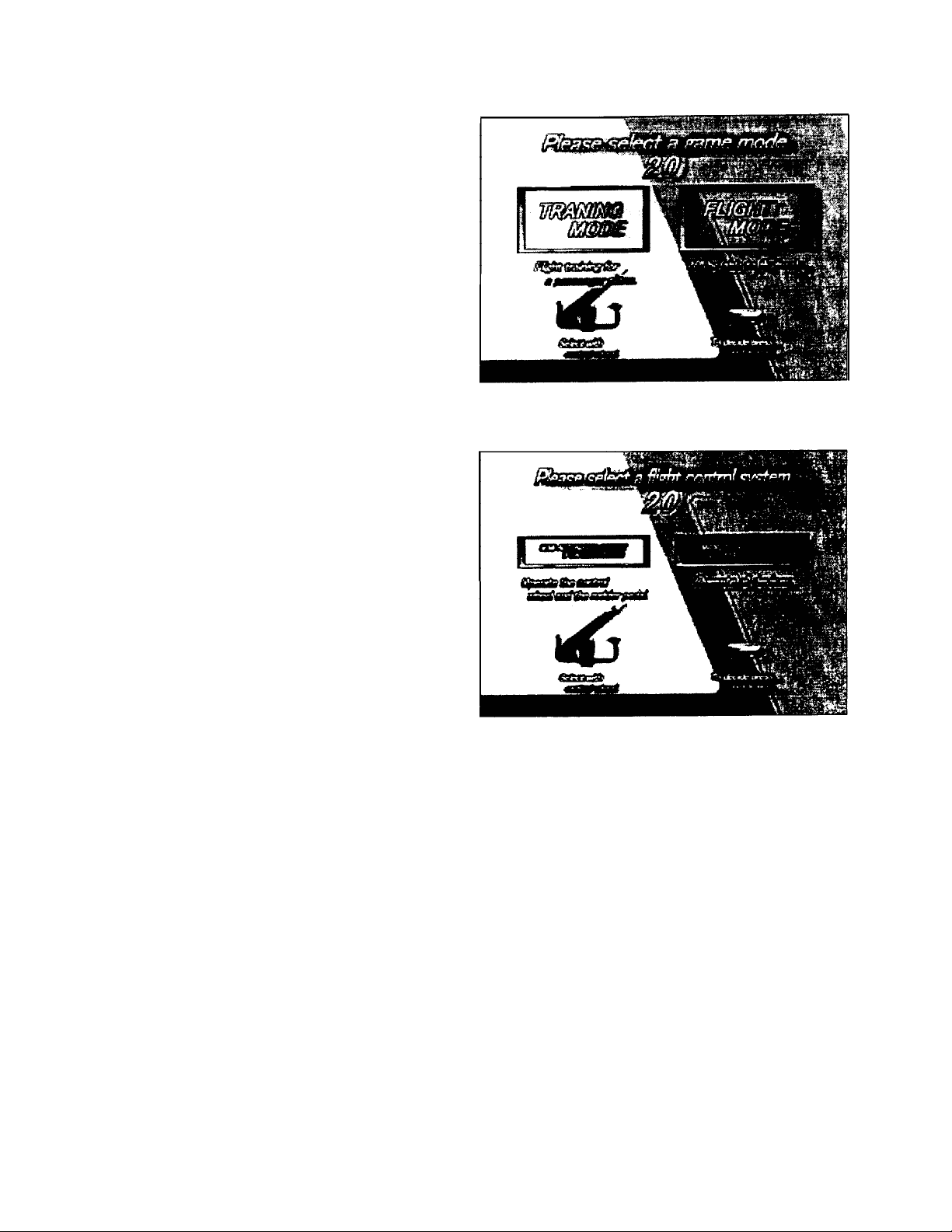
Press the START button to start.
When the GAME MODE select screen
appears, select TRAINING mode or
FLIGHT mode.
-Incline the CONTROL WHEEL left
or right to select and press the START
button to confirm the selection
(hereafter, this method applies to any
selection).
<In the case TRAINING MODE is selected:>
•When the CONTROL SYSTEM select
screen appears, select AUTO CONTROL
or FULL CONTROL.
•In the AUTO CONTROL, only the
CONTROL WHEEL and the RUDDER
PEDAL are operated by the player. The
FLAP SW, LANDING GEAR SW, and
THRUST LEVER are automatically
controlled.
•In the AUTO CONTROL, Control
Switches need not be set. The TRAINING
MODE game starts immediately.
•In the FULL CONTROL, the TRAINING mode game starts after setting Control Switches in accordance
with the on-screen instruction.
•In the FULL CONTROL, all Contollers are operated by the player.
Page 23
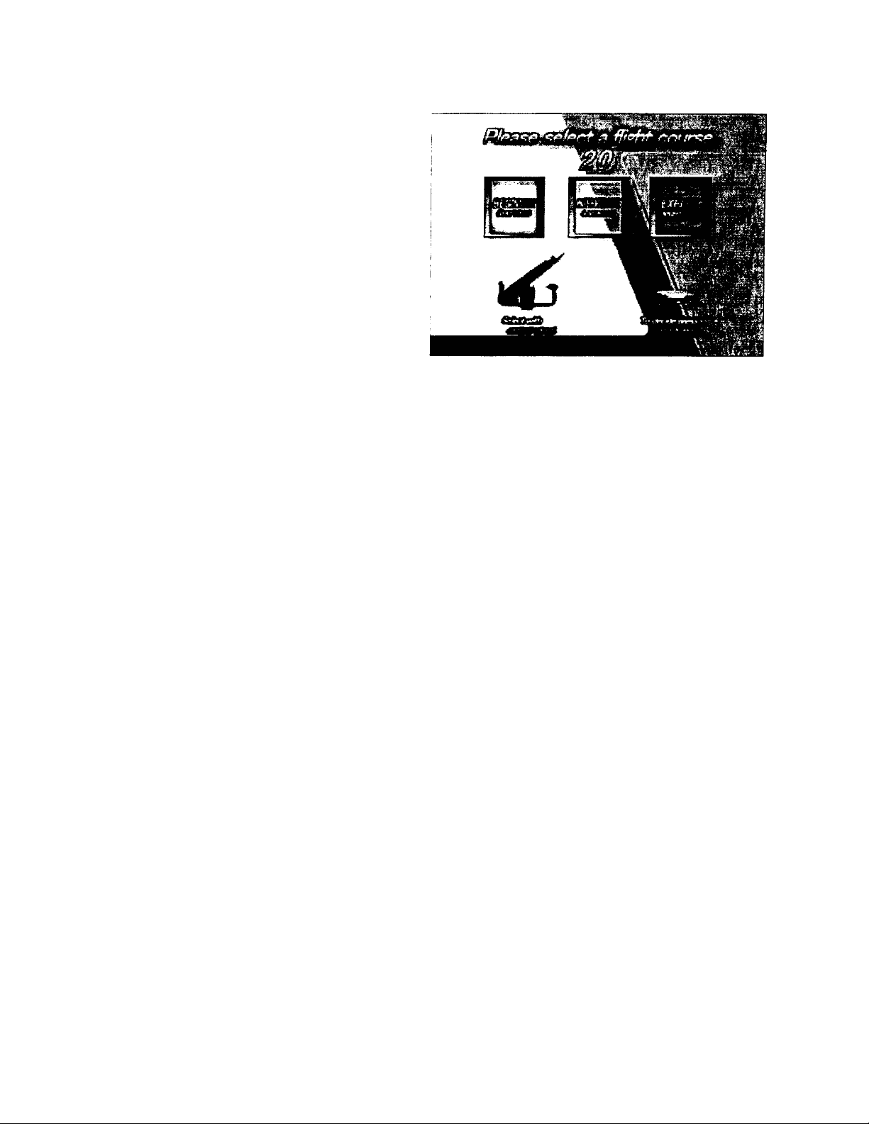
<In the case FLIGHT MODE is selected:>
-The FLIGHT COURSE select mode appears
on the screen. Select one from among
BEGINNER, INTERMEDIATE, and
EXPERT.
-The specific flight course of BEGINNER,
INTERMEDIATE, and EXPERT corresponds to flight in the daytime, evening, and
nighttime respectively.
-When the CONTROL SYSTEM select screen
appears, select the CONTROL SYSTEM in the
similar manner as in the TRAINING MODE
♦HOW TO PLAY IN THE TRAINING MODE
•This mode has 5 Training items, i.e., taking-off, turning, landing, evading engine trouble, and bad weather.
•The qualifying score is predetermined for each training item. If the player is disqualified, CONTINUE? appears on
the screen.
•CONTINUE? appears on the screen also when nearing the end of flight time limit, deviating from the course and
crashing.
•When CONTINUEd, the game starts from the beginning of that particular training.
•When all of the training items are cleared, the total score will be displayed and the game is finished.
♦HOW TO PLAY IN FLIGHT MODE
•Take off from the airport and freely fly over Tokyo within the time limit.
•Passing near the Time Marker floating in the air increases the time limit.
•When nearing the time limit, select FLIGHT to continue flight for the remaining time or landing.
•Select FLIGHT to continue up to the end of the time limit. When time is up, CONTINUE? appears on the screen. If
CONTINUEd, flight can be continued again. When the LANDING MODE is selected, the on-screen scene changes
to the LANDING course. If the landing is successful, the game is finished. Failing to make a landing results in a
Page 24
7 . EXPLANATION OF TEST AND DATA DISPLAY
By operating the switch unit, periodically perform the tests and data check. When installing the machine initially or
collecting cash, or when the machine does not function correctly, perform checking in accordance with the explanations
given in this section. The following shows tests and modes that should be utilized as applicable.
CAUTIONS TO BE HEEDED WHEN USING THE TEST MODE:
In the case where plural machines are linked for communication play, if even one seat enters
the test mode, all of the linked seats will enter the test mode. Therefore, if any one of the
linked machines is in play, use care so as not to use the test mode.
The contents of the setting changes made will not be effective unless the test mode is
finished in the test mode. When the setting is changed, be sure to “EXIT” in the menu mode.
Do not press the TEST BUTTON during network check at the time of turning the power on or
exiting from the test mode. If anyone of the linked machines uses the test mode during
network check, all other Seats will continue network checking. Cause all of the Seats to
reenter the test mode and then have all of the Seats exit from the test mode simultaneously.
TABLE EXPLANATION OF TEST MODE
ITEMS DESCRIPTION SECTIONS
When the machine is installed, perform the following:
INSTALLATION
OF MACHINE
1. Check to see that each setting is as per the standard settings at the
time of shipment.
2. In the INPUT TEST mode, check each SW and VR.
3. In the OUTPUT TEST mode, check each of lamps.
4. In the MEMORY TEST mode, check ICs on the IC Board.
SERVICE MANUAL
7 - 3A
7 - 3B
4- 4-1
MEMORY
PERIODIC
SERVICING
CONTROL
SYSTEM
MONITOR
IC BOARD
DATA CHECK
Choose MEMORY TEST in the MENU mode to allow the
MEMORY test to be performed. In this test, PROGRAM
RAMs, ROMs, and ICs on the IC Board are checked.
Periodically perform the following:
1. MEMORY TEST
2. Ascertain each setting.
3. In the INPUT TEST mode, test the CONTROL device
4. In the OUTPUT TEST mode, check each of lamps.
1. In the INPUT TEST mode, check each SW and VR.
2. Adjust or replace each SW and VR.
3. If the problem can not be solved yet, check the CONTROL’s moves.
In the MONITOR ADJUSTMENT mode, check to see if the
MONITOR adjustment is appropriately made.
1. MEMORY TEST
2. In the SOUND TEST mode, check the sound related ROMs.
Check such data as game play time and histogram to adjust the
difficulty level, etc
SERVICE MANUAL
4- 4-1
4- 4-1
7 - 3A
7 - 3B
7 - 3A
8, 9 , 1 0
1 2-3
4 - 4- 1
7 - 3 C
7 -3E
7 - 3 G
Page 25
7 - 1 SWITCH UNIT AND COIN METER
Never touch places other than those specified. Touching places not
specified can cause electric shock and short circuit.
Adjust to the optimum sound volume by considering the environmental
requirements of the installation location.
If the COIN METER and the game board are electrically disconnected,
game play is not possible.
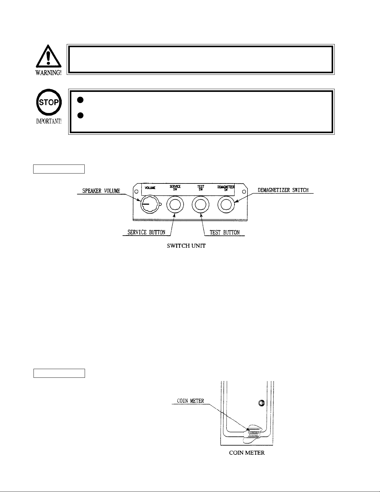
Open COIN CHUTE DOOR, and the switch unit shown appears. The function of
each switch is as follows:
SWITCH UNIT
SPEAKER VOLUME (VOLUME)
Controls the speaker volume for the right/left speakers.
SERVICE BUTTON (SERVICE SW)
Gives credits without registering on the coin meter.
TEST BUTTON (TEST SW)
For the handling of the TEST BUTTON, refer to the section on test mode.
DEMAGNETIZER SWITCH (DEMAGNETIZER SW)
Eliminates the on-screen color unevenness due to magnetization of CRT.
First use this SW before performing the monitor’s color adjustment.
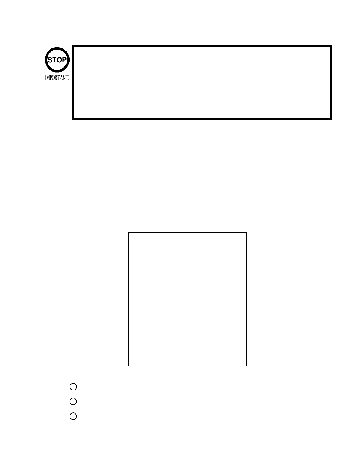
COIN METER
Open the Cashbox Door by using the key to
have the Coin Meter appear underneath the
Cashbox.
Page 26
7 - 2 SYSTEM TEST MODE
•The contents of settings changed in the TEST mode are stored when the TEST
mode is finished from EXIT in the MENU mode. If the power is turned off before the
TEST mode is finished, the contents of the setting changes do not take effect.
•Executing “BACKUP DATA CLEAR” in the SYSTEM TEST MODE does not clear the
BOOKKEEPING data in the GAME TEST MODE.
•Entering the TEST mode clears fractional numbers of coins less than one credit and
BONUS ADDER data.
The SYSTEM TEST mode mainly allows checks of the IC Board for accurate functioning , monitor adjustment, as well
as CRT TEST and COIN ASSIGNMENTS, etc. The following assignments, however, should be designated for this
product.
♦ CABINET TYPE : 1 PLAYER (S)
♦ MONITOR TYPE : HORIZONTAL
♦ COIN CHUTE TYPE : COMMON
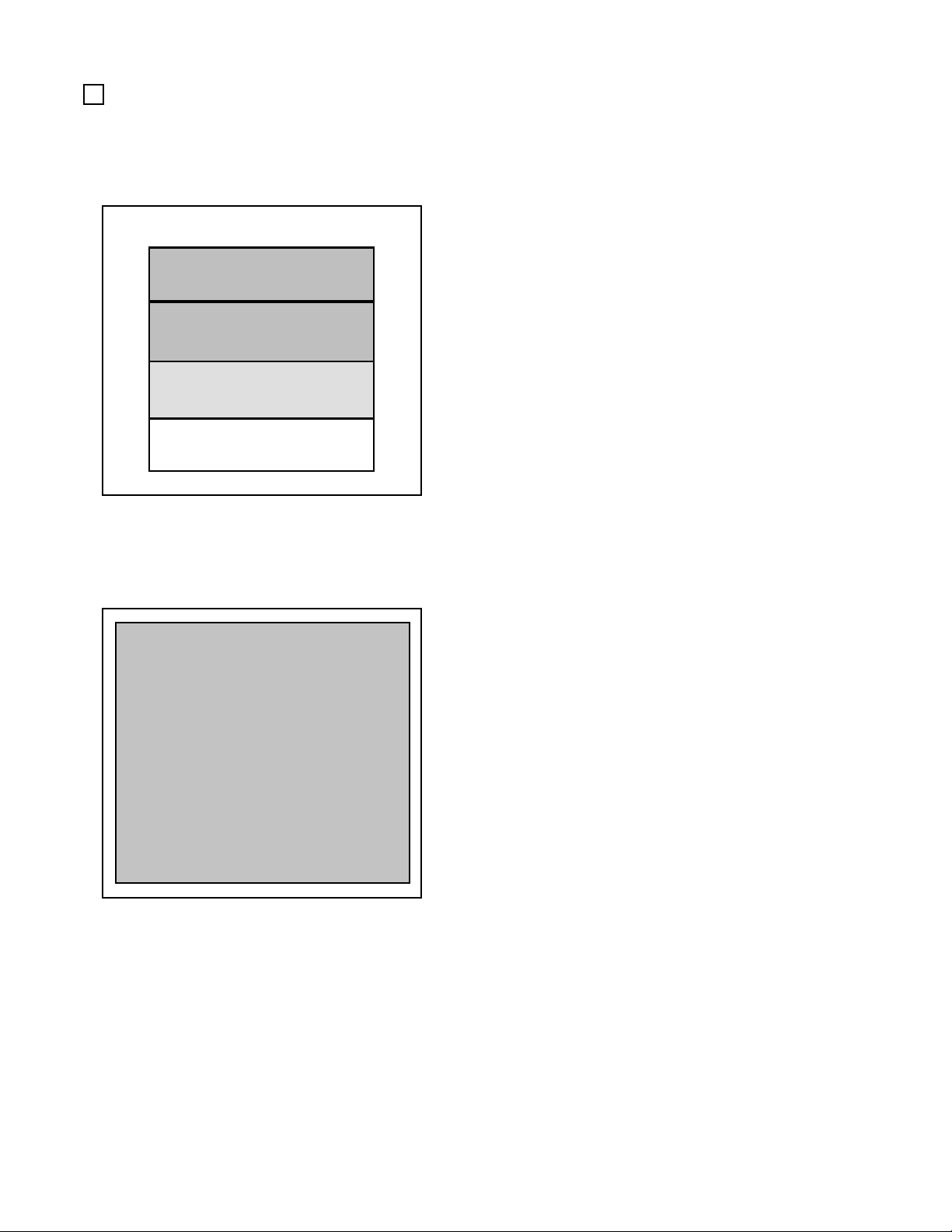
TEST ITEM SELECT
SYSTEM MENU
RAM TEST
JVS TEST
SOUND TEST
C.R.T. TEST
SYSTEM ASSIGNMENTS
COIN ASSIGNMENTS
BOOKKEEPING
BACKUP DATA CLEAR
CLOCK SETTING
ROM BOARD TEST
GAME TEST MODE
[ X X X X X X X X X X X ]
EXIT
SELECT WITH SERVICE BUTTON
AND PRESS TEST BUTTON
1
After turning the power on, press the TEST button to display the test item menu shown above.
2
Press the SERVICE button to move the arrow to the desired item and press the TEST button.
3
When finished, bring the arrow to EXIT and press the TEST button to return to the Game mode.
Page 27
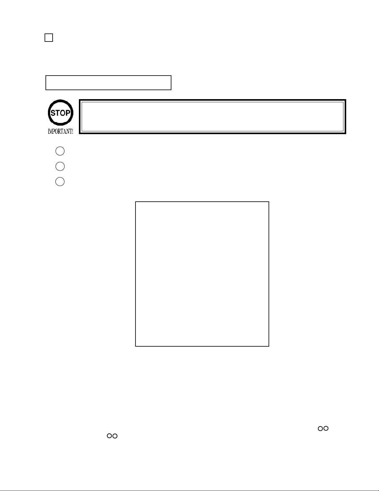
A C.R.T. TEST
1) RGB COLOR ADJUSTMENT SCREEN
In this screen, monitor color can be checked.
C.R.T. TEST 1/2
1 32
RED
GREEN
BLUE
WHITE
PRESS TEST BUTTON TO CONTINUE
2) MONITOR SIZE ADJUSTMENT SCREEN
In this screen, monitor size can be checked.
C.R.T. TEST 2/2
Each of red, green, and blue is the darkest at the
leftmost end, and becomes brighter towards the
right-hand end in 31 gradiations. Monitor brightness
is satisfactory if the white color bar is black at the
left end and if it is white at the right end.
Press the TEST button to proceed to the next screen.
Adjust the crosshatch frame line so that the checkered pattern does not extend beyond the screen.
Press the TEST button to return to the menu mode.
PRESS TEST BUTTON TO EXIT
Page 28
B COIN ASSIGNMENTS
The “COIN ASSIGNMENTS” mode permits you to set the start number of credits, as well as the basic numbers
of coins and credits. This mode expresses “how many coins correspond to how many credits.”
SETTING CHANGE PROCEDURE
Setting changes cannot be stored unless the TEST BUTTON is pressed
while the arrow is on EXIT.
Press the SERVICE BUTTON to move the arrow to the desired item.
1
Change the desired item setting by using the TEST BUTTON.
2
To return to the MENU mode, move the arrow to EXIT and press the TEST BUTTON.
3
COIN ASSIGNMENTS
COIN CHUTE TYPE COMMON
COIN/CREDIT SETTING #1
COIN CHUTE #1
1 COIN 1 CREDIT
COIN CHUTE #2
1 COIN 1 CREDIT
MANUAL SETTING
SEQUENCE SETTING
-> EXIT
SELECT WITH SERVICE BUTTON
AND PRESS TEST BUTTON
(A)
(B)
(C)
(D)
(COMMON SETTING)
(A) COIN CHUTE TYPE (COMMON, INDIVIDUAL)
Set to COMMON.
Up to 2 Coin Chutes (#1 and #2) can be used and also, (B) COIN/CREDIT SETTING ratio can be set seperately
for #1 and #2.
(B) COIN/CREDIT SETTING (#1 ~ #27)
Sets the credit increase increment per coin insertion. There are 27 settings from #1 to #27, expressed in
credit(s) as against coins inserted. #27 refers to FREE PLAY.
Page 29

(C) MANUAL SETTING
The Credit’s incremental increase settings as against a coin insertion are shown in further details
than in (B) above (refer to Table 2). Also, note that when this MANUAL SETTING is performed,
(B) COIN CREDIT setting becomes ineffective.
MANUAL SETTING
COIN ASSIGNMENTS
MANUAL SETTING
-> EXIT
(D) COIN TO CREDIT
Determines COIN/CREDIT setting.
COIN TO CREDIT 1
BONUS ADDER NO BONUS ADDER
COIN CHUTE #1 MULTIPLIER
1 COIN COUNT AS 1 COIN
COIN 1 2 3 4 5 6 7 8 9
CREDIT 1 2 3 4 5 6 7 8 9
COIN CHUTE #2 MULTIPLIER
1 COIN COUNT AS 1 COIN
COIN 1 2 3 4 5 6 7 8 9
CREDIT 1 2 3 4 5 6 7 8 9
SEQUENCE SETTING
SELECT WITH SERVICE BUTTON
AND PRESS TEST BUTTON
(D)
(E)
(F)
(F)
(G)
(E) BONUS ADDER
This sets how many coins should be inserted to obtain one SERVICE COIN.
(F) COIN CHUTE (#1/#2) MULTIPLIER
This sets how many tokens one coin represents.
Page 30
Table 1: COIN/CREDIT SETTING (COIN CHUTE COMMON TYPE)
SETTING FUNCTION OF CHUTE#1
SETTING #1 1 COIN 1 CREDIT
SETTING #2 1 COIN 2 CREDITS
SETTING #3 1 COIN 3 CREDITS
SETTING #4 1 COIN 4 CREDITS
SETTING #5 1 COIN 5 CREDITS
SETTING #6 1 COIN 2 CREDITS
SETTING #7 1 COIN 5 CREDITS
SETTING #8 1 COIN 3 CREDITS
SETTING #9 1 COIN 4 CREDITS
SETTING #10 1 COIN 5 CREDITS
SETTING #11 1 COIN 6 CREDITS
SETTING #12 2 COINS 1 CREDIT
SETTING #13 1 COIN 1 CREDIT
SETTING #14 1 COIN 2 CREDITS
SETTING #15 1 COIN 1 CREDIT
2 COINS 3 CREDITS
SETTING #16 1 COIN 3 CREDITS
SETTING #17 3 COINS 1 CREDIT
SETTING #18 4 COINS 1 CREDIT
SETTING #19 1 COIN 1 CREDIT
2 COINS 2 CREDITS
3 COINS 3 CREDITS
4 COINS 5 CREDITS
SETTING #20 1 COIN 5 CREDITS
SETTING #21 5 COINS 1 CREDIT
SETTING #22 1 COIN 2 CREDITS
SETTING #23 2 COINS 1 CREDIT
4 COINS 2 CREDITS
5 COINS 3 CREDITS
SETTING #24 1 COIN 3 CREDITS
SETTING #25 1 COIN 1 CREDIT
2 COINS 2 CREDITS
3 COINS 3 CREDITS
4 COINS 4 CREDITS
5 COINS 6 CREDITS
SETTING #26 1 COIN 1 CREDITS
SETTING #27 FREE PLAY
Page 31

Table 2: MANUAL SETTING
COIN TO CREDIT
BONUS ADDER
1 COIN 1 CREDIT
2 COINS 1 CREDIT
3 COINS 1 CREDIT
4 COINS 1 CREDIT
5 COINS 1 CREDIT
6 COINS 1 CREDIT
7 COINS 1 CREDIT
8 COINS 1 CREDIT
9 COINS 1 CREDIT
NO BONUS ADDER
2 COINS GIVE 1 EXTRA COIN
3 COINS GIVE 1 EXTRA COIN
4 COINS GIVE 1 EXTRA COIN
5 COINS GIVE 1 EXTRA COIN
6 COINS GIVE 1 EXTRA COIN
7 COINS GIVE 1 EXTRA COIN
8 COINS GIVE 1 EXTRA COIN
9 COINS GIVE 1 EXTRA COIN
COIN CHUTE (#1/#2)
MULTIPLIER
1 COIN COUNTS AS 1 COIN
1 COIN COUNTS AS 2 COINS
1 COIN COUNTS AS 3 COINS
1 COIN COUNTS AS 4 COINS
1 COIN COUNTS AS 5 COINS
1 COIN COUNTS AS 6 COINS
1 COIN COUNTS AS 7 COINS
1 COIN COUNTS AS 8 COINS
1 COIN COUNTS AS 9 COINS
Page 32

(G) SEQUENCE SETTING
Number of credits required for starting a game, etc. can be set.
Each sequence can be set between 1 ~ 5 credit(s).
COIN ASSIGNMENTS
SEQUENCE SETTING
SEQUENCE 1 2 CREDIT(S)
SEQUENCE 2 1 CREDIT(S)
SEQUENCE 3 1 CREDIT(S)
SEQUENCE 4 1 CREDIT(S)
SEQUENCE 5 1 CREDIT(S)
SEQUENCE 6 1 CREDIT(S)
SEQUENCE 7 1 CREDIT(S)
SEQUENCE 8 1 CREDIT(S)
EXIT
[XXXXX XXXXX XXXXX XXXXX]
DESCRIPTION OF SEQUENCE
1 CREDIT TO START
2 CREDIT TO CONTINUE
3 NO USE
4 NO USE
5 NO USE
6 NO USE
7 NO USE
8 NO USE
SELECT WITH SERVICE BUTTON
AND PRESS TEST BUTTON
SEQUENCE 1: Number of credits required for game to start.
SEQUENCE 2: Number of credits required for CONTINUE.
SEQUENCE 3 ~ 8: NOT USED.
Page 33

7 - 3 GAME TEST MODE
MENU MODE
SYSTEM MENU
RAM TEST
JVS TEST
SOUND TEST
C.R.T. TEST
SYSTEM ASSIGNMENTS
COIN ASSIGNMENTS
BOOKKEEPING
BACKUP DATA CLEAR
CLOCK SETTING
ROM BOARD TEST
-> GAME TEST MODE
[ X X X X X X X X X X X ]
EXIT
SELECT WITH SERVICE BUTTON
AND PRESS TEST BUTTON
SYSTEM TEST MODE MENU
AIRLINE PILOTS TEST MENU
INPUT TEST
OUTPUT TEST
SOUND TEST
C.R.T. TEST
GAME ASSIGNMENTS
VOLUME SETTING
BOOKKEEP ING
BACKUP DATA CLEAR
-> EXIT
SELECT WITH SERVICE BUTTON
AND PRESS TEST BUTTON
GAME TEST MODE MENU
Press the TEST button to display the SYSTEM TEST MODE MENU.
By pressing the SERVICE button, move the arrow (->) to select the GAME TEST MODE.
Press the TEST button to enter GAME TEST MODE. The screen displays the GAME TEST MODE
MENU.
By pressing the SERVICE button, move the arrow (->) to select the desired item. Press the TEST button to
execute the selected item.
Select EXIT and press the TEST button to exit from the GAME TEST MODE and return to the SYSTEM
TEST MODE MENU. Further, select EXIT and press the TEST button to finish SYSTEM TEST MODE
and return to the normal mode.
Page 34

A. INPUT TEST
Select INPUT TEST to have the screen shown below appear and to observe the status of each switch
and the value of each V.R. on the Control Panel. In this mode, Periodically check the status of each
switch and V.R.
INPUT TEST
LANDING GEAR SWITCH UP
FLAP SWITCH UP
VIEW CHANGE BUTTON OFF
START BUTTON OFF
SERVICE OFF
TEST OFF
CONTROL WHEEL (AILERON) ABH
CONTROL WHEEL (ELEVATOR) ABH
RUDDER PEDAL ABH
THRUST LEVER L ABH
THRUST LEVER R ABH
PRESS TEST AND SERVICE BUTTON TO EXIT
B. OUTPUT TEST
Select OUTPUT TEST to cause the following screen to appear, and allows the status of each lamp to
be checked. In this mode, periodically check the lamp status.
By pressing each switch, if the display on the right-hand side
of the name of each switch changes to ON from OFF, the SW
and the wiring connections are satisfactory. UP and DOWN
are displayed for LANDING GEAR SWITCH and FLAP
SWITCH.
Operate CONTROL WHEEL, THRUST LEVER, etc. to
check Volume value display variation.
To check CHUTE 1 & CHUTE 2 coin switches, open the
COIN CHUTE DOOR and insert a coin(s) in the slot.
Simultaneously pressing the TEST BUTTON and the
SERVICE BUTTON returns to the test menu.
OUTPUT TEST
START BUTTON LAMP OFF
LANDING GEAR UP LAMP OFF
LANDING GEAR DOWN LAMP OFF
FLAP UP LAMP OFF
FLAP DOWN LAMP OFF
VIEW CHANGE BUTTON LAMP OFF
-> EXIT
SELECT WITH SERVICE BUTTON
AND PRESS TEST BUTTON
Select the item with the SERVICE button and press the TEST
button to alternate the display to and from ON and OFF.
Outputting corresponds to the ON/OFF alternation.
When exiting from OUTPUT TEST with ON display, all of
ON displays change to OFF.
Bring the arrow to EXIT and press the TEST BUTTON to
return to the menu mode.
Page 35

C. SOUND TEST
This test mode allows each sound used in the game to be checked.
SOUND TEST
SELECT WITH SERVICE BUTTON
PRESS TEST BUTTON TO EXIT
D. C.R.T. TEST
No. 0
sequentially, emitting the next sound to be tested.
Press the TEST button to return to the TEST MENU.
Selecting C.R.T. test causes the monitor to display the following and allows
the 3 screens (displayed simultaneously) to adjust brightness balance.
Press the SERVICE button to increase the number
C.R.T. TEST
PRESS TEST BUTTON TO EXIT
Page 36

E. GAME ASSIGNMENTS
Selecting the GAME ASSIGNMENTS in the MENU mode causes the present game settings
to be displayed and allows game setting changes (game difficulty, etc.) to be made. After setting
changes, be sure to exit from the TEST mode; the settings are not renewed until the TEST mode is
exited.
SETTING CHANGE PROCEDURE
1
Press the SERVICE BUTTON to move the “->” to the desired item.
2
Change to the desired setting by using the TEST BUTTON.
To return to the MENU mode, move the arrow to EXIT and press the TEST BUTTON.
3
GAME ASSIGNMENTS
GAME DIFFICULTY (TRAINING)
NORMAL
GAME DIFFICULTY (TRAINING)
Sets the game difficulty for the TRAINING Mode.
Game difficulty can be set from among the 5 categories, i.e.,
VERY EASY, MEDIUM EASY, NORMAL, MEDIUM
HARD, and VERY HARD. Specifically, this varies the
GAME DIFFICULTY (FLIGHT)
NORMAL
-> EXIT
qualifying points in the TRAINING Mode.
GAME DIFFICULTY (FLIGHT)
Sets the difficulty for the FLIGHT Mode.
Game difficulty can be set from among the 5 categories, i.e.,
SELECT WITH SERVICE BUTTON
PRESS TEST BUTTON TO EXIT
VERY EASY, MEDIUM EASY, NORMAL, MEDIUM
HARD, and VERY HARD. Specifically, this varies the initial
time for each course in the FLIGHT Mode.
F. VOLUME SETTING
When VOLUME SETTING is selected, the following appears on the screen and each Control Unit’s Volume
can be set.
If the operability is unsatisfactory, or when adjusting or replacing the Volume, set the Volume in this mode.
VOLUME SETTING
CONTROL WHEEL (AILERON) 50H 80H BFH
CONTROL WHEEL (ELEVATOR) 50H 80H BFH
RUDDER PEDAL 50H 80H BFH
THRUST LEVER L 50H 80H
THRUST LEVER R 50H 80H
EXIT WITH SAVE
--> EXIT WITHOUT SAVE
(20H) (DFH) (BOH)
(20H) (DFH) (BOH)
(20H) (DFH) (BOH)
(20H) (DFH)
(20H) (DFH)
SELECT WITH SERVICE BUTTON
PRESS TEST BUTTON TO EXIT
MIN MAX NEU
METHOD OF VOLUME SETTING
•To perform Volume setting, move all Volumes
from the minimum value to the maximum value
and select “EXIT WITH SAVE” and the status of
the CONTROL WHEEL and RUDDER PEDAL
are returned to the horizontal (neutral) position.
•If “EXIT WITHOUT SAVE” is selected, the
setting is cancelled. The values in parentheses
have already been saved.
Page 37

G. BOOKKEEPING
Choosing BOOKKEEPING in the MENU mode displays the data of the present operating status on 2 pages.
Press the TEST BUTTON to proceed to PAGE 2/2. Pressing the TEST BUTTON while the second page is
displayed returns the screen to the MENU mode.
BOOKKEEPING PAGE1/2
TOTAL TIME OD OH OM OS
PLAY TIME OD OH OM OS
AVERAGE PLAY TIME OD OH OM OS
LONGEST PLAY TIME OD OH OM OS
SHORTEST PLAY TIME OD OH OM OS
PRESS TEST BUTTON TO CONTINUE
BOOKKEEPING PAGE 2/2
TIME HISTOGRAM
0M00S ~ 0M29S 0
0M30S ~ 0M59S 0
1M00S ~ 1M29S 0
1M30S ~ 1M59S 0
2M00S ~ 2M29S 0
2M30S ~ 2M59S 0
3M00S ~ 3M29S 0
3M30S ~ 3M59S 0
4M00S ~ 4M29S 0
4M30S ~ 4M59S 0
5M00S ~ 5M29S 0
5M30S ~ 5M59S 0
6M00S ~ 6M29S 0
6M30S ~ 6M59S 0
7M00S ~ 7M29S 0
7M30S ~ 7M59S 0
8M00S ~ 8M29S 0
8M30S ~ 8M59S 0
9M00S ~ 9M29S 0
9M30S ~ 9M59S 0
OVER 10M00S 0
TOTAL TIME:
Refers to TOTAL TIME energized except for the time
used for the TEST Mode.
PLAY TIME:
Refers to the game play time.
In Page 2/2, Histogram of Number of Play as against Play
Time is displayed. For setting the DIFFICULTY, refer to
this histogram.
By-playtime play frequency bookkeeping is displayed in
increments of 30 seconds from 0M00S to 9M59S.
Playtime in excess of 10 minutes is displayed all in the
category of OVER 10M00S.
PRESS TEST BUTTON TO EXIT
H. BACKUP DATA CLEAR
This allows the contents of BOOKKEEPING and Player Ranking data to be cleared.
BACKUP DATA CLEAR
YES (CLEAR)
-> NO (CANCEL)
SELECT WITH SERVICE BUTTON
PRESS TEST BUTTON TO EXIT
When clearing, use the SERVICE BUTTON to
bring the arrow to “YES (CLEAR)” and press the
TEST BUTTON.
When the data has been cleared, “COMPLETED”
will be displayed, and it will automatically return to
the BACKUP DATA CLEAR menu. Bring the
arrow to “NO” and press the TEST BUTTON to
return the screen to MENU mode.
Note that despite the “clear” execution, the
settingsof the GAME ASSIGNMENTS, COIN
ASSIGNMENTS, and BOARD SETTINGS do not
change. Be very careful, however, because the
remaining credits will be deleted
Page 38

8. CONTROL MECHA
Be sure to turn power off before performing work, and avoid touching undesignated
places. Failure to do so can result in electric shock and short circuit accidents.
Be careful so as not to damage wirings. Damaged wiring can cause electric shock
and short circuit hazards.
When performing work, be sure to use 2 or more persons. One person alone performing work can cause accidents and parts damage.
In the test mode, if the CONTROL HANDLE’s VR variations are not within the allowable range, then a VR
installation position adjustment or VR replacement is needed. Also, be sure to apply grease to the VR gear
portion once every 3 months.
8 - 1 REMOVING THE CONTROL MECHANISM
1
Turn the power switch off.
Remove the 3 Hexagon Socket Bolts from the lower part of the Control Panel.
2
3
Remove the 4 Tamperproof Screws from both sides of the control panel’s front
4
Remove the 3 Tamperproof Screws from the underside of the control panel.
5
Carefully draw out the Control Mechanism in a mnner so as not to damage wiring and connectors inside the
control panel..
Page 39

8 - 2 ADJUSTING THE VOLUME
Never touch places other than those specified. Touching unspecified places can
cause electric shock and/or short circuit.
After the replacement or adjustment of the VR, be sure to set the variable value of
the VR in the test mode’s Volume Setting.
The Volume Brackets can be
1
moved by loosening 2 screws from
each Bracket.
Move the Volume Brackets to
2
disengage the Adjust Gear mesh,
and move the Volume Shaft so that
the cut portion of the Volume Shaft
faces opposite the Center Reference Hole of the Adjust Gear.
Engage Gears and fasten the 2 screws.
3
4
Carefully move the CONTROL WHEEL left/right & forward/backward, and check to ensure that the
Volume range is not exceeded
5
Upon completion of adjustment, be sure to perform Volume Setting in the TEST mode.
8-3 REPLACING THE VOLUME
12Disconnect the wiring connector.
Take out the 2 screws which secure the volume Bracket and remove the Volume Bracket.
3
Take out the 2 screws to remove the Volume Gear and replace the Volume.
4
After replacing the Volume, follow the steps in 8-2 to adjust theVolume.
Page 40

8 - 4 GREASING
Apply greasing to the following portions every 3 months.
For Spray Grease, use NOK GLUBER L60 or GREASE MATE (Part No. 090-0066).
For greasing the backside of the Centering Mechanism, take out the 4 Hexagon Socket Bolts and remove
the Centering Base.
Be sure to turn the power off first, before performing work, and avoid touching
unspecified places. Failure to do so can cause electric shock and/or short circuit.
Be sure to use the designated grease. Using undesignated grease can cause parts
damage
Do not apply greasing to undesignated places. Doing so can cause malfunctioning
or quality deterioration of parts.
Page 41

8 - 5 REPLACING THE SWITCH LEVER
Before starting to work, ensure that the Power SW is OFF. Failure to observe this
can cause electric shock/short circuit.
Use care so as not to damage wirings. Damaged wiring can cause electric shock
and short circuit hazards.
1
Take out the 4 screws and
remove the Switch Plate. Be
careful so as not to damage
wiring.
2
Remove and replace the Switch Lever.
Page 42

9. LEVER UNIT
In order to prevent electric shock and short circuit, be sure to turn off the power
before performing work on the interior parts of the product.
Be careful not to damage wiring. Damaged wiring can cause electric shock or short
circuit.
Do not touch places other than those specified. Touching unspecified places can
cause an electric shock or short circuit.
If the value movements of the Lever are Irregular, adjust or replace the Volume in the following procedure.
9 - 1 ADJUSTING THE VOLUME
1
Remove the 4 screws to loosen the
Lever Cover. Take out the 2 screws
and remove the Shift Cover Lower.
2
The Volume Brackets can be moved
by loosening the 2 screws securing
each.
3
By moving the Volume Bracket,
disengage ADJUST GEAR mesh.
Move the Volume Shaft in the
manner so that the cut portion of the
Volume Shaft faces opposite the
center of the ADJUST GEAR.
4
Mesh gears and fasten the 2 screws.
5
Carefully move the Lever forward
& backward, and check to ensure
that the Volume range is not
exceeded.
6
After making adjustments, be sure
to perform Volume setting in the
TEST mode.
Page 43

9 - 2 REPLACING THE VOLUME
Be sure to turn the power off first, before performing work, and avoid touching
unspecified places. Failure to do so can cause electric shock and/or short circuit.
12Remove the Volume Gear from the Volume to replace the Volume.
After replacing the Volume, make adjustments as per 11-1 ADJUSTING THE VOLUME.
9 - 3 GREASING
Be sure to turn the power off first, before performing work, and avoid touching
unspecified places. Failure to do so can cause electric shock and/or short circuit.
Be sure to use the designated grease. Using undesignated grease can cause parts
damage
Do not apply greasing to undesignated places. Doing so can cause malfunctioning
or quality deterioration of parts.
Apply greasing to the following portions once every three (3) months.
For Spray Grease, use NOK GLUBER L60 or GREASE MATE (Part No. 090-0066).
Page 44

10. PEDAL UNIT
In order to prevent electric shock and short circuit, be sure to turn off the power
before performing work on the interior parts of the product.
Be careful not to damage wiring. Damaged wiring can cause electric shock or short
circuit.
Do not touch places other than those specified. Touching unspecified places can
cause an electric shock or short circuit.
In the TEST mode, if the value movements of the CONTROL WHEEL are irregular, adjust or replace the
Volume in accordance with the following procedure:
10 - 1 ADJUSTING THE VOLUME
1
Take out the 4 screws and remove the
Pedal Mechanism Cover.
2
Loosen the 2 screws securing each Volume
Bracket and move the Volume Brackets.
3
Move the Volume Bracket to disengage
gear mesh. Move the Volume Shaft in the
manner so that the cut portion of the
Volume Shaft faces opposite the center of
the ADJUST GEAR.
4
Engage the gears and fasten the 2 screws.
Carefully move the Pedal forward &
5
backward and check to ensure that the
Volume range is not exceeded.
6
Upon completion of adjustment, be sure to
perform Volume setting in the TEST mode.
Page 45

10 - 2 REPLACING THE VOLUME
Be sure to turn the power off first, before performing work, and avoid touching
unspecified places. Failure to do so can cause electric shock and/or short circuit.
12Remove the Volume Gear from the Volume to replace the Volume.
After replacing the Volume, make adjustments as per 12-1 ADJUSTING THE VOLUME.
10 - 3 GREASING
Be sure to turn the power off first, before performing work, and avoid touching
unspecified places. Failure to do so can cause electric shock and/or short circuit.
Be sure to use the designated grease. Using undesignated grease can cause parts
damage
Do not apply greasing to undesignated places. Doing so can cause malfunctioning
or quality deterioration of parts.
Apply greasing to the following portions once every three (3) months.
For Spray Grease, use NOK GLUBER L60 or GREASE MATE (Part No. 090-0066).
Page 46

11 . COIN SELECTOR
HANDLING THE COIN JAM
If the coin is not rejected when the REJECT BUTTON is pressed, open the coin chute door
and open the selector gate. After removing the jammed coin, put a normal coin in and check
to see that the selector correctly functions.
CLEANING THE COIN SELECTOR
The coin selector should be cleaned
once every 3 months. When cleaning,
follow the procedure below:
Turn the power for the machine OFF.
1
Open the coin chute door.
Open the gate and dust off by using a
2
soft brush (made of wool, etc.).
3
Remove and cleen smears by using a
soft cloth dipped in water or diluted
chemical detergent and then squeezed
dry.
Remove the CRADLE.
4
When removing the retaining ring(Ering), be very careful so as not to bend
the shaft.
Remove stain from the shaft and pillow
5
portions by wiping off with a soft cloth,
etc.
After wiping as per #5 above, further
6
apply a dry cloth, etc. to cause the coin
selector to dry completely.
GATE
FIG. 11a
CRADLE
FIG.11b
Never apply machine oil, etc. to
the coin selector
After cleaning the Coin Selecting,
Insert a regular coin in the normal
working status and ensure that
the Selector correctly functions.
COIN INSERTION TEST
Once a month, when performing the COIN SW
TEST, simultaneously check the following:
Does the Coin Meter count satisfactorily?
Does the coin drop into the Cashbox correctly?
Is the coin rejected when inserted while keeping
the REJECT BUTTON is pressed down?
Insert a coin
while keeping
the Reject
Button pressed
down and check
if it is
rejected.
COIN METER
FIG. 11c
Page 47

OPTIONAL DOLLAR BILL ACCEPTOR
THE COIN DOOR ASSEMBLY USED ON AIRLINE PILOTS STD TYPE
COMES EQUIPPED TO ACCEPT A DOLLAR BILL ACCEPTOR. ALL
NEEDED WIRING CONNECTIONS ARE CONVIENENTLY LOCATED INSIDE
THE GAME FOR THIS APPLICATION.
THE COIN DOOR CAN ACCCOMMODATE THE FOLLOWING
VALIDATORS:
HOLE POSITION#1 Mars 2000 series
(FORWARD-MOST POSITION)
HOLE POSITION#2 Mars 2000 series
DBV45 (JCM)
HOLE POSITION #3 CURRENTLY NOT USED
HOLE POSITION #4 DSI01*
*The back flange on the chute can be removed for hold position #4.
If the flange is not removed, it may interfere with the back of the
cabinent.
The frame and cashbox enclosure on this coindoor has been modified to accomodate a Mars 2000 series
upstacker. A 2000 series stacker can be added by simply removing the top two entry door and replacing it with a one
entry door with a cut-out for a stacker. This one entry door can be ordered through Coin Controls or one of Coin Controls
authorized distributors. The part number is 91-4000-01. The Mars stacker can be obtained through an autherized Mars
distibutor.
Page 48

Page 49

12. MONITOR
12 - 1 CAUTIONS AND WARNINGS CONCERNING THE SAFETY FOR HANDLING THE MONITORS
When performing such work as installing and removing the monitor, inserting and disconnecting the external connectors to and from monitor, be sure to disconnect the power connector
(plug) before starting work. Proceeding the work without following this instruction can cause
electric shock of malfunctioning.
Using the monitor by converting it without obtaining a prior permission is not allowed. SEGA
shall not be liable for any malfunctioning and accident caused by said conversion.
Primary side and secondary side
The monitor’s circuit which is divided into the Primary
side and secondary side, is electrically isolated. Do
not touch the primary side and the secondary side
simultaneously. Failing to observe the instruction can
cause electric shock, and this is very dangerous.
When making monitor adjustments, use a nonconductive driver and make adjustment without
touching any other part other than the Adjustment
V.R. and Knob. Also, be sure not to cause a shortcircuit to the Primary side and the Secondary side. If
short-circuited, it can cause electric shock or malfunctioning, which is very dangerous.
High tension Voltage
Some of the parts inside the monitor are subject to high-tension voltage in excess of 20,000
volts and very dangerous. Therefore, do not touch the monitor interior. Should soldering &
paper wastes, etc. be mixed in the monitor, turn the power off so as not to cause malfunctioning or fire hazard.
Connecting the CRT and PCB
For combining the CRT and PCB, use the specified part No. to maintain the status of adjustments made at the factory. The anode of the CRT itself will be accumulitavely charged as time
elapses, generating high tension voltage which is very dangerous. The monitor should be used
with the Chassis, CRT and PCB assembled. When repair, etc. is required at the time of malfunctioning, be sure to send it in an “as assembled” condition. If these are disassembled, what’s
charged to said high tension voltage can be discharged, causing a very hazardous situation.
Therefore, under no circumstances should it be disassembled.
Static Electricity
Touching the CRT surface sometimes causes you to slightly feel electricity. This is because the
CRT surfaces are subject to static and will not adversly affect the human body.
Installation and removal
Ensure that the Magnetizer Coil, FBT (Fly-Back Transformer), Anode Lead and Focus Lead are
not positioned close to the sheet metal work’s sharp edges, etc. and avoid damaging the
insulated portions so as not to cause an electric shock and malfunctioning. (For the name of
parts, refer to the above figures.)
Page 50

For the purpose of static prevention,
special coating is applied to the CRT
face of this product. To protect the
coating, pay attention to the following
points. Damaging the coating film can
cause electric shock to the customers.
For the caution to be heeded when
clearing, refer to the Section of Periodic
inspection Table.
Do not apply or rub with a hard item (a
rod with pointed edge, pen, etc.) to or
on C.R.T. surfaces.
Avoid applying stickers, seals, etc. on
the C.R.T. face.
Do not remove aluminum foils from the
C.R.T. corners. Removing the aluminum
foils can cause static prevention effects
to be lowered.
Monitor adjustments have been made at the time of shipment. Therefore do not make further adjustment without a justifiable reason.
Adjusting the monitor which contains high tension parts is dangerous
work. Also, an erroneous adjustment can cause deviated synchronization and image fault, resulting in malfunctioning.
When making adjustment, utilize a resinous Alignment Rod. Servicing
with bare hands or using conductive tools can cause electric shock.
12 - 2 CAUTIONS TO BE HEEDED WHEN CLEANING THE CRT SURFACES
Static preventive coating is applied to the CRT surfaces. Peeling off
this coating can cause electric shock. When cleaning, pay attention to
the following points:
Remove smears by using a dry, soft cloth (flannels, etc.). Do not
use a coarse gauze, etc.
For smear removing solvent, alcohol (ethanol) is recommended.
When using chemical detergent, e sure to folow instructions
below:
Dilute chemical detergent with water and dip a soft cloth in and
then thoroughly wring it to wipe smears off.
Do not use a chemical detergent containing an abrasive, powder
or bleaching agent.
Do not use alkaline chemical detergents such as “glass cleaner”
available on the market or solvents such as thinner, etc.
Do not rub or scratch the CRT face with hard items such as scrub
brushes, etc.
Clean the CRT surfaces once a week. When cleaning, pay attention to the above cautions so that the antistatic
coating will not come off.
Page 51

12 - 3 ADJUSTMENT METHOD
Monitor adjustments are made at the time of shipment. Therefore,
do not make further adjustments without a justifiable reason.
Adjusting a monitor which contains high tension parts is dangerous
work. Also, an erroneous adjustment can cause deviated synchronization and image fault, resulting in malfunction.
When making adjustments, utilize a resinous Alignment Rod. Servicing with bare hands or using tools made of conductive material
can cause electric shock.
Page 52

13. REPLACING THE FLUORESCENT LAMP
When performing the work, be sure to turn power off. Working
with power on can cause an electric shock or short circuit accident.
The Fluorescent Lamp, when it gets hot, can cause burns. Be
very careful when replacing the Fluorescent Lamp.
To perform work safely and securely, be sure to use a step which is in a
secure and stable condition. Not using a step or using an unstable step can
cause violent falling accidents.
13 -1 METHOD OF REPLACEMENT
Take out the 2 Truss Screws and remove the Plate Holder.
1
2
Lower the Billboard Plate and replace the Fluorescent Lamp.
Page 53

14. PERIODIC INSPECTION TABLE
The items listed below require periodic checks and maintenance in order to retain the performance of this
machine and ensure safe operation.
Be sure to check once a year to see if Power Cords are damaged, the Plug is
securley inserted, dust is accumulated between the Socket Outlet and the Power
Plug, etc. Using the product when dust has accumulated can cause a fire or
electrical shock.
Once a year, request an interior cleaning from the place of contact stated herin or
from the Distributer from which the product was purchased. Using the product
when dust has accumulated in the interior can result in a fire or short circuit
accident. Note that cleaning the interior parts can be performed on an individual
pay-basis.
ITEMS DESCRIPTION PERIOD
CABINET Check Adjusters’ contact with surface. Daily
CONTROL MECHANISM Check VOLUME Value. Monthly
LEVER UNIT Check SW. Monthly
Check VOLUME Value. Monthly
GREASING Trimonthly
PEDAL UNIT Check VOLUME Value. Monthly
COIN CHUTE TOWER Check COIN SWes. Monthly
Coin insertion test. Monthly
COIN SELECTOR cleaning. Trimonthly
MONITOR Cleaning CRT face. Weekly
Check Adjustments. Monthly or when moving
SEAT Antistatic measures. Bimonthly
GAME BD MEMORY TEST. Monthly
Setting check.
INTERIOR Cleaning. Annually
POWER PLUG Inspection and cleaning.
CABINET SURFACES Cleaning. As occasion arises
CLEANING CABINET SURFACES
If the cabinet is badly stained, use a cloth which is dipped in the chemical detergent liquid diluted with water and then
squezzed dry. Do not use thinner, benzine, alcohol or chemical dustcloths, as these can damage the Cabinet surfaces.
SEAT (Greasing to Seat Rail Portion)
Move the Seat to the rearmost position and apply spray grease to the portion
shown at the right once every 3 months, using NOK KLUBER L60 or
GREASE MATE (Part No. 090-0066). After greasing, move the seat
forward and backward a few times to allow the grease to be applied
uniformly. Be sure to wipe off any grease that contacts the surfaces of the
PROTECTIVE RUBBER on the Seat Rail, and any excess grease.
Page 54

15. TROUBLESHOOTING
Should trouble occur, first check wiring connections.
PROBLEMS CAUSE COUNTERMEASURES
When Main SW is The power is not on. Firmly insert the plug into the outlet.
ON, there is no
activation. Power supply/voltage is incorrect. Make sure that the power supply/voltage
is correct.
AC main fuse causes the power to be Check the fuse. Remove the cause of
cut off due to momentary overload. overload and replace the fuse.
Irregular sound Greasing to gear mesh portion is not Apply greasing or eliminate extraneous
emitted from satisfactory, or extraneous matter matter.
inside Rear Cabinet mixed in.
No sound is emitted. Sound Volume adjustment is not Adjust the SWITCH UNIT’s speaker
correct. volume.
Sound BD and Amp are Perform SOUND TEST to find and
malfunctioning. replace defective parts.
No sound from In correct Cabinet Type Setting. Correct Cabinet Type Setting.
Cockpit.
The Fluorescent The Fluorescent tube is burnt out. Replace the Fluorescent tube.
lamp does not
light up.
The image coloring Affected by C.R.T. magnetization. Press the DEMAG. SW on the SWITCH
on the MONITOR UNIT.
is incorrect. Incorrect monitor adjustment. Make appropriate adjustments.
Operation of Deviation of Volume. Adjust Volume value in the TEST mode.
CONTROL WHEEL,
RUDDER PEDAL, Volume malfunctioning. Replace the Volume.
and THRUST LEVER
is not satisfactory. ADJUST GEAR mesh is incorrect. Adjust ADJUST GEAR mesh.
CIRCUIT PROTECTOR
Functions due to the activation of bimetal. To restore the function, wait approximately one minute
or longer until the bimetal cools off, and press the button.
Page 55

16. GAME BOARD
In order to prevent an electrical shock, be sure to turn power off
before performing work.
Be careful so as not to damage wirings. Damaged wiring can cause an
electric shock or short circuit accident.
In this product, setting changes are made during the test mode. The Game
BD need not be operated. Use the Game BD, etc. with the same settings
made at the time of shipment. Do not expose the Game BD, etc.
without good reason.
16 -1 LOCATING THE GAME BOARD
1
Turn power off.
2
Take out a total of 6 Truss Screws and
unlock to remove the Seat.
3
The GAME BOARD is located at the
position shown in the photo below.
Page 56

16 - 2 COMPOSITION OF GAME BOARD
Be sure to use the specified settings for the DIP SWes on the Filter Board. Failure
to do so may cause irregularities or malfunctioning, such as unsatisfactory images
displayed on the screen.
ASSY CASE NAO USA (840-0005D-05)
DIP SW SETTING
In this product, be sure to set all of the DIP SWes to OFF.
Page 57

17. DESIGN RELATED PARTS
Page 58

DESIGN RELATED PARTS
ITEM NO. PART NO. DESCRIPTION
1 APC-0202 BILLBOARD PLATE STD
2 422-0748-01 SUB INSTR SH APC STD ENG
3 APC-3110-A STICKER SEAT BACK
6 APC-1551-A STICKER SIDE L
7 APC-1571-A STICKER SIDE R
8 421-9749-02 STICKER SEGA LOGO BLOW WHITE
9 APC-1501-A STICKER BASE L APC
10 APC-1501-B STICKER BASE R APC
11 APC-1511-A STICKER BASE LID
12 422-0751-91-01 PLAY INSTR SH APC STD ENG
13 APC-2502-D DESIGN PL METER C
14 APC-2502-C DESIGN PL METER B
15 APC-2502-B DESIGN PL METER A
16 SPG-1201-E METER PANEL
17 APC-1078 STICKER CENTER MARK
18 APC-3005 STICKER THRUST
19 APC-1583 SW PLATE STD
Page 59

18. PARTS LIST
1 TOP ASSY APC STD
Page 60

1 TOP ASSY APC STD
ITEM NO. PART NO. DESCRIPTION
1 APC-10001 ASSY COCKPIT
2 APC-0200 ASSY BILLBOARD STD
3 APC-0300 ASSY COINCHUTE TOWER
4 RAL-0006 BLIND CAP
5 SDW-0005 AC COVER
6 SDW-0006 AC LID
7 SDW-0007 CONNECTOR COVER
8 SDW-0008 WIRE COVER
9 SDW-0009 TOWER COVER
10 INY-0004 BACK LID INY
11 DYN-0008 BACK LID B
12 DYN-0011 DENOMI PLATE W/O ORIGINAL
13 421-7308-~ DENOMI SH 1GAME ~
14 422-0748-01 SUB INSTR SH APC STD ENG
15 SGM-3863 POLTHN COVER 950 X 1800 X 1700
24 APC-0004 BILLBOARD HOOK
29 APC-0012X BILLBOARD HOLDER STD
201 030-000820-SB HEX BLT W/S BLK M8 X 20
202 068-852216-OB FLT WSHR BLK 8.5-22 X 1.6
203 000-P00408-WB M SCR PH W/FS BLK M4 X 8
204 000-T00512-OB M SCR TH BLK M5 X 12
205 010-P00408-F S-TITE SCR PH W/F M4 X 8
206 008-T00412-OB TMP PRF SCR TH BLK M4 X 12
207 050-F00800 FLG NUT M8 S=12
208 000-T00416-OC M SCR TH CRM M4 X 16
209 060-F00800-OB FLT WSHR BLK M8
Page 61

2 ASSY BILLBOARD STD (APC-0200)
ITEM NO. PART NO. DESCRIPTION
1 APC-0201 BILLBOARD BASE
2 APC-0202 BILLBOARD PLATE STD
3 APC-0203 PLATE HOLDER
4 APC-0204 CONNECTOR LID
5 APC-0205 BOLT LID
201 000-T00408-OC M SCR TH CRM M4 X 8
Page 62

3 ASSY COINCHUTE TOWER (APC-0300)
Page 63

3 ASSY COINCHUTE TOWER (APC-0300)
ITEM NO. PART NO. DESCRIPTION
1 APC-0301 COINCHUTE TOWER
2 DRT-0301 COIN METER BRKT
4 SDW-0360 SW UNIT
5 DP-1167 TNG LKG
6 105-5172 CHUTE PLATE DOUBLE
7 253-5366 CASH BOX
9 421-7501-02 STICKER 6.3V 0.15A
12 APC-0303 CONN PNL TOWER STD
101 220-5482-91-~ ASSY C.C 2DR ~
220-5237-92-~ ASSY C.C 2DR ~
102 2205643-01 MAG CNTR DC5V 6P WH MZ-674-D04
103 220-5574 CAM LOCK W/KEYS
104 220-5575 CAM LOCK MASTER W/O KEY
201 000-P00408-W M SCR PG W/FS M4 X 8
Page 64

4 SW UNIT (SDW-0360)
ITEM NO. PART NO. DESCRIPTION
1 KR-1060 SW BRACKET
101 509-5028 SW PB 1M
102 220-5179 VOL CONT B-5K OHM
103 601-0042 KNOB 22MM
Page 65

5 ASSY COCKPIT (APC-10001)
Page 66

5 ASSY COCKPIT (APC-10001)
ITEM NO. PART NO. DESCRIPTION
1 APC-1500 ASSY MAIN BASE
2 APC-1550 ASSY MONITOR COVER L
3 APC-1570 ASSY MONITOR COVER R
4 APC-1600 ASSY SEAT STD
5 APC-2200 PEDAL UNIT
6 APC-20001 ASSY CTRL PNL
7 SPG-1008 ROOF LID
8 APC-1088 SIDE PNL L
9 APC-1089 SIDE PNL R
10 SDW-1023 FOOT COVER L
11 SDW-1024 FOOT COVER R
12 APC-1019 MONITOR STAND
13 APC-1080 WIRE COVER BOX
14 TTR-1067X MONITOR MASK
15 DYN-1025 RUBBER CUSHION
16 SPG-1005 MASK HOLDER
17 INY-1016 MONITOR SUPPORT
19 RAL-2007 RUBBER HOLDER R TWIN
20 RAL-2008 RUBBER HOLDER L TWIN
21 INY-1015 CRT ADJUST PANEL
101 200-5787 ASSY CLR DSPL 29TYPE 31K 100V
105 280-5112 BUSH FOR TV
106 280-5113 COLLAR FOR TV
107 280-5114 SPACER 6.4-25 X 2
108 280-5185-6 SPACER TUBE L=6
201 030-000850-SB HEX BLT W/S BLK M8 X 50
202 068-852216-OB FLT WSHR BLK 8.5-22 X 1.6
203 030-000820-SB HEX BLT W/S BLK M8 X 20
204 060-F00800-OB FLT WSHR BLK M8
205 000-F00508 M SCR FH M5 X 8
206 050-F00600 FLG NUT M6
207 000-P00408-WB M SCR PH W/FS BLK M4 X 8
208 030-000840-SB HEX BLT W/S BLK M8 X 40
210 008-B00830-OB TMP PRF SCR BH BLK M8 X 30
211 068-552016-OB FLT WSHR BLK 5.5-20 X 1.6
212 000-T00512-OB M SCR TH BLK M5 X 12
213 000-T00530-OB M SCR TH BLK M5 X 30
214 000-P00312-WB M SCR PH W/FS BLK M3 X 12
215 DYN-1019 FLT WASHER M8
216 060-S00800-OB SPR WSHR BLK M8
217 000-T00408-OB M SCR TH BLK M4 X 8
218 008-B00820-OB TMP PRF SCR BH BLK M8 X 20
219 050-F00800 FLG NUT M8 S=12
Page 67

6 ASSY MAIN BASE (APC-1500)
Page 68

6 ASSY MAIN BASE (APC-1500)
ITEM NO. PART NO. DESCRIPTION
1 APC-1520 ASSY BASE BOX
2 APC-1530 AC UNIT
3 APC-4500 ASSY MAIN BD STD
4 APC-4600 ASSY PWR SPLY STD
5 APC-1502 FOOT BASE
101 260-0011-02 AXIAL FLOW FAN AC100V 50-60HZ
201 000-P00425-W M SCR PH W/FS M4 X 25
202 068-441616 FLT WSHR 4.4-16 X 1.6
203 030-000616-SB HEX BLT W/S BLK M6 X 16
204 060-F00600-OB FLT WSHR BLK M6
205 000-P00408-WB M SCR PH W/FS BLK M4 X 8
206 000-P00350 M SCR PH M3 X 50
207 060-F00300 FLT WSHR M3
208 060-S00300 SPR WSHR M3
Page 69

7 ASSY BASE BOX (APC-1520)
ITEM NO. PART NO. DESCRIPTION
1 APC-1501 MAIN BASE
2 DYN-2004 LOCK TNG
3 APC-1523 BASE LID BRKT
4 APC-1510 ASSY BASE LID R
5 APC-1522 FLOOR MAT
6 APC-1521 BASE LID F
7 DYN-2007X LID EDGE L
8 DYN-2009X LID EDGE R
101 220-5575 CAM LOCK MASTER W/O KEY
201 000-T00512-OB M SCR TH BLK M5 X 12
202 031-000514-OB CRG BLT BLK M5 X 14
203 050-F00500 FLG NUT M5
204 031-000414-OC CRG BLT CRM M4 X 14
205 050-F00400 FLG NUT M4
Page 70

8 MAIN BASE (APC-1501)
Page 71

8 MAIN BASE (APC-1501)
ITEM NO. PART NO. DESCRIPTION
1 DYN-2002X-A MAIN BASE BLANK
2 APC-1501-A STICKER BASE L APC
3 APC-1501-B STICKER BASE R APC
4 SDW-1103 BASE FOOT
5 601-5699X LEG ADJUSTER BOLT M16 X 75
6 601-5471 CASTER
201 030-000816-S HEX BLT W/S M8 X 16
202 050-H01600-OB HEX NUT BLK M16
Page 72

9 ASSY BASE LID R (APC-1510)
ITEM NO. PART NO. DESCRIPTION
1 DYN-2011 LOCK ROD A
2 DYN-2012 LOCK ROD B
3 DYN-2013 LOCK ARM
4 DYN-2014 ROD HOLDER
5 APC-1511 BASE LID R
101 601-7551 LOCK HANDLE
201 045-C02520 COT PIN 2.5 X 20
202 031-000510-OB CRG BLT BLK M5 X 10
203 050-F00500 FLG NUT M5
Page 73

10 AC UNIT (APC-1530)
ITEM NO. PART NO. DESCRIPTION
1 APC-1531 AC BRKT
101 214-0202 AC INLET PANEL TYPE
105 509-5453-91-V-B SW ROCKER J8 V-B
Page 74

11 ASSY MAIN BD STD (APC-4500)
ITEM NO. PART NO. DESCRIPTION
1 APC-4501 WOODEN MAIN BASE STD
2 840-0005D-05 ASSY CASE NAO APC W/O JAL
3 837-13551-92 I/O CONTROL BD FOR JVS
101 400-5397 SW REGU FOR JVS
201 000-P00416-W M SCR PH W/FS M4 X 16
202 011-P00325 TAP SCR PH 3 X 25
204 011-T03512 TAP SCR TH 3.5 X 12
Page 75

12 ASSY PWR SPLY STD (APC-4600)
ITEM NO. PART NO. DESCRIPTION
1 APC-4601 WOODEN PWR SPLY BASE STD
101 560-5426-H XFMR 100-120V 100V 5.5A
102 838-11856CE-02 CONNECT BD W/FUSE 6.3A CE
103 601-10369 STEREO PWR AMP 47
201 000-P00416-W M SCR PH W/FS M4 X 16
202 011-P00325 TAP SCR PH 3 X 25
204 011-T03512 TAP SCR TH 3.5 X 12
Page 76

13 ASSY MONITOR COVER L (APC-1550)
ITEM NO. PART NO. DESCRIPTION
1 APC-1550 COVER PANEL L
2 APC-1560 ASSY SPEAKER L
3 DYN-1032 MASK BRKT
201 000-P00408-W M SCR PH W/FS M4 X 8
Page 77

14 ASSY SPEAKER L (APC-1560)
ITEM NO. PART NO. DESCRIPTION
1 APC-1561 SPEAKER BRKT
101 130-5156 SPEAKER BOX 8OHM 20W
201 000-P00512-W M SCR PH W/FS M5 X 12
Page 78

15 ASSY MONITOR COVER R (APC-1570)
ITEM NO. PART NO. DESCRIPTION
1 APC-1571 COVER PANEL R
2 APC-1565 ASSY SPEAKER R
3 DYN-1032 MASK BRKT
202 000-P00408-W M SCR PH W/FS M4 X 8
Page 79

16 ASSY SPEAKER R (APC-1565)
ITEM NO. PART NO. DESCRIPTION
1 APC-1561 SPEAKER BRKT
101 130-5156 SPEAKER BOX 8OHM 20W
201 M SCR PH W/FS M5 X 12 M SCR PH W/FS M5 X 12
Page 80

17 ASSY SEAT STD (APC-1600)
Page 81

17 ASSY SEAT STD (APC-1600)
ITEM NO. PART NO. DESCRIPTION
1 APC-3101 SEAT BASE
2 APC-3112 SEAT FRAME STD
3 APC-3103 SEAT MOUNT TRAY
4 STC-1612 PROTECT RUBBER
5 APC-3105 SAFETY GUARD FRONT
6 APC-3113 SAFETY GUARD REAR STD
7 APC-3107 SAFETY GUARD SIDE
8 APC-3110 SEAT REAR COVER STD
9 DYN-2131 UPPER SEAT
10 DYN-2132 LOWER SEAT
11 APC-3114 SEAT BASE REAR
12 GHO-3705 FLT WSHR 8.5-26 X 3.2
101 601-9059 SEAT RAIL L
102 601-9060 SEAT RAIL R
201 000-T00408-OB M SCR TH BLK M4 X 8
202 000-T00412-OC M SCR TH CRM M4 X 12
203 030-000816-S HEX BLT W/S M8 X 16
204 030-000850-S HEX BLT W/S M8 X 50
205 050-H00800 HEX NUT M8
206 060-S00800 SPR WSHR M8
207 068-441616-OC FLT WSHR CRM 4.4-16 X 1.6
208 068-852216 FLT WSHR 8.5-22 X 1.6
Page 82

18 PEDAL UNIT (APC-2200)
Page 83

18 PEDAL UNIT (APC-2200)
ITEM NO. PART NO. DESCRIPTION
1 APC-2201 PEDAL BASE
2 APC-2202 STOPPER SHAFT
3 APC-2203 STOPPER RUBBER
4 APC-2204 MAIN PIPE
5 APC-2205 ARM
6 APC-2206 PEDAL UPPER
7 APC-2207 PEDAL LOWER
8 APC-2208 PEDAL COVER
9 APC-2209X PEDAL REAR L
10 APC-2210X PEDAL REAR R
11 APC-2211 ROSTA BRKT
12 APC-2212 VOL BRKT
13 APC-2213 PEDAL MECHA COVER
14 AIN-2108 RING
15 SAS-1178 FLT WSHR BLK 8.5-30 X 2
16 TTR-2010 GEAR HOLDER 110
17 601-6450 GEAR 110
18 601-6555 GEAR =30 M=0.75
101 100-5120 BEARING (FYH BLP 204)
102 220-5484 VOL CONT B-5K OHM
103 601-8917 ROSTA 22 (DR-S 27 X 40)
105 100-5168 BEARING 20 (NSK 6904ZZ)
106 100-5070 BEARING 15 (NSK 6002ZZ)
201 000-P00410-W M SCR PH W/FS M4 X 10
202 000-P00408-WB M SCR PH W/FS BLK M4 X 8
203 000-T00408-OB M SCR TH BLK M4 X 8
204 028-A00410-P SET SCR HEX SKT CUP P M4 X 10
205 030-000620-S HEX BLT W/S M6 X 20
206 030-000816-S HEX BLT W/S M8 X 16
207 030-000830-S HEX BLT W/S M8 X 30
208 050-F00400 FLG NUT M4
209 050-H00800 HEX NUT M8
210 050-H01400 HEX NUT M14
211 060-S00800 SPR WSHR M8
212 060-S01400 SPR WSHR M14
213 060-F00800 FLT WSHR M8
214 068-441616 FLT WSHR 4.4-16 X 1.6
215 068-652016 FLT WSHR 6.5-20 X 1.6
216 068-852216 FLT WSHR 8.5-22 X 1.6
217 050-F00600 FLG NUT M6
218 000-P00406-S M SCR PH W/S M4 X 6
219 060-F00400 FLT WSHR M4
Page 84

19 ASSY CTRL PNL (APC-20001)
Page 85

19 ASSY CTRL PNL (APC-20001)
ITEM NO. PART NO. DESCRIPTION
1 APC-2501 CTRL PNL BASE STD
2 APC-2502-01 CTRL PNL COVER STD EXP
3 APC-2000 ASSY CONTROL MECHA
4 APC-2100 ASSY YOKE
5 APC-2150 ASSY VIRTUAL BUTTON
6 APC-3250 ASSY LEVER MECHA
7 APC-1066 YOKE COVER
8 APC-1078 STICKER CENTER MARK
9 APC-2503 SHIFT COVER LOWER
10 APC-2504 COVER ADJUST BRKT
11 APC-3202 LEVER COVER
12 APC-3203 LEVER KNOB
13 APC-3204 KNOB BUSH
14 APC-3206 JOINT BRKT
15 APC-1580 ASSY SW PLATE STD
16 APC-1582 LEVER SW COVER
17 APC-1583 SW PLATE STD
18 APC-2505 MECHA ADJUSTER STD
19 APC-1073 OUTER COLLAR
20 SPG-2039 SPACER RING
21 APC-2506 LEVER SIDE BRKT
22 APC-3205 VR BRKT LEVER
23 601-6555 GEAR Z=30 M=0.75
24 APC-2014 INSULATOR BUSH
25 APC-3208 INSULATOR PAPER LEVER
26 APC-2508 SPACER PIPE STD
27 APC-2507 STICKER BLACK
28 APC-3005 STICKER THRUST
104 220-5484 VOL CONT B-5K OHM
201 000-T00416-OB M SCR TH BLK M4 X 16
202 060-S00800-OB SPR WSHR BLK M8
203 020-000820-OZ HEX SKT H CAP SCR BLK OZ M8 X 20
204 000-T00412-OC M SCR TH CRM M4 X 12
205 020-000512-HZ HEX SKT CAP SCR BLK OZ M5 X 12
206 060-S00500 SPR WSHR M5
207 068-441616-OC FLT WSHR CRM 4.4-16 X 1.6
208 030-000816-SB HEX BLT W/S BLK M8 X 16
209 008-T00416-OB TMP PRF SCR TH BLK M4 X 16
210 000-P00408-W M SCR PH W/FS M4 X 8
211 020-000612-OZ HEX SKT H CAP SCR BLK OZ M6 X 12
212 060-S00600 SPR WSHR M6
213 060-F00600 FLT WSHR M6
214 028-A00404-P SET SCR HEX SKT CUP P M4 X 4
215 000-P00412-W M SCR PH W/FS M4 X 12
216 050-F00400 FLG NUT M4
217 008-T00416-OB TMP PRF SCR TH BLK M4 X 16
218 000-T00406-OC M SCR TH CRM M4 X 6
Page 86

20 ASSY CONTROL MECHA (APC-2000)
Page 87

20 ASSY CONTROL MECHA (APC-2000)
ITEM NO. PART NO. DESCRIPTION
1 APC-2050 ASSY SLIDE BASE
2 APC-2030 ASSY CENTERING MECHA
3 APC-2090 ASSY SHAFT GUIDE
4 APC-2003 STOPPER RUBBER STROKE
5 APC-2004 STOPPER SHAFT STROKE
6 APC-2012 VR BRKT STROKE INSU
7 APC-2006 CABLE BEAR BRKT
8 APC-2007 STROKE DAMPER SHAFT
9 601-7088-91 GEAR 64
10 601-10572 GEAR 80
11 601-8966 GEAR HOLDER
12 APC-2001 MECHA BASE
13 APC-2008 SPRING HOOK
14 APC-2009 EXT SPRING LONG
15 APC-2013 VR BRKT ROLL INSU
16 APC-2010 INSULATOR PAPER ROLL
17 APC-2011 INSULATOR PAPER STROKE
18 APC-2014 INSULATOR BUSH
102 601-10574 STROKE DAMPER
103 220-5484 VOL CONT B-5K OHM
202 060-S00800-OB SPR WSHR BLK M8
203 060-F00800-OB FLT WSHR BLK M8
204 020-000820-OZ HEX SKT H CAP SCR BLK OZ M8 X 20
205 050-U00800 U NUT M8
206 000-P00408-W M SCR PH W/FS M4 X 8
207 060-S00600 SPR WSHR M6
208 060-F00600 FLT WSHR M6
209 028-A00308-P SET SCR HEX SKT CUT P M3 X 8
211 000-P00410-WB M SCR PH BLK W/FS M4 X 10
212 020-000410-HZ HEX SKT CAP SCR BLK OZ M4 X 10
213 060-F00400 FLT WSHR M4
214 060-S00400 SPR WSHR M4
Page 88

21 ASSY CENTERING MECHA (APC-2030)
ITEM NO. PART NO. DESCRIPTION
1 APC-2031 CENTERING BASE
2 APC-2032 CENTERING GUIDE
3 APC-2033 EXT SPRING
4 APC-2034 SPRING SHAFT
5 APC-2035 SPRING COLLAR INNER
6 APC-2036 SPRING COLLAR OUTER
7 APC-2037 MUTE RUBBER
201 000-P00408-W M SCR PH W/FS M4 X 8
202 000-P00310-W M SCR PH W/FS M3 X 10
203 250-5421 FLT WSHR 3.5-12 T=1.0
204 060-F00400 FLT WSHR M4
Page 89

22 ASSY SLIDE BASE (APC-2050)
Page 90

22 ASSY SLIDE BASE (APC-2050)
ITEM NO. PART NO. DESCRIPTION
1 APC-2051 MAIN SHAFT
2 APC-2052 INNER BASE
3 APC-2053 HOUSING PLATE 30
4 APC-2054 HOUSING PLATE 20
5 APC-2055 STOPPER RUBBER ROLL
6 APC-2056 STOPPER SHAFT ROLL
8 APC-2058 SLIDE BRKT L
9 APC-2059 SLIDE BRKT R
10 601-10575 RACK
11 601-7088-91 GEAR 64
12 APC-2060 GUARD BRKT
13 APC-2061 STOPPER
14 APC-2062 INNER COLLAR
15 APC-2063 GUIDE PLATE
102 100-5340 BEARING 30 (6806ZZ)
103 100-5168 BEARING 20 (NSK 6904ZZ)
104 100-5341 SLIDE RAIL
105 601-10573 ROTARY DAMPER ROLL
106 601-6231-B045 EDGING NEW TYPE
201 000-P00308-W M SCR PH W/FS M3 X 8
202 020-000512-HZ HEX SKT CAP SCR BLK OZ M5 X 12
203 060-S00500-OB SPR WSHR BLK M5
204 050-U00800 U NUT M8
205 060-F00800-OB FLT WSHR BLK M8
206 000-P00408-W M SCR PH W/FS M4 X 8
207 000-P00312-W M SCR PH W/FS M3 X 12
208 060-F00400 FLT WSHR M4
210 028-A00308-P SET SCR HEX SKT CUP P M3 X 8
211 000-T00408-OC M SCR TH CRM M4 X 8
212 050-U00400 U NUT M4
213 060-S00400 SPR WSHR M4
214 060-F00500-OB FLT WSHR BLK M5
215 029-000020 HEX SKT H CAP SCR M4 X 10
216 000-P00408-S M SCR PH W/S M4 X 8
Page 91

23 ASSY SHAFT GUIDE (APC-2090)
ITEM NO. PART NO. DESCRIPTION
1 APC-2091 GUIDE BUSH BRKT
3 APC-2093 L BRKT
201 000P00408-W M SCR PH W/FS M4 X 8
Page 92

24 ASSY YOKE (APC-2100)
ITEM NO. PART NO. DESCRIPTION
1 APC-2101 YOKE
2 APC-2102 THUMB CAP
3 APC-2103 TRIGGER CAP
4 RCR-2151 HANDLE GRIP RIGHT
5 RCR-2152 HANDLE GRIP LEFT
6 GLC-2036 STOPPER
201 000-P00410-OB M SCR PH BLK M4 X 10
202 008-P00510-OB TMP PRF SCR PH BLK M5 X 10
203 000-P00208 M SCR PH M2 X 8
204 060-F00200 FLT WSHR M2
Page 93

25 ASSY VIRTUAL BUTTON (APC-2150)
ITEM NO. PART NO. DESCRIPTION
1 APC-2151X VR BUTTON BRKT
2 171-6478B PC BD LIGHTING SWX5
101 212-5205-12 CONN JST M 12P RTA
102 509-5560-Y* PB SW W/L 6V 1L Y
103 509-5561-S** PB SW W/L 6V 5L S
* HAPP Part No. 55-0006-25 available
** HAPP Part No. 55-0006-42 available
Page 94

26 ASSY LEVER MECHA (APC-3250)
ITEM NO. PART NO. DESCRIPTION
1 APC-3251 LEVER GUIDE
2 APC-3252 LEVER BRKT INNER
3 APC-3253 LEVER BRKT OUTER
4 APC-3254 LEVER SHAFT
5 APC-3255 SHUTTER PLATE
6 APC-3256 STOPPER RUBBER LEVER
7 APC-3257 STOPPER SHAFT LEVER
8 APC-3258 Z BRKT
9 TTR-2009 GEAR HOLDER 80
10 601-6005 ADJUST GEAR
101 601-10571 ROTARY DAMPER LEVER
201 000-P00330-W M SCR PH W/FS M3 X 30
202 000-P00408-W M SCR PH W/FS M4 X 8
203 028-A00408-P SET SCR HGEX SKT CUP P M4 X 8
204 050-U00800 U NUT M8
205 060-F00800 FLT WSHR M8
206 000-P00408-S M SCR PH W/S M4 X 8
Page 95

27 ASSY SW PLATE STD (APC-1580)
ITEM NO. PART NO. DESCRIPTION
1 APC-1581 SW BSE STD
101 390-6640-GR LED BD-0811-12V GREEN
102 390-6640-RE LED BD-0811-12V RED
103 509-5910 ROCKER SW M-2012YG
104 509-5911-G SW LEVER AT-4157 GRAY
105 509-5911-R SW LEVER AT-4157 RED
108 280-5185-7 SPACER TUBE L=7
201 050-F00300 FLG NUT M3
Page 96

VISIT OUR WEBSITE!
Page 97

 Loading...