

Page 1
420-0002-01UK
1st Printing
OWNER'S MANUAL
OWNER'S MANUALAFTER BURNER CLIMAX
420-0002-01UK
© SEGA
Produced under license from Boeing Management Company. Boeing, McDonnell Douglas, McDonnell, Douglas, North American Aviation, their distinctive
airplane liveries, logos and product markings are among the trademarks owned by Boeing.
Produced under a license from Northrop Grumman Systems Corporation. F-14D Super Tomcat, F-5E Tiger II, A-10A Thunderbolt II, B-2A Spirit, and CVN-65
Enterprise are trademarks of Northrop Grumman Systems Corp. and are used under a license to Sega Corporation.
IMPORTANT
¥ Before using this product, read this manual carefully to understand the
contents herein stated.
¥ After reading this manual, be sure to keep it near the product or in a
convenient place for easy reference when necessary.
Page 2

CONTENTS
1 BEFORE USING THIS PRODUCT...........................................................................................................2
1.1 INSPECTIONS IMMEDIATELY AFTER TRANSPORTING THE PRODUCT TO THE LOCATION .3
2 INTRODUCTION TO THIS SERVICE MANUAL.......................................................................................5
3 INSTALLATION AND SERVICE INSTRUCTIONS...................................................................................6
3.1 HANDLING AND INSTALLATION PRECAUTIONS..........................................................................6
3.2 COIN HANDLING...............................................................................................................................6
3.3 NAME OF PARTS..............................................................................................................................7
3.4 ACCESSORIES.................................................................................................................................8
3.4.1 INSTALLATION KIT....................................................................................................................8
3.4.2 SHIPPING THE GAME BOARD.................................................................................................9
3.5 ASSEMBLY INSTRUCTIONS..........................................................................................................10
3.5.1 APPLYING THE PLAY INSTRUCTIONS .................................................................................11
3.5.2 SECURING IN PLACE (LEG ADJUSTER ADJUSTMENT) .....................................................12
3.5.3 COIN HANDLING INSTALLATION...........................................................................................14
3.5.3.1 WIRING CONNECTIONS..................................................................................................15
3.5.4 CONNECTING THE POWER...................................................................................................16
3.5.5 ASSEMBLY CHECK.................................................................................................................17
3.6 MOVING THE MACHINE.................................................................................................................19
3.7 FUSES .............................................................................................................................................20
4 MAINTENANCE ......................................................................................................................................21
4.1 CONTROL STICK............................................................................................................................22
4.1.1 HOW TO REMOVE THE CONTROL STICK............................................................................22
4.1.2 GREASING...............................................................................................................................25
4.1.3 VOLUME REPLACEMENT.......................................................................................................26
4.1.4 MICROSWITCH REPLACEMENT............................................................................................30
4.1.5 GUIDE PLATE REPLACEMENT..............................................................................................32
4.2 THROTTLE LEVER .........................................................................................................................33
4.2.1 GREASING...............................................................................................................................34
4.2.2 VOLUME ADJUSTMENT OR REPLACEMENT.......................................................................35
4.3 REPLACEMENT OF FLUORESCENT LAMPS...............................................................................39
4.4 PERIODIC INSPECTION.................................................................................................................40
4.5 TROUBLESHOOTING.....................................................................................................................42
4.5.1 ERROR MESSAGES................................................................................................................43
4.6 START/ CHANGE BUTTON LAMP REPLACEMENT.....................................................................46
4.7 GAMEBOARD..................................................................................................................................47
4.7.1 REMOVING THE BOARD ........................................................................................................47
4.7.2 COMPOSITION OF GAME BOARD.........................................................................................48
5 GAME DESCRIPTION............................................................................................................................49
6 EXPLINATION OF TEST AND DATA DISPLAY.....................................................................................62
7 NETWORK PLAY....................................................................................................................................75
7.1.1 INSTALLATION PRECAUTIONS.............................................................................................76
7.1.2 CONNECTING THE COMMUNICATION CABLE....................................................................76
8 APPENDIX A - ELECTRICAL SCHEMATIC...........................................................................................77
8.1 WIRE COLOURS.............................................................................................................................77
8.2 ELECTRICAL SCHEMATIC.............................................................................................................77
Page 3

1 BEFORE USING THIS PRODUCT
To ensure the safe usage of the product, be sure to read the following before using the product. The following
instructions are intended for the use of QUALIFIED SERVICE PERSONNEL ONLY
sufficiently understanding the instructions should any activity be carried out on the product. Only qualified service
personnel should carry out maintenance on the product.
Terms such as WARNING!, CAUTION, and IMPORTANT! Are used where an explanation is given which requires
special attention, depending on the potential risk. SEGA is not responsible for injury or damage caused by use in a
manner contrary to the instructions stated in this document. In order to prevent accidents warning stickers and printed
instructions are applied in the places where a potentially hazardous situation relating to the product could arise. Be sure
to comply with these warnings.
. After carefully reading and
Indicates that mishandling the product by disregarding this
warning will cause a potentially hazardous situation which can
result in death or serious injury.
This is cautionary information which should be complied with when handling the product. Indicates that mishandling the
product by disregarding this will cause a potentially hazardous situation which may not result in personal injury but could
damage the product.
Indicates that mishandling the product by disregarding this
caution will cause a potentially hazardous situation which
can result in personal injury and or material damage.
Be sure to turn off the power and disconnect from the mains supply before working on the machine.
Ensure that the correct fuse(s) is fitted to the machine.
Details of the correct fusing of the machine are enclosed in the Service Manual.
Ensure that only qualified Service Engineers perform any maintenance work on the machine.
Specification changes, removal of equipment, conversion and/or addition, not designated by SEGA are not permitted
and will invalidate this product’s CE conformity.
The parts of the product also include any warning labels or safety covers for personal protection etc. A potential hazard
will be created if the machine is operated while any parts have been removed. Should any doors, lids or protective
covers be damaged or lost, do not operate the product. SEGA is not liable in any whatsoever for any injury and/or
damage caused by specification changes not designated by SEGA.
Before installing the product, check for the Electrical Specification Sticker, SEGA products have a sticker on which the
electrical specifications are detailed. Ensure that the product is compatible with the power supply voltage and frequency
requirements of the location in which the machine is to be installed.
Install and operate the machine only in places where appropriate lighting is available, allowing warning stickers to be
clearly read.
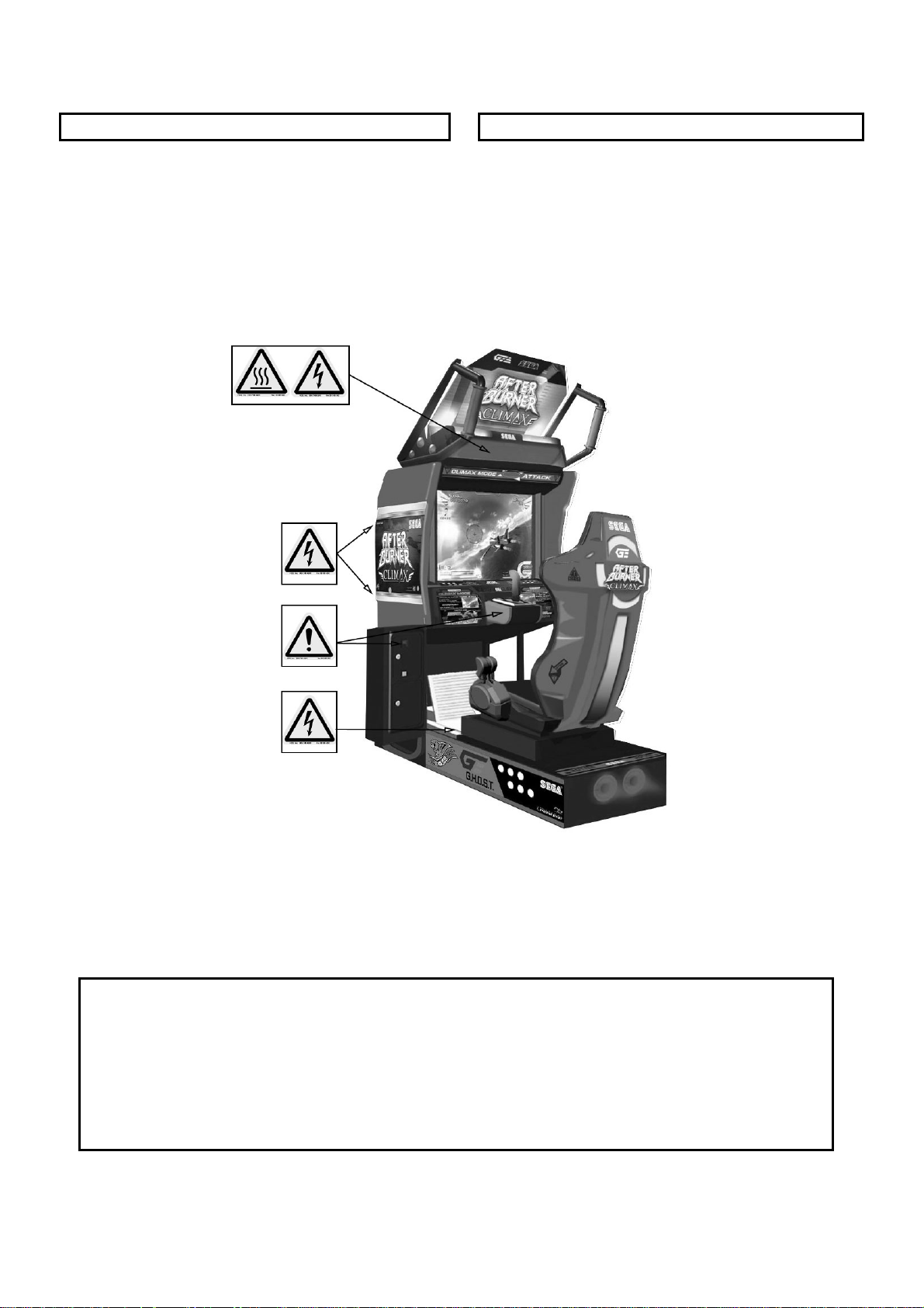
To ensure maximum safety for both customers and operators, stickers and printed instructions describing potentially
hazardous situations are applied to places where accidents could occur. Ensure that where the product is operated has
sufficient lighting to allow any warnings to be read. If any sticker or printed warning is removed or defaced, do not
operate the machine, until it has been replaced by an identical item.
When handling the monitor, be very careful. (Applies only to product with monitor)
Some of the monitor (TV) parts are subject to high tension voltage. Even after turning off the power some components
are still occasionally subject to high tension voltage. Monitor repair and replacement should be performed by qualified
service engineers only.
In cases where commercially available monitors and printers are used only the contents relating to this product are
stated in this manual. Some commercially available equipment has functions and reactions not stated in this manual.
Read this manual in conjunction with the specific manual of such equipment.
Descriptions contained herein may be subject to change without prior notification.
The contents described herein are fully prepared with due care. However, should any question arise or errors be found
please contact SEGA.
Page 4

1.1 INSPECTIONS IMMEDIATELY AFTER TRANSPORTING THE PRODUCT TO THE
LOCATION
• Inspection should only be carried out by QUALIFIED SERVICE PERSONNEL.
Normally, at the time of shipment, SEGA products are in a state to allowing usage immediately after
transporting to the location. Nevertheless, an irregular situation may arise during transportation preventing
this. Before turning on the power, check the following points to ensure that the product has been
transported safely.
• Are then any dented parts or defects (cuts, etc.) on the external surfaces of the product.?
• Are castors and leg adjusters present and undamaged?
• Do the power supply voltage and frequency requirements meet with the local supply?
• Are all wiring connectors correctly and securely connected? Unless connected in the correct direction,
connector connections cannot be made successfully. Do not insert connectors forcibly.
• Does the power cord have any cuts or dents?
• Do fuses meet the specified rating?
• Are such units such as monitors, control equipment, IC BD, etc. firmly secured?
• Are all earth wires connected?
• Are all accessories available?
• Can all doors and lids be opened with the accessory keys and/or tools?
3
Page 5
CONCERNING THE STICKER DISPLAY CONCERNING WARNING STICKERS
SEGA product has stickers describing the product
manufacture number (Serial Number) and electrical
specification. If you require service assistance you will
require the Serial Number. Identical machines may
have different parts fitted internally. Only by quoting the
Serial Number will the correct parts be identified.
SEGA product has warning displays on stickers,
labels or printed instructions adhered/attached to or
incorporated in the places where hazardous
situations can arise. The warning displays are
intended for the accident prevention of customers
and service personnel.
SPECIFICATIONS
Installation Space (mm): 945 (W) x 1625(D)
Height (mm): 1873
Weight (kg): Approx. 260
Power, Max: 430W Rated Voltage (VAC):
Rated Current (A):
230 VAC
2.2A
Operating Temperature Range 5 - 40°C
Note: Descriptions in this manual are subject to change without prior notice.
4
Page 6

2 INTRODUCTION TO THIS SERVICE MANUAL
SEGA ENTERPRISES LTD., supported by its experience in electronic high technology of VLSI’s,
microprocessors etc. and with a wealth of experience, have for more than 30 years been supplying various
innovative and popular games to the world market. This Service Manual is intended to provide detailed
descriptions together with all the necessary information covering the general operation of electronic
assemblies, electromechanicals, servicing controls, spare parts, etc. as regards MINI CLUB KART, a new
SEGA product. This manual is intended for those who have knowledge of electricity and technical expertise
especially in IC’s, CRT’s, microprocessors etc. Carefully read this manual to acquire sufficient knowledge
before working on the machine. Should there be any malfunction, non-technical personnel should under no
circumstances touch the interior systems. Should such a situation arise contact the nearest branch listed
below or our head office.
SEGA AMUSEMENTS EUROPE LTD./ SEGA SERVICE CENTRE
Suite 3A Oaks House,
12/22 West Street,
Epsom
Surrey
United Kingdom
KT18 7RG
Telephone: +44(0)1372 731820
Fax: +44(0)1372 731849
5
Page 7
3 INSTALLATION AND SERVICE INSTRUCTIONS
• Installation and commissioning should only be carried out by QUALIFIED
SERVICE PERSONNEL.
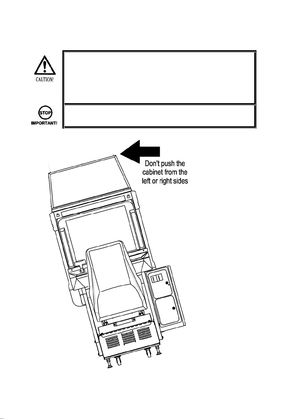
3.1 HANDLING AND INSTALLATION PRECAUTIONS
When installing or inspecting the machine, be very careful of the following points and pay attention to
ensure that the player can enjoy the game safely.
The game must NOT be installed under the following conditions:
• Outside, the game is designed for indoor use only.
• In areas directly exposed to sunlight, high humidity, dust, excessive heat or extreme cold.
• In locations that would present an obstacle in the case of an emergency i.e. near fire equipment or
emergency exits.
• On unstable surfaces or surfaces subject to vibration.
• Where liquids, other than routine cleaning (do not use water jet), may come into contact with the game.
Important:
• This machine should only be installed by Qualified Service Personnel.
• Be sure to switch the supply power OFF and remove the mains supply plug from the machine before
any work is carried out on the machine.
• Do not attempt to repair the PCB’s (Printed Circuit Boards) yourself. This will void the warranty. The
PCB’s contain static sensitive devices that could be damaged.
• Always return a faulty part to your distributor with adequate packaging and protection.
• When removing the plug from the mains always grasp the plug not the cable.
• Do not use a fuse that does not meet the specified rating.
• Make sure all connections are secure before applying power.
• Do not clean using a pressure washer.
• Ensure that the mains lead is not damaged. If the mains lead is damaged in any
way there could be a danger of electric shock or a fire hazard.
• Ensure that the power supply is fitted with circuit protection. Using the power
supply without circuit protection is a fire hazard.
3.2 COIN HANDLING
Standard Sega machines are fitted with a C120 coin mechanism, however, as a service to our customers
Sega machines can be supplied with no coin mechanism or door allowing the customer to fit a coin
handling option from the approved list. Fit only the coin handling arrangements detailed below and follow
the instructions provided. Failure to fit the coin handling options detailed or failure to follow the installation
instructions will render the machine, under the CE marking directive, void.
Approved coin handling options:
• Money Controls C220 / SR3
• Generic mechanical
• Mars (MS111B1 and ME115)
• SECI RM4-G20
6
Page 8
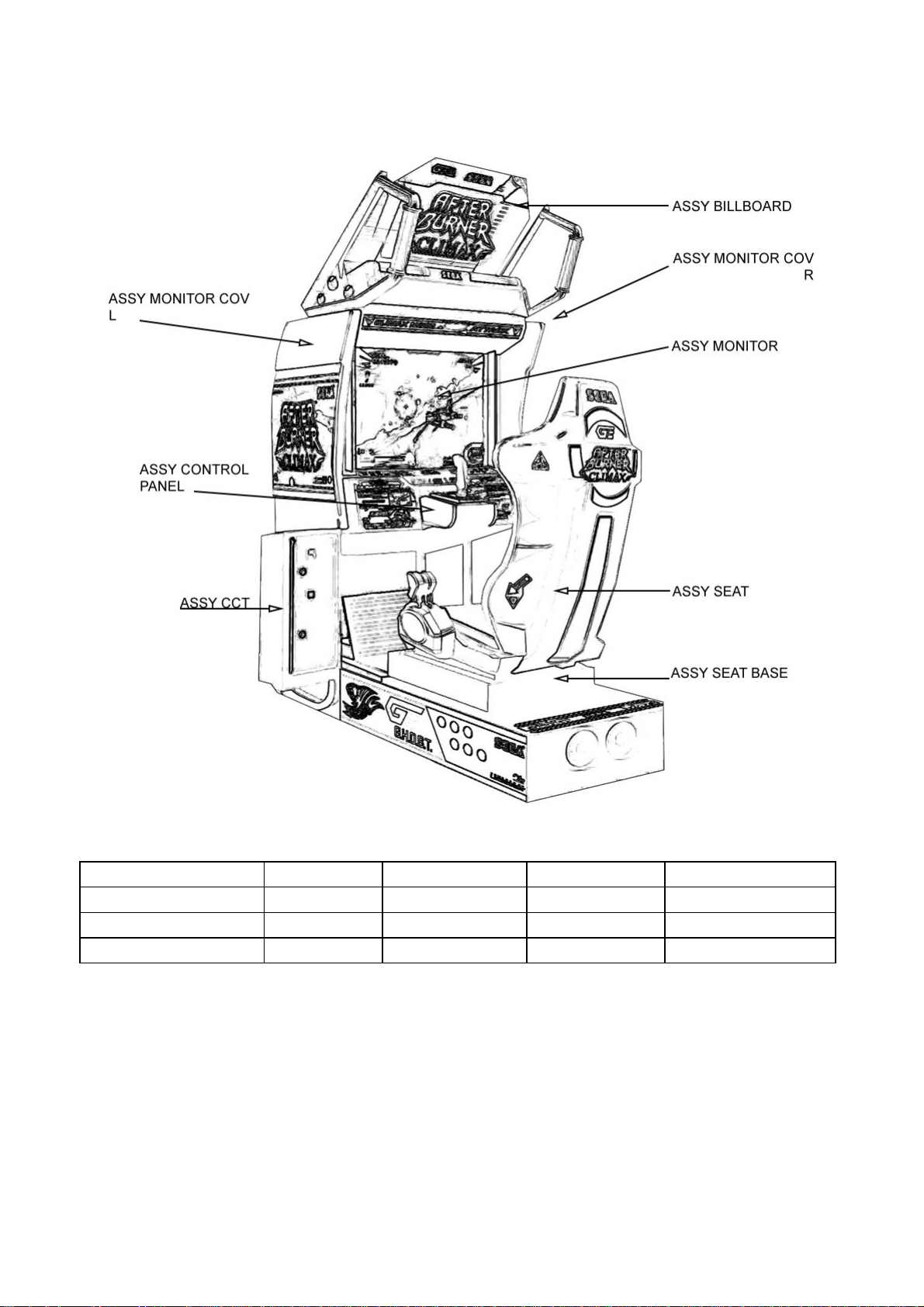
3.3 NAME OF PARTS
Width (mm) Length (mm) Height (mm) Weight (kg)
COCKPIT 945 1625 1522 239
BILLBOARD 758 560 353 13
When Assembled 945 1625 1873 Approx. 260
7
Page 9
3.4 ACCESSORIES
The machine is supplied with an installation kit. Please ensure the following parts are supplied:
3.4.1 INSTALLATION KIT
**1 ABX-2011UK INSTR CMODE L MULTI 1
**2 ABX-2012UK INSTR ATTACK R MULTI 1
**5 ECA-0001 SUPPORT BRKT 2
**6 420-0002-01UK SERVICE MANUAL ABX STD 1
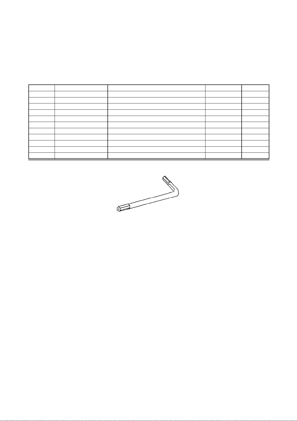
**7 540-0009-01 WRENCH M8 TMP PRF 1
**8 540-0007-01 WRENCH M5 TMP PRF 1
**9 540-0006-01 WRENCH M4 TMP PRF 1
**13 OS1019 SELF SEAL BAG 9X12.3/4 2
**14 SAECE-XXX DECLARATION OF CONFORMITY 1
**17 601-11691-92 CARTON BOX LBG 1
**104 440-CS0186UK STICKER C EPILEPSY MULTI 1
**301 600-7269-0500UK CA LAN CAT5 500CM 1
Part No. 540-0006-01, 540-0007-01, 540-0009-01 - Tamper-proof TORX wrench.
8
Page 10

3.4.2 SHIPPING THE GAME BOARD
• When returning the GAME BOARD for repair or replacement, be sure to package
the entire ASSY SHIELD CASE in the original card transit box - THERE ARE NO
USER-SERVICEABLE PARTS INSIDE.
• Failure to return the GAME BOARD in this manner may invalidate the warranty.
Pack the ASSY SHIELD CASE in the original transit box as shown. Putting it upside down or packing
otherwise in the manner not shown can damage the GAME BOARD and other parts.
9
Page 11
3.5 ASSEMBLY INSTRUCTIONS
• Perform the assembly by following the procedure herein stated. Failure to comply
with the instructions, for example, inserting the plug into an outlet at a stage not
mentioned in this manual can cause an electric shock
• Assembling should be performed as per this manual. Since this is a complex
When carrying out the assembly work, follow the procedure in the following five item sequence
machine, erroneous assembling can cause damage to the machine, or
malfunction to occur.
• Do not attempt to complete this work alone, a minimum of 2 people are required.
• Assembly should only be carried out by QUALIFIED SERVICE PERSONNEL.
STEP 1: APPLYING THE PLAY INSTRUCTIONS
STEP 2: SECURING IN PLACE
STEP 3: COIN HANDLING INSTALLATION
STEP 4: CONNECTION TO THE POWER SUPPLY
STEP 5: ASSEMBLY CHECK
Note that the parts contained within the installation kit are required for the assembly work.
10
Page 12

3.5.1 APPLYING THE PLAY INSTRUCTIONS
• This operation should only be carried out by QUALIFIED SERVICE
PERSONNEL.
Supplied in the installation kit are 2 sets of play instructions in 5 languages. Select the language of
your choice and apply in the following areas:
1. ABX-2011UK: Instructions CMODE L MULTI (on control panel)
2. 422-0870UK: Instructions ATTACK R MULTI (on control panel)
1 & 2
11
Page 13
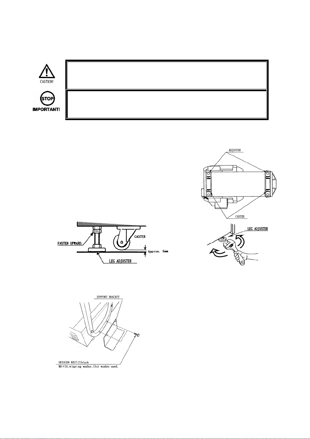
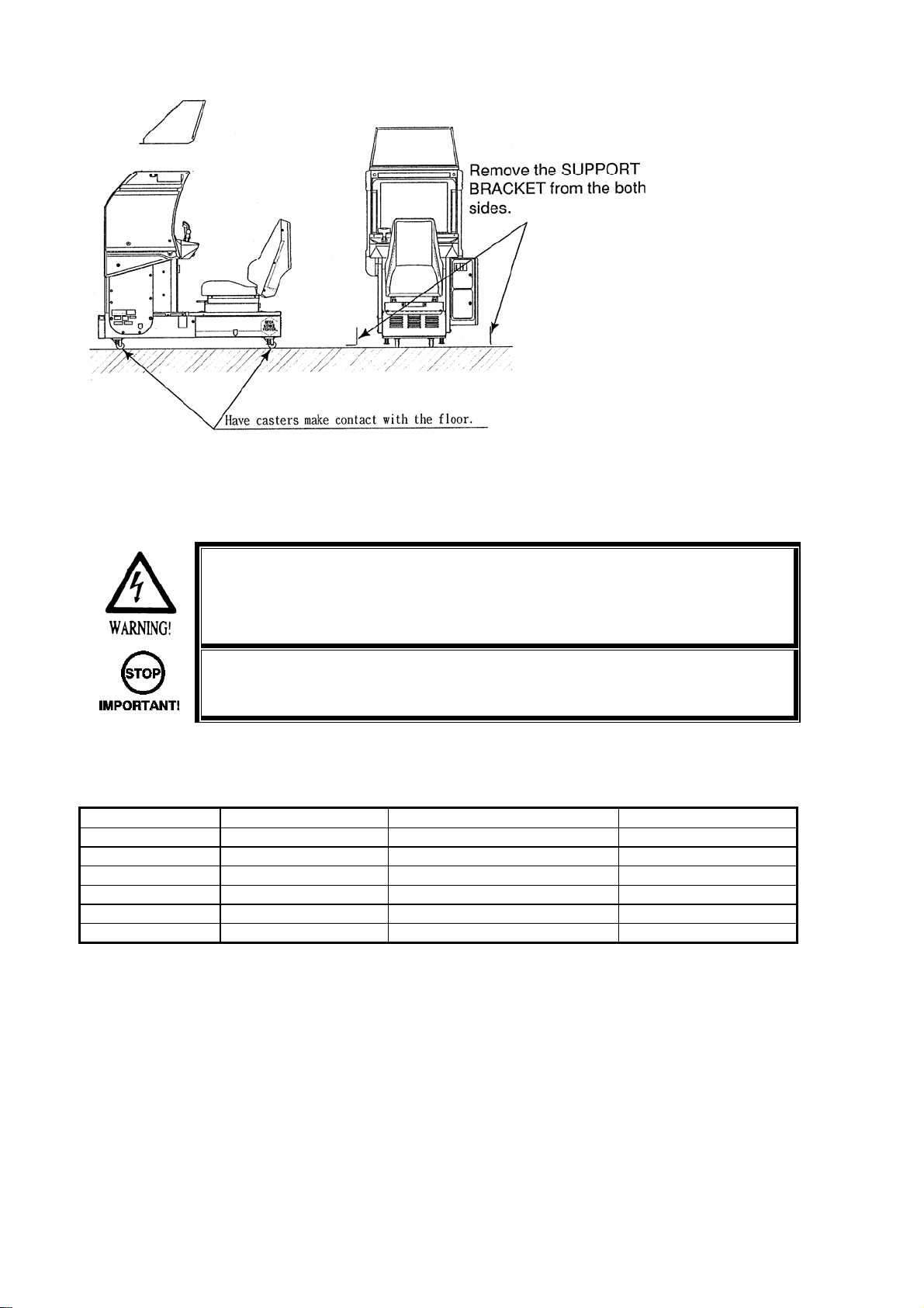
3.5.2 SECURING IN PLACE (LEG ADJUSTER ADJUSTMENT)
• Make sure all of the leg adjusters are in contact with the floor. If they are not, the
machine may move and cause injury. This operation requires 2 people.
• This operation should only be carried out by QUALIFIED SERVICE
PERSONNEL.
This machine has four castors and four leg adjusters. When the installation position is decided, unscrew
the leg adjusters so that they raise each caster a minimum of 5mm from the floor. Make sure the machine
is level.
1. Move the machine to the installation position. When installing
against or close to a wall, be sure to allow an adequate space to
allow the player access to the machine.
2. Make the leg adjusters contact the floor. Adjust using a spanner as
shown below so that a minimum of 5mm exists between the
casters and the floor. Make additional adjustment so that the
machine is level.
3. After making adjustments, fasten the lock nut upward on all four
adjusters.
4. Install the SUPPORT BRACKETS on the left and right side of the frame. Remove the two M8 bolts
shown below and replace them to secure the SUPPORT BRACKETS.
Repeat procedure for both Left and Right sided
support plates.
12
Page 14
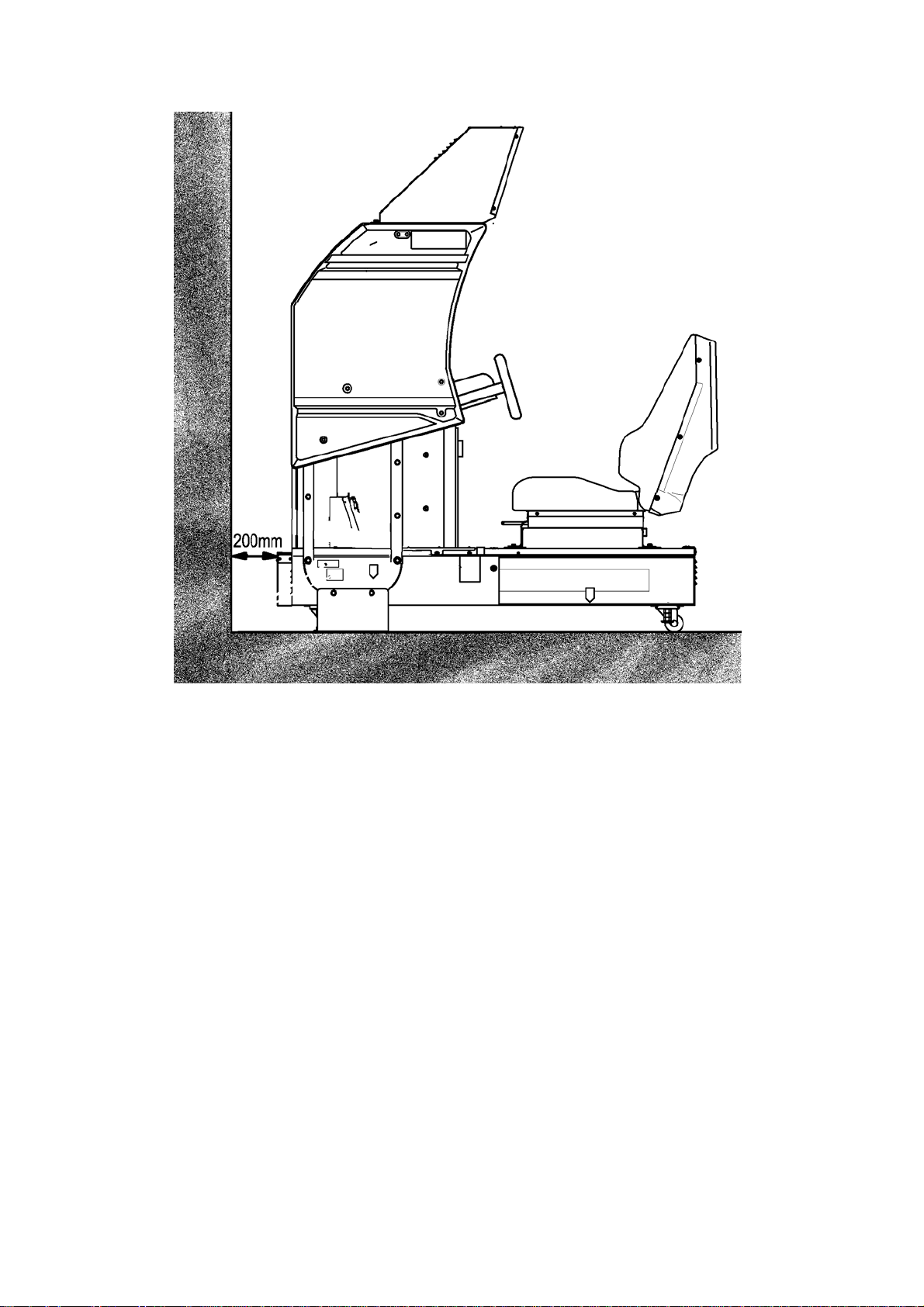
VENTILATION: Ensure adequate ventilation is maintained as detailed below:
Image shown for illustration purposes.
13
Page 15
3.5.3 COIN HANDLING INSTALLATION.
• This operation should only be carried out by QUALIFIED SERVICE
PERSONNEL.
When fitting the coin mechanism to the door please refer to the specific manufacturers installation
instructions for that coin mechanism. To fit the door to the machine, follow the procedure below.
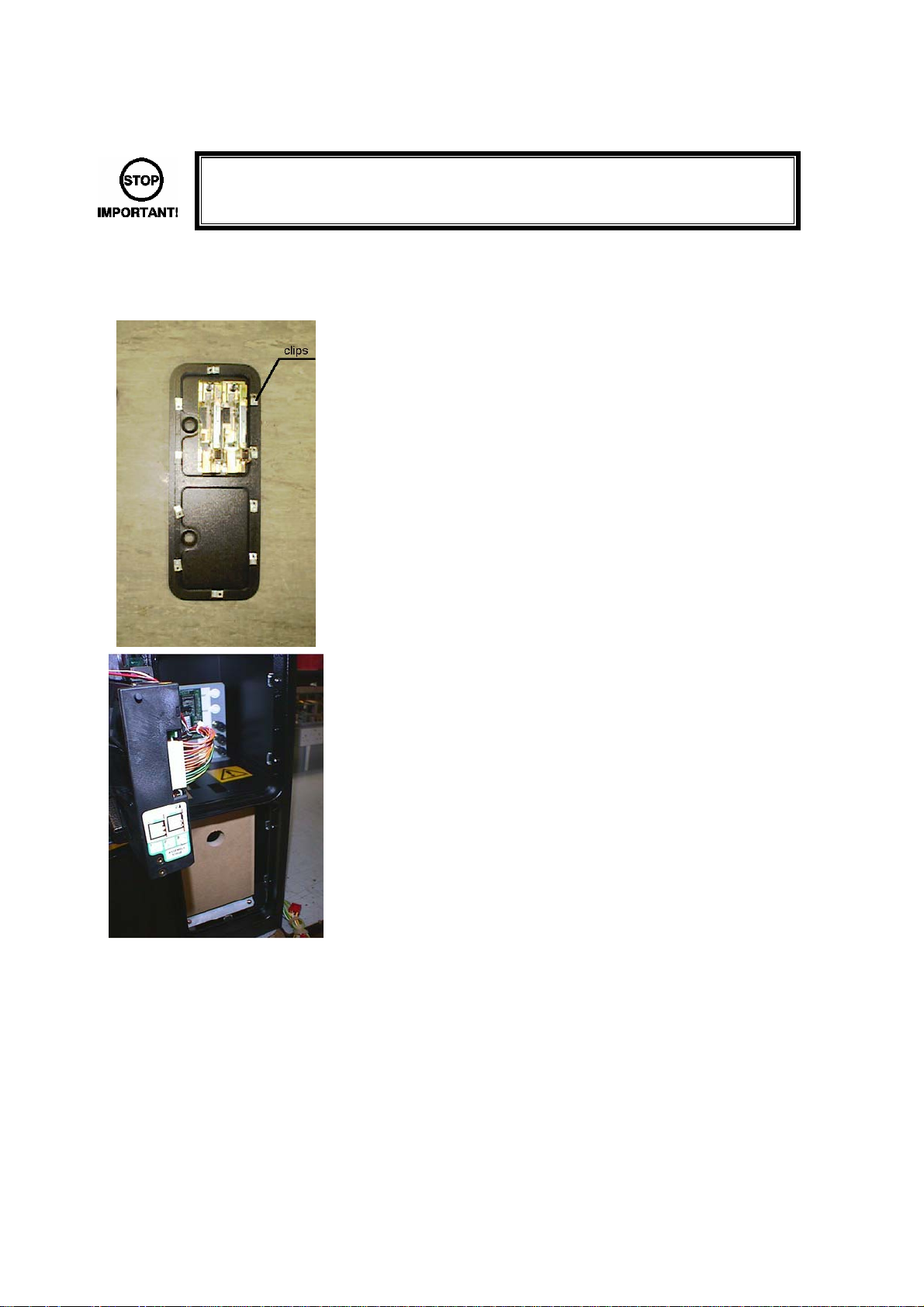
• Loosen all of the bolts on the frame which secure the clips.
• Turn all clips in towards the door.
• Position the door into the aperture in the machine.
• Turn the clips around so that they will hold the door in the
machine.
• Tighten all of the bolts.
14
Page 16
3.5.3.1 WIRING CONNECTIONS.
COIN MECH LOOM INSTALLATION
C220B LM1006IDC
LM1006LAMP-0.1
GENERIC
MECHANICAL
S
MARS
MS111B1
MARS ME115
SECI, C120 OWN LOOM AND
LM1008
LM1008-LAMP
LM1007
LM1008-LAMP
LM1006LAMP-0.1
• Attach the lamp holder to the bracket on the coin return
button.
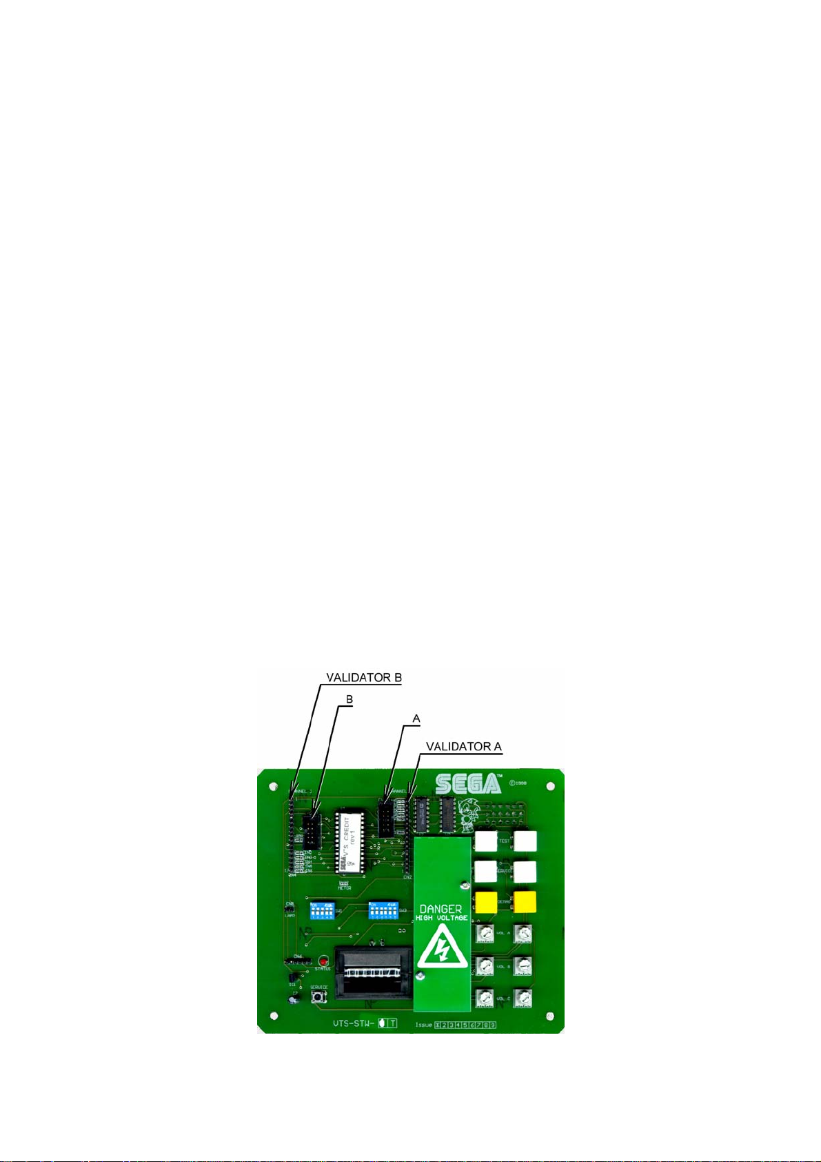
• Attach one 15-way connector to the C220 coin mech.
• Attach the other 15-way connector to Validator A on the
credit board.
• Attach the 2-way connector to ‘LAMP’ on the VTS
board.
• Fit the two lamp holders behind the coin return buttons.
• Attach the blue cable and orange cable to one mech’s
microswitch switch.
• Attach the blue/green cable and orange/green cable to
the other mech’s microswitch.
• Attach the 2-way mate and lok plug to the 2-way mate
and lok cap provided.
• Attach one 15-way connector to Validator A and the
other to Validator B on the credit board
• Fit the lamp holder to the bracket behind the coin return
button.
• Fit one of the 13-way connectors to the coin mech.
• Fit the other 13-way connector to Validator A on the
credit board. Note the 13-way connector is keyed and
this key must coincide with the key on the credit board.
• Attach the lamp holder to the bracket on the coin return
button.
• Attach the 2- connector to ‘LAMP’ on the VTS board.
• Attach the validator’s own loom to position A on the
credit board
VTS credit board assembly
15
Page 17
3.5.4 CONNECTING THE POWER
• Be sure that the machine is not already connected to the mains supply before
attempting this operation
• This operation should only be carried out by QUALIFIED SERVICE
PERSONNEL.
1. Insert the mains lead into the wall socket.
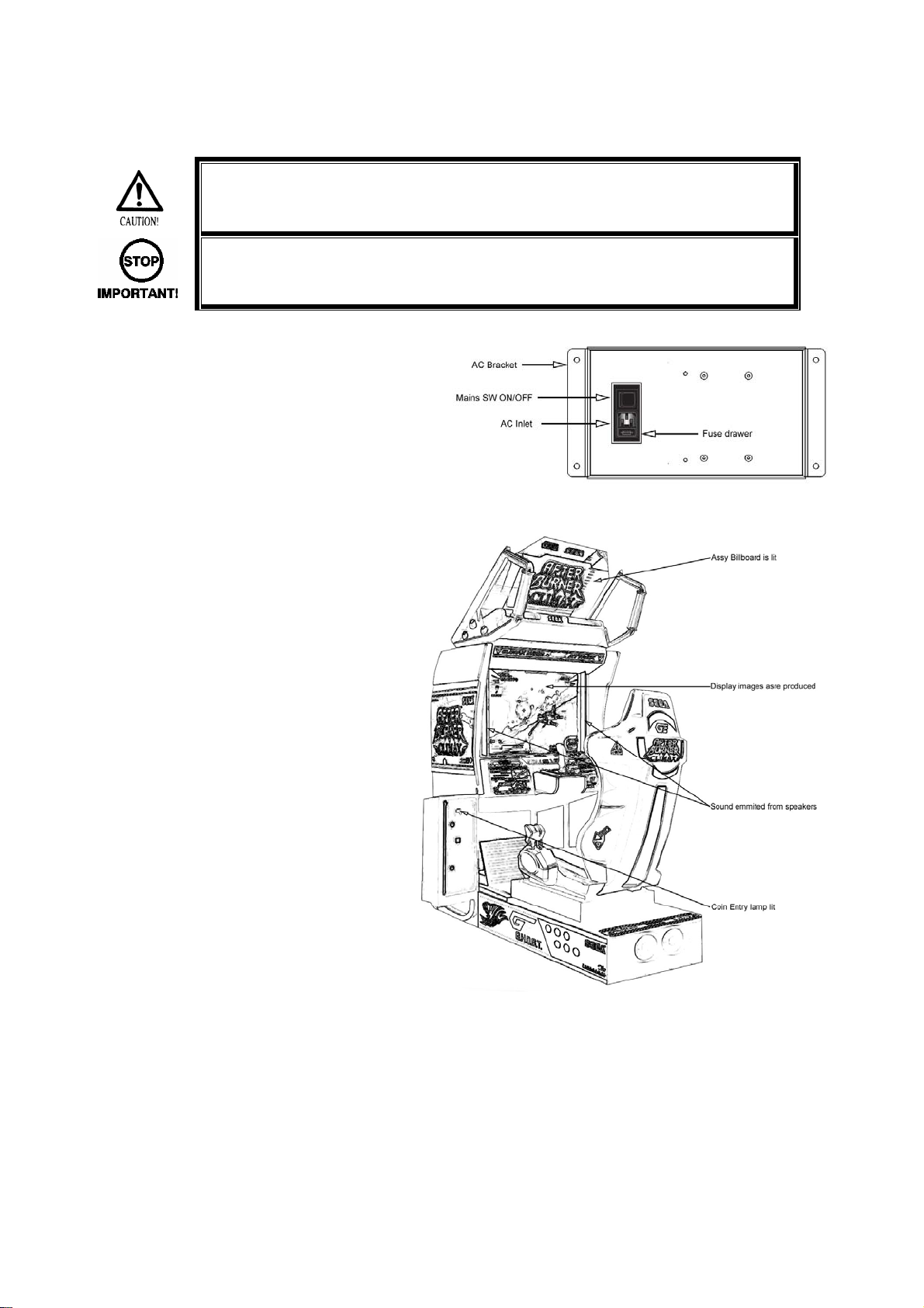
2. Insert the IEC plug into the IEC socket on the
AC bracket.
3. Switch on the power supply at the wall.
4. Switch on the mains switch on the AC bracket.
5. Once power is turned on, the fluorescent
lamps in the top and rear billboards light
up. The Start System Screen displays
after a lapse of several seconds. It is
followed by the screen that indicates that
the network is currently being checked if
the communication mode has been set. If
there is a bad or improper
communication connection, each screen
will not proceed to the next, remaining on
the currently network-checked screen. If
this occurs, resolve the error according to
the instructions in this manual.
6. If the communication mode has not been
set or the communication check ends
normally failures are displayed, if found.
Resolve the errors according to the
instructions in this document. Pressing
the Start button while a failure is onscreen allows you to go to the next
screen and start the game without
reaction.
7. Once all the above steps have been completed, the Advertise Screen displays and voices are output
through the left and right loudspeakers, unless you have set the machine so that no voices are output
during the Advertise mode.
This product retains the number of credits and the ranking data even after the power is turned off. It does
not retain data about the fractional number of coins (i.e. the number of coins not reaching one credit) or the
bonus adder count.
16
Page 18

3.5.5 ASSEMBLY CHECK
• This operation should only be carried out by QUALIFIED SERVICE
PERSONNEL.
In the TEST mode ensure the assembly has been made correctly by performing the following checks.
Use test mode to confirm that assembly is proper, and that the LINDBERGH, connecting boards, and
input/output devices are normal.
Perform the following tests in test mode.
For tests (1) to (4), refer to the LINDBERGH service manual. For tests (5) to (7), see [9-3 Game Test
Mode].
The items displayed on the test screen for tests (5) and (6) vary depending on the setting for cabinet type in
the game setting screen.
(1) Information Display Screen
When “SYSTEM INFORMATION,” “STORAGE INFORMATION,” or “JVS TEST” has been selected on the
system test mode menu, system information, game information and information on JVS I/O board
connected to LINDBERGH are displayed.
If each category of information is displayed without anomalies, the LINDBERGH is normal.
(2) JVS Input Test Screen
When “INPUT TEST” has been selected on the JVS test screen, data input to the JVS I/O board is
displayed. On the product, this is the screen for the testing coin switch.
Insert a coin. If the display to the side of the switch changes the switch and wiring connections are normal.
(3) Monitor Test Screen
When “MONITOR TEST” has been selected on the system test mode menu, the screen for checking
monitor adjustment status appears.
Monitor adjustment is completed when the product is shipped from the factory, but you should observe the
test screen to determine whether further adjustment is necessary. Refer to Chapter 10 and adjust the
monitor if necessary.
(4) Speaker Test Screen
When “SPEAKER TEST” has been selected on the system test mode menu, the screen for checking
speaker sound output appears.
To confirm that audio output is normal, have test sound output from the game unit’s speaker.
(5) Input Test
When “INPUT TEST” has been selected on the game test mode menu, the screen for testing input device
appears. Test operate the input device by pressing each switch. If the display on the side of each input
device changes to “ON” and numerical values change smoothly in accordance with each operation, the
input device and its wiring connections are normal.
17
Page 19
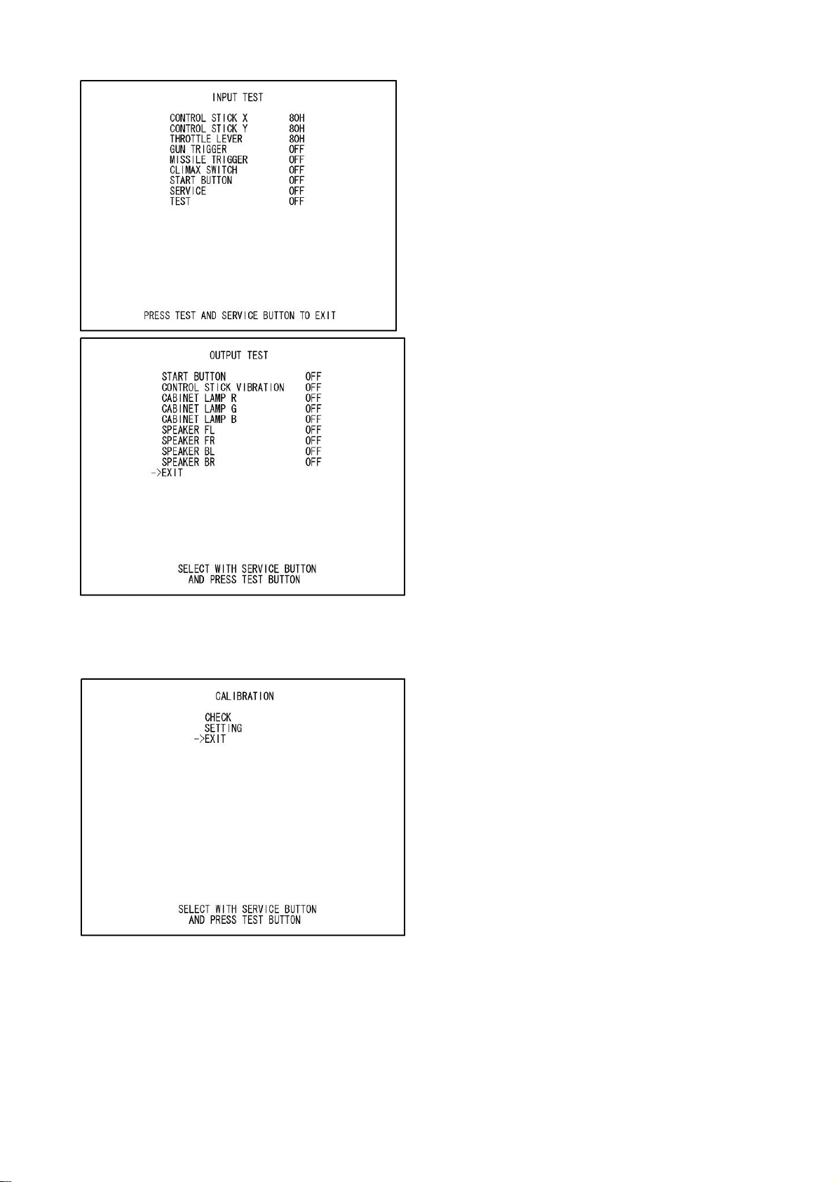
INPUT TEST SCREEN
OUTPUT TEST SCREEN
(6) Output Test
When “OUTPUT TEST” has been selected on the game test mode menu, the screen for testing lamps and
other output devices appears.
If each output device operates properly, the output device and its wiring connections are normal.
CALIBRATION SCREEN
(7) Calibration
Confirm that the operability of input devices and seat motions (Deluxe and Super Deluxe only) during game
play do not present any hindrances to play. Calibration is adjusted when the product is shipped from the
factory but it might need to be adjusted again because of vibrations during transport, etc.
If such things as operability are not satisfactory, select “CALIBRATION” on the game test mode menu and
check and adjust settings.
18
Page 20
3.6 MOVING THE MACHINE
• When moving the machine, be sure to remove the plug from the power supply.
Moving the machine with the plug inserted can cause the power cord to be
damaged, resulting in a fire or electric shock.
• When moving the machine, remove the Support Brackets, retract the leg
adjusters fully and ensure the casters make contact with the floor. During
movement pay careful attention so that the casters or leg adjusters do not
damage any other cabling laid on the floor. Such damage could result in a fire or
electric shock.
• This operation should only be carried out by QUALIFIED SERVICE
PERSONNEL.
19
Page 21
See INSTALLING THE BILLBOARD earlier in this manual for instruction.
3.7 FUSES
When transporting the
product up or down
steps, etc, disassemble
the machine as shown.
Remove the Billboard if
height is restricted (see
following page for
details).
• Never touch places other than those specified. Touching places other than those
specified can cause electric shock and short circuit. Disconnect the machine from
the supply before attempting the replacement of any fuse.
• FUSES should only be replaced by QUALIFIED SERVICE PERSONNEL.
There are a number of fuses used on this machine to protect the user and the machine from damage. Only
replace the fuse once you have removed the cause of its failure. Detailed below is a list of the fuses used,
their location and if relevant PCB reference:
PART NUMBER LOCATION TYPE & DETAILS QTY PER COCKPIT
514-5078-6300 838-14515-A0191 6.3A T CERAMIC 20MM 2
514-5078-5000 ABX-0400UK 5A T CERAMIC 20MM 1
514-5079-10000 560-LBGH-01UK 10A T CERAMIC 32MM 1
514-5078-6300 838-14551-02 6.3A T CERAMIC 20MM 2
514-5033-6300 400-5421-15024 6.3A T GLASS 20MM 1
514-5033-3000 400-5421-03012 3A T GLASS 20MM 1
There are also fuses located on the Monitor PCB. Refer to the relevant Monitor manual supplied to
reference these fuses.
20
Page 22
4 MAINTENANCE
• Maintenance must only be carried out by Qualified Service Personnel.
• Ensure that the mains power is switch OFF and disconnected before
attempting any work.
• The CONTROL PANEL ASSEMBLY is heavy and may cause injury or
damage to the machine if dropped. Use an assistant when removing and
replacing it.
• When working with the product, be sure to turn the power off. Working with
the power on may cause an electric shock or short circuit.
• Be careful not to damage the wires. Damaged wires may cause an electric
shock, short circuit or present a risk of fire.
• Do not touch any parts that are not specified in these directions. Touching
unspecified locations may lead to electric shock or cause short circuits.
• This work should be performed by site maintenance personnel or other
skilled professionals. Work performed by non-technical personnel can cause
a severe accident such as an electric shock.
• To prevent accidents while working or while operating the product after it
has been installed, be sure not to conduct any procedures other than those
given in this manual. There are cases in which procedures not covered in
this manual require special tools and skills. If a procedure not given in this
manual is required, request service from the office given in this manual or
from the point of purchase.
• Exercise due caution in performing soldering procedures. If soldering iron is
handled carelessly, there could be fires or burns.
• Proceed very carefully when heating thermal contraction tube. Careless
operations can result in fires or burns.
• In performing adjustments or replacements, check the surroundings before
powering up. The product undergoes initialization automatically after the
power has been engaged. If someone is near the product and the seat
moves left or right, there could be a collision or fall.
• When fastening plastic parts, be careful not to tighten screws and nuts
excessively. Otherwise parts may be damaged, resulting in injuries from
fragments, etc.
• Be careful not to get hand or finger caught when opening or closing the
controller lid.
• Control stick connectors are removed within a narrow cabinet. Be careful as
there is the danger of abrasions.
• While holding the control stick firmly, remove the 4 flange nuts that fasten it.
If the control stick falls on you, you could be injured.
21
Page 23
4.1 CONTROL STICK
The Control Stick unit is housed in the control panel assembly. Follow the procedure below to access the
components.
• After the volume has been replaced, be sure to set the volume value on the
test mode calibration screen and the input test screen and check variations
in the volume value.
• After adjusting or replacing a microswitch, always check ON/OFF of the
switch on the input test screen of the test mode.
• Handle parts inside the control stick very carefully. Be especially careful to
avoid damage, deformation or loss of these parts. If any one of these parts
is lost or defective, it can result in damages and/or faulty operations.
If the operability of the control stick is unsatisfactory, or if settings on the test mode calibration screen are
ineffective, the problem could be a defective mechanism, displacement of the position where volume or
microswitch has been fastened, or malfunctioning of volume or microswitch.
Carry out the following procedure to replace control stick or microswitch. Also be sure to grease the
mechanical components of the control stick once every 3 months.
4.1.1 HOW TO REMOVE THE CONTROL STICK
To replace the control stick volume or microswitch, remove the control stick. It is very difficult to work with
the control stick attached and parts or wiring could be damaged.
The following tools are needed for the following procedure.
- 2.5 mm Allen wrench or screwdriver
- 8 mm spanner, Allen screwdriver or socket wrench
1) Cut off the power.
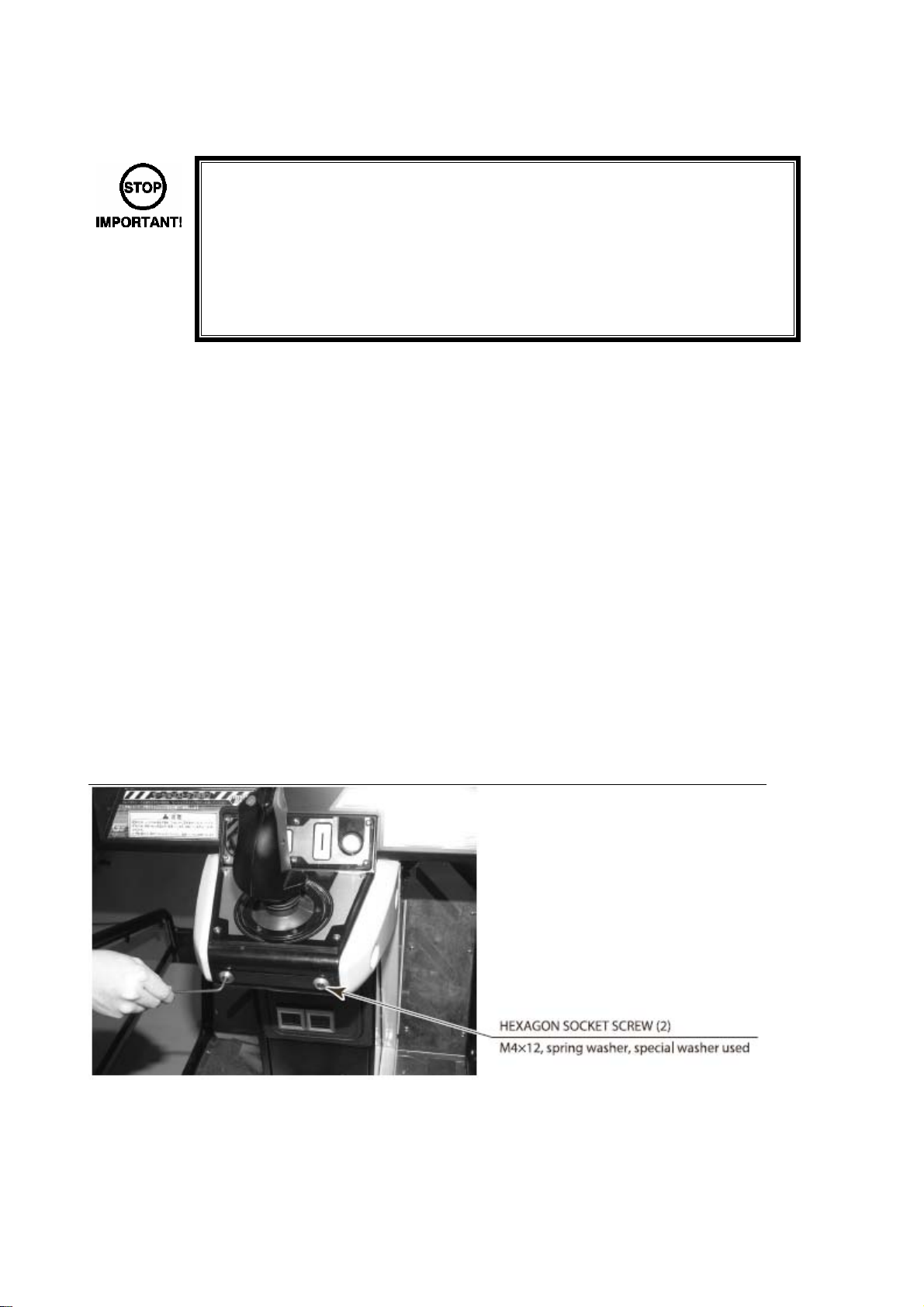
2) Remove the 2 hexagon socket screws in front of the control stick. The spring washer and special
washer are used with hexagon socket screws.
22
Page 24
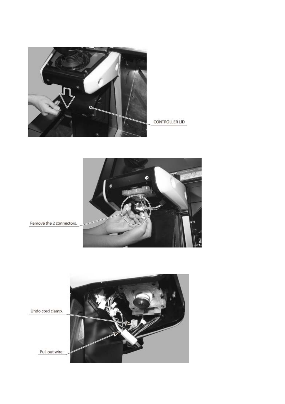
3) Open the controller lid at the bottom of the control stick
4) Remove the 2 wire connectors on the control stick.
5) On the inside of the controller lid there is a cord clamp that holds wire to the surface on the right as
you face the monitor. Undo this cord clamp and pull out the wire
23
Page 25
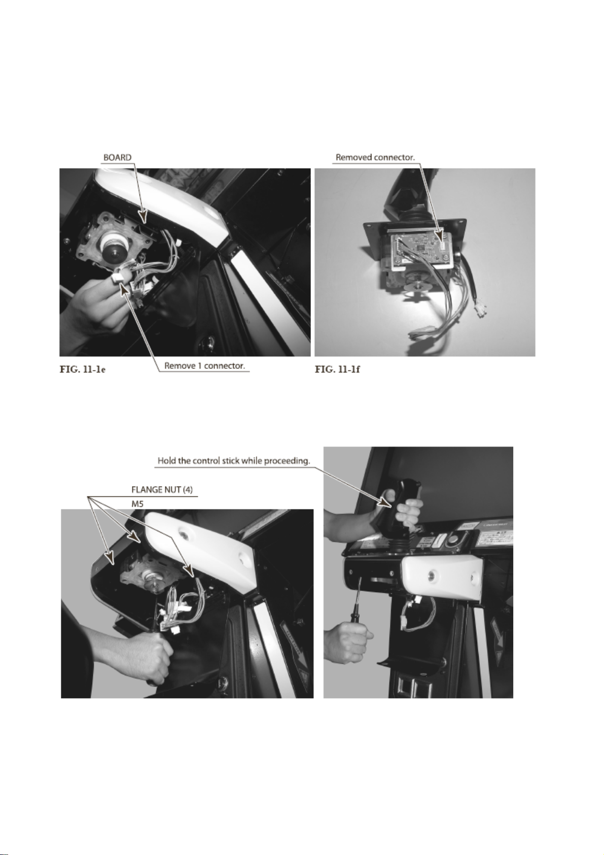
6) At the bottom of the control stick there is a board on the right side as you face the monitor. Of the
connectors connected to this board, remove the connector on the monitor side.
Be careful not to remove any connectors other than the one specified. Otherwise there could be
damages, malfunctions, faulty connections, etc.
7) Remove the 4 flange nuts that fasten the control stick from the bottom. Hold the control stick firmly
while proceeding.
24
Page 26

8) Pull the control stick downward to remove it. Be careful not to damage wiring.
4.1.2 GREASING
• Be sure to use the designated grease. Using undesignated grease can cause
parts damage.
• Do not apply grease to locations other than as specified. Doing so may create a
risk of operational problems and deterioration of parts.
• The designated periods for greasing serve only as a guide. Whenever there are
squeaks or other anomalies, apply grease at designated locations.
25
Page 27

4.1.3 VOLUME REPLACEMENT
If control stick operability is unsatisfactory and settings on the test mode calibration screen are ineffective,
the problem could be a malfunction of the control stick volume.
Remove the control stick and replace the volume.
Please note, however, that the control stick has two volumes. Make sure you are replacing the correct
volume.
Have available a volume for replacement and three thermal contraction tubes (PART NO. 310-5029-D12).
Use the following tools and solder.
- 2.5 mm Allen wrench or screwdriver
- 8 mm spanner, Allen screwdriver or socket wrench
- Philips screwdriver (for M3 screw)
- 11 to 12 mm spanner
- Nippers
- Cutter
- Wire stripper
- Soldering iron
- Industrial drier
1) Cut off the power and remove the control stick.
2) Take out the 2 screws that hold down the volume bracket
26
Page 28

3) Remove the volume together with volume bracket from the control stick.
4) Take off the hexagon nut that fastens the volume to the volume bracket, then remove the volume
from the bracket.
5) Wire connected to the volume can be used as is. Use nippers or cutters to remove old thermal
contraction tube from wire connection sites
6) Use a soldering iron to melt soldered joints and remove wire from old volume. Exercise extreme
caution in using the soldering iron
27
Page 29

7) If the length of wire exposed at the wire tip does not reach 5 mm, use wire stripper or cutter to
remove wire cover
8) Pass one wire through each thermal contraction tube.
9) Solder wire to the pin of the new volume.
Refer to wiring diagram and make sure that you are using soldering wire.
28
Page 30

10) Heat with industrial dryer and affix thermal contraction tube so that it covers soldered area
11) Attach the volume to the volume bracket, then attach this assembly to the control stick. Align the Dcut surface of the volume shaft with the D-cut surface of the hole on the side of the control stick,
then insert the shaft.
12) Fasten volume bracket with 2 screws
29
Page 31

13) Attach control stick
14) Engage the power. Note that initialization takes place.
15) Establish volume setting on the game test mode calibration screen
16) Simply changing settings on the calibration screen will not be effective. Terminate the test mode.
Note that initialization takes place upon termination of the test mode.
4.1.4 MICROSWITCH REPLACEMENT
If operability of the gun trigger is unsatisfactory, the problem could be a malfunction of the microswitch
inside the control stick grip.
Remove the control stick and replace the microswitch.
Use the following tools, solder and screw lock agent (PART NO. 090-0012).
- 2.5 mm Allen wrench or screwdriver
- 8 mm spanner, Allen screwdriver or socket wrench
- Philips screwdriver (for M4 screw)
- Soldering iron
1) Cut off the power and remove the control stick
2) Press down on the rubber cover at the base of the control stick grip.
3) Take out 3 screws and remove grip R. Be careful when removing the grip that parts inside the grip
do not come out and get lost.
30
Page 32

4) The grip L microswitch is inserted. Pull out the microswitch slowly so as not to damage wire
5) Use a soldering iron to remove wire to be connected by solder to microswitch pin.
6) Solder wire to the pin of the new microswitch.
7) Insert microswitch into grip L, then attach grip L
8) Attach grip R and fasten it with 3 screws, being careful not to let wire get caught anywhere. Coat
the screws with screw lock agent at this time. Also be careful not to tighten the screws excessively.
9) Engage the power. Note that initialization takes place
10) Check gun trigger input on the game test mode input test screen
31
Page 33

4.1.5 GUIDE PLATE REPLACEMENT
Among the potential causes of abnormal control stick operability, apart from volume malfunctions, are wear
and/or damage to guide plates.
Use the following tools to replace a guide plate.
- 2.5 mm Allen wrench or screwdriver
-4 mm Allen wrench or screwdriver
1) Cut off the power and open the controller lid at the bottom of the control stick.
2) Take out 4 hexagon socket screws that hold down the guide plate, then replace the guide plate
32
Page 34

4.2 THROTTLE LEVER
• When working with the product, be sure to turn the power off. Working with the
power on may cause an electric shock or short circuit.
• Be careful not to damage the wires. Damaged wires may cause an electric shock,
short circuit or present a risk of fire.
• Do not touch any parts that are not specified in these directions. Touching
unspecified locations may lead to electric shock or cause short circuits.
• This work should be performed by site maintenance personnel or other skilled
professionals. Work performed by non-technical personnel can cause a severe
accident such as an electric shock.
• Exercise due caution in performing soldering procedures. If soldering iron is
handled carelessly, there could be fires or burns.
• Proceed very carefully when heating thermal contraction tube. Careless
operations can result in fires or burns.
• In performing adjustments or replacements, check the surroundings before
powering up. The product undergoes initialization automatically after the power
has been engaged. If someone is near the product and the seat moves left or
right, there could be a collision or fall.
• When fastening plastic parts, be careful not to tighten screws and nuts
excessively. Otherwise parts may be damaged, resulting in injuries from
fragments, etc.
• After the volume has been replaced, be sure to set the volume value on the test
mode calibration screen and the input test screen and check variations in the
If the operability of the throttle lever is unsatisfactory, or if the lever is ineffective with the settings on the
test mode calibration screen, the problem could be faulty gear mesh or volume malfunction.
Grease the mechanical component of the throttle lever once every 3 months.
volume value.
33
Page 35

4.2.1 GREASING
• Be sure to use the designated grease. Using undesignated grease can cause parts
damage.
Once every 3 months apply grease to the spring and gear mesh that turn the volume shaft.
1) Cut off the power from the supply.
2) Remove the 4 truss screws that hold the throttle cover lower. Flat washers are used with the truss
screws.
• Do not apply grease to locations other than as specified. Doing so may create a
risk of operational problems and deterioration of parts.
• The designated periods for greasing serve only as a guide. Whenever there are
squeaks or other anomalies, apply grease at designated locations.
3) Remove throttle cover lower.
4) Apply grease only at designated locations.
5) When attaching throttle cover lower, make sure that wires do not get caught anywhere.
34
Page 36

4.2.2 VOLUME ADJUSTMENT OR REPLACEMENT
When the volume that detects throttle lever operation is unsatisfactory, either adjust the gear mesh or
replace the volume by proceeding as follows.
With this product, when the lever has been operated fully to front or rear, if the volume rotary shaft turns
within its movable range, there is no danger that the volume will be damaged. With your hand released
from the lever, fasten the volume so that the gear fits properly with the volume shaft in the designated
direction.
The following tools are required for the following procedure.
- Philips screwdriver for M4 screw
- 2 mm Allen wrench or screwdriver
- 11 to 12 mm spanner
- Nippers
- Cutter
- Soldering iron
- Industrial drier
ADJUSTMENT METHOD
1) Cut off the power supply.
2) Take out the 4 truss screws and remove throttle cover lower.
3) Loosen the 2 screws that hold down the VR bracket.
4) Adjust the gear mesh so that the volume shaft turns smoothly when the lever is manipulated and so
that the incline of the volume shaft (D cut surface direction) when hand is removed from the lever is
as shown in the illustration.
35
Page 37

5) Tighten the 2 loosened screws.
6) Turn on the power. Note that initialization takes place.
7) Check the volume value on the game test mode input test screen. (See 9-3a.) Confirm that
changes take place smoothly in accordance with lever operation. Also confirm that the value when
hand has been removed from the lever is [80H+/-4H].
8) Align the center position of throttle lever on the calibration screen.
9) Simply changing the setting on the calibration screen will not be effective. Terminate the test mode.
Note that initialization takes place when the test mode is terminated.
REPLACEMENT METHOD
Make available the volume for replacement and 3 thermal contraction tubes (PART NO. 310-5029-D20).
1) Cut off the power supply.
2) Take out the 4 truss screws and remove the throttle cover lower.
3) Unfasten the 2 cord clamps that hold down wire connected to the volume.
4) Remove the connector.
36
Page 38

5) Remove the 2 screws that fasten the VR bracket. Flat and spring washers are used with these
screws.
6) Remove the volume together with VR bracket. Be careful not to damage the wire connected to the
volume.
7) Loosen the 2 hexagon socket screws that fasten the gear. Withdraw the gear from the volume
shaft.
37
Page 39

8) Remove the nuts that fasten the VR bracket, then remove volume from VR bracket and replace.
9) The wire connected to the volume is used as is. Take away the thermal contraction tube with
nippers or cutter, melt the soldered areas with a soldering iron and remove wire from the volume.
10) Cover the soldered areas with thermal contraction tube. In place of the thermal contraction tube
that was cut away, pass each wire through new thermal contraction tube.
11) Solder the wire to the new volume. Check the wiring diagram to be sure there are no errors in
wiring.
12) Cover the soldered areas with thermal contraction tube. Heat the thermal contraction tube with an
industrial drier so that the tube adheres to soldered areas.
13) Attach the gear and VR bracket to volume.
14) After passing the wire, attach the volume. While your hand is removed from the lever, align gear
mesh so that the D cut surface of the volume shaft is level, facing directly upward, then fasten with
2 screws.
15) Manipulate the lever to check that the gear rotates smoothly.
16) Connect the connector and fasten wire with 2 cord clamps.
17) Attach the throttle cover lower. Be careful that the wire does not get caught anywhere.
18) Turn on the power. Note that initialization takes place.
19) Establish volume settings on the game test mode calibration screen. Simply changing the settings
on calibration screen will not be effective. Terminate the test mode. Note that initialization takes
place when test mode has been terminated.
38
Page 40

4.3 REPLACEMENT OF FLUORESCENT LAMPS
• When working with the product, be sure to turn the power off. Working with the power
on may cause an electric shock or short circuit.
• You may get burned by a hot fluorescent lamp or other lamps. Pay full attention to the
lamps when performing the work.
• There is the danger of short circuits or smoke generation due to deterioration of
insulation in lighting fixtures resulting from age deterioration. Check for anomalies
such as the following: Does it smell like something is burning? Is there socket
discoloration? Are any lamps being replaced frequently? Do lamps not go on
properly?
• Before turning on the power after a fluorescent lamp has been replaced, inspect
carefully to see if anyone is near the product or if tools or other items have been left
on the product. When the power is turned on, initialization takes place automatically.
If anyone is near the product, they could collide with the product or come in contact
with it accidentally. Accidents could also occur if tools or other items fly off the
product.
• Be careful when handling the plastic parts. Failure to observe this may cause injury or
damage due to fragments, etc.
• Do not attempt to replace billboard fluorescent lamps while standing on the base. If
you should misstep while working, you could stumble or fall down.
This product has 1 fluorescent lamp in the billboard
1) Cut off the power supply.
2) Remove 4 truss screws from atop the billboard.
3) Remove the billboard lid and replace the fluorescent lamp.
39
Page 41

4.4 PERIODIC INSPECTION
Once a year, check to see if power cords are damaged, the plug is securely
•
inserted, dust is accumulated between the socket outlet and the power plug, etc.
Using the product with accumulated dust in the interior may cause fire or electric
shock.
Never use a water jet, etc. to clean the inside and outside of the cabinet. If wetness
•
occurs for any reason, do not use the product until it has completely dried.
Once a year, request the office shown on this manual or the dealer from whom the
•
product was originally purchased to perform the internal cleaning. Using the
product with accumulated dust in the interior may cause fire or other accidents.
Note that you are liable for the cost of cleaning the interior parts.
Once a year, request the office shown in this manual or the dealer from whom the
•
product was originally purchased to perform routine maintenance on moving
mechanisms. Failure to perform maintenance can lead to accidents.
• There is the danger of accidents involving electrical shorts circuits or fire caused by
factors such as the deterioration of insulation in electrical and electronic equipment
over time. Check that there are no abnormalities such as odors from burning.
If there is only enough space for ventilation in the area reserved for product installation and
operation, do not begin maintenance work until space has also been set aside for
maintenance. Such work cannot be performed safely and thoroughly in narrow spaces.
In order to maintain the performance of this product and operate it safely, inspect the following items routinely
and perform maintenance.
The player directly touches and manipulates the control stick and throttle lever with his/her hands. Clean these
components as necessary and provide hand towels, etc., so that players will be comfortable while playing.
The service manual referred in the table is the LINDBERGH service manual, which is provided separately.
40
Page 42

PERIODIC CHECK TABLE
ITEMS DESCRIPTION PERIOD
CABINET
MONITOR
CONTROL STICK
THROTTLE LEVER
ROLL VOLUME
COIN SELECTOR
Confirm that adjusters contact
floor
Screen cleaning Weekly
Check screen adjustment
Inspection of volume, switch 1 month
Greasing 3 months
Inspection of volume, switch 1 month
Greasing 3 months
Inspection of volume 1 month
Greasing 3 months
Inspection of coin switch 1 month
Coin insertion test 1 month
Coin Selector cleaning 3 months
Daily
Monthly or when
moving
Check of board information 1 month
GAME BOARD
Check of settings 1 month
FLUORESCENT LAMP Inspection of lighting fixtures As appropriate
ELECTRICAL/
ELECTRONIC PARTS
POWER CABLE Inspection, Cleaning 1 year
CABINET INTERIOR Cleaning 1 year
CABINET SURFACES Cleaning As appropriate
MOVING MECHANISMS Maintenance 1 year
CLEANING THE CABINET SURFACE
When the cabinet surfaces become dirty, remove stains with a soft cloth soaked in water or diluted (with water)
chemical detergent and then wrung dry. To avoid damaging the finish, do not use such solvents as thinner,
benzene, etc. (other than ethyl alcohol) or abrasives (bleaching agent and chemical dust-cloth).
Some general-purpose household, kitchen, and furniture cleaning products may contain strong solvents that
degrade plastic parts, coatings, and print. Before using any cleaning product, read the product's cautionary
notes carefully and test the product first on a small area that is not highly visible.
Inspection As appropriate
41
Page 43

4.5 TROUBLESHOOTING
• If an error message is displayed, have the problem looked at by a store maintenance
person or a technician. Unless the problem is addressed by someone with
specialized knowledge or skills, there could be electrical shock, short circuits or fire. If
there are no store maintenance people or technicians, or moving mechanisms are
involved, cut off the power immediately and contact the office shown in this manual or
the dealer from whom the product was originally purchased.
• If problems other than those covered in this manual arise, or if no improvements can
be noted after measures given in this manual have been taken, do not take measures
indiscriminately. Cut off the power immediately and contact the office shown in this
manual or the dealer from whom the product was originally purchased. Indiscriminate
countermeasures could lead to unforeseeable accidents. They could also result in
permanent damages.
• After the cause of an error message display has been removed, before reengaging
the power or entering or leaving test mode, inspect carefully to be sure that no one is
near the product and that no tools or items have been left on the product. When the
power has been engaged or the test mode has been terminated, initialization takes
place automatically. If anyone is near the product, they could collide with the product
or come in contact with it accidentally. Accidents could also occur if tools or other
items fly off the product.
• When working with the product, be sure to turn the power off. Working with the power
on may cause an electric shock or short circuit.
• Be careful not to damage the wires. Damaged wires may cause an electric shock,
short circuit or present a risk of fire.
• After the cause of circuit protector activation has been removed, have the circuit
protector re-engaged. If the unit is used continuously as is, there could be heat
generation or fire, depending on the cause of the activation.
• If there is only enough space for ventilation in the area reserved for product
installation and operation, do not begin maintenance work until space has also been
set aside for maintenance. Such work cannot be performed safely and thoroughly in
narrow spaces.
42
Page 44

4.5.1 ERROR MESSAGES
• Apart from the error messages given below, there are errors for the LINDBERGH.
Consult the LINDBERGH service manual.
Because the seat moves, and for other reasons, this product has a unique set of error messages. These error
messages appear in the middle of the screen as shown below.
DISPLAY] Error ABX07 CONNECTION TIMEOUT
[CAUSE] Timed-out connecting to the network.
[COUNTERMEASURES] Failed to connect to the network. Check that the network cable is connected properly.
Confirm that the LINK NUM setting is not set to “1”.
DISPLAY] Error ABX08 LINK ID ERROR
[CAUSE] LINK ID is not set correctly. LINK ID is set to the same number.
[COUNTERMEASURES] An error occurred when trying to connect to the network. Set the LINK ID of 2 game
units to different numbers.
Please note that ERROR ABX01 to ABX06 suggest a cabinet movement malfunction and only refer to the
Deluxe and Super Deluxe cabinets.
• If there is an error message other than the ones below or those in the LINDBERGH
service manual, stop using the product and have the LINDBERGH sent for servicing.
43
Page 45

PROBLEMS
CAUSE
COUNTERMEASURES
When the main SW is
turned ON, the
machine is not
activated.
Billboard fluorescent
lamp does not glow.
The power is not ON.
Incorrect power
source/voltage.
The Circuit Protector of the
AC Unit functioned due to
momentary overcurrent.
The fuse of the fuse holder
was blown out due to
momentary overcurrent.
Faulty connection of
connectors
Firmly insert the plug into the outlet.
Make sure that the power supply/voltage
are correct.
After eliminating the cause of overload,
have the Circuit Protector of the AC Unit
restored.
After eliminating the cause of overload,
replace the specified rating fuse.
Join connectors securely between cabinet
and billboard.
Sounds are emitted
and the lamps are lit,
but the screen is
black.
Sound is not emitted. Sound volume adjustment
Fluorescent lamp and glow
lamp need replacement.
Faulty connections for the
visual signal connector or
the monitor power
connector.
Broken monitor.
is not correct.
Faulty connections for
various connectors.
Malfunctioning board,
amplifier and speaker.
Speaker settings are
incorrect.
Replace the fluorescent lamp and the glow
lamp.
Check the connections for the monitor and
game board connectors.
Contact the company from whom the unit
was purchased.
Adjust the switch unit's sound adjustment
volume.
Check the connections for the game board,
amp, speakers and volume connectors.
Perform output test and check.
Check the AUDIO OUTPUT setting on the
game setting screen.
44
Page 46

PROBLEMS
Irregular/uneven
colors on the monitor
screen.
Colors on the monitor
screen are strange.
The on-screen image
sways and/or
shrinks.
Does not accept
input from any switch
or volume.
Control stick or
throttle lever
operation is
unsatisfactory.
CAUSE
Magnetization of the CRT.
Faulty connection for the
visual signal connector.
Screen adjustment is not
appropriate.
The power source and
voltage are no correct.
Faulty connector
connections.
Faulty setting of volume.
COUNTERMEASURES
Press the DEGAUSS button on the
adjustment board.
Check the visual signal connector
connection and make sure it is secured
properly.
Make adjustment appropriately.
Make sure that the power supply and
voltage are correct.
Check the connection for the I/O board and
cabinet connector.
Check the power for the I/O board.
Perform calibration in test mode
Faulty volume or faulty gear
mesh installation.
Faulty connection of
connectors.
Volume malfunction. Replace the volume.
Adjust installation and check in test mode.
Check connections of control stick and
throttle lever connectors.
45
Page 47

4.6 START/ CHANGE BUTTON LAMP REPLACEMENT
• Never touch places other than those specified. Touching places other than
those specified can cause electric shock and short circuit.
1) Turn off power.
2) Remove the Control Panel as per
section
3) Have your assistant support the weight
of the Control Panel. Grasp the Switch
Body and pull from its housing.
4) Remove the lamp (bulb) from the Switch
Body and replace.
5) Refit the Switch Body and the Control
Panel in reverse order, ensuring the
wiring harnesses don’t become trapped.
46
Page 48

4.7 GAMEBOARD
• Turn off the mains power and remove the power cord before opening the
machine.
• The GAME BOARD should not require any work to be carried out upon it. All
settings and tests can be achieved without access to the GAME BOARD.
• All work to be carried out by QUALIFIED SERVICE PERSONNEL
4.7.1 REMOVING THE BOARD
To return the game board for servicing, take out the board using the following procedure.
1. Turn the main switch OFF.
2. Unlock the base and remove the 2 M6 bolts.
3. Tip the seat carefully backwards as shown. Be careful not to damage the seat back when resting it on
the floor. Use a protective mat under the seat back to protect it on hard floors.
4. Disconnect all connectors from the game board, remove the four screws securing the game board to the
wooden base and lift it out. Do not attempt to service the game board. THERE ARE NO USER
SERVICABLE PARTS INSIDE! Return the game board to the Service Department inside the special
packaging provided.
47
Page 49

4.7.2 COMPOSITION OF GAME BOARD
• Static electricity discharges can damage electronic parts on the IC Board. Take
proper anti-static precautions before opening the Shield Case Lid and starting
work. Be sure to touch grounded metallic surfaces to discharge any static
electricity.
• Do not expose the Game Board so as to avoid causing an accident or
malfunctioning.
• With the key chip inserted into it, this board serves as a special-purpose game board for the
product.
• Use with the dip switches (DIP SW) on the board at the prescribed settings. If settings do not
match the product, an error message will be displayed. In some cases, the game cannot be
started.
48
Page 50

5 GAME DESCRIPTION
The following explanations apply when the product is functioning satisfactorily. Should there be any actions
different from the following contents, some sort of faults may have occurred. Immediately look into the
cause of the fault and eliminate the cause thereof to ensure satisfactory operation.
Normally, when the power is on, the fluorescent lamp in the billboard on the monitor and the two
fluorescent lamps on the seat rear surface are lit up. In Attract Mode, such things as game content and
rankings are shown on the Attract Mode Demonstration screen on the monitor.
The colors emitted by the LEDs on the billboard right and left vary depending on the screen content.
Audio output comes from the speakers at the left and right of the monitor and the left and right of the seat
backrest. Presence or absence of audio output in the Attract Mode can be selected by means of the
settings in the test mode.
The START button on the control panel is an illuminated button. In Attract Mode, this button is not lit up.
If there are enough credits to enable play, the START button flashes. When it is pressed and the game is
started, the START button light goes out.
After the game is over, if there are enough credits to enable play, the START button flashes.
During game play, if the player takes damage during game play, the control stick vibrates.
The colors emitted by the LEDs on the billboard right and left vary depending on conditions.
49
Page 51
Game Outline
- AFTER BURNER CLIMAX is a flight shooting game that features exhilarating gameplay.
- The player takes on the role of the leader of the “Brave Fangs”, a special air-force unit whose mission is
to prevent the outbreak of all-out nuclear war.
- Fighting the enemy, you proceed through the game’s stages. Attack targets include jet fighters,
bombers, helicopters, missile launch sites and facilities.
- Using CLIMAX Mode, a special form of attack style, it is possible to take down large groups of enemies
at once.
Attract Mode
The Attract Mode cycles through the following screens.
1. Logo Display
2. Title Screen
3. Movie
4. Title Screen
5. Ranking
6. Title Screen
7. Controls
8. Title Screen
9. Demonstration
10. Return to 1
Insert a coin and press the START button during the Attract Mode and the game will start.
However, during FREE PLAY no coins need to be inserted.
Pull the trigger during the Attract Mode and it will skip to the next screen. (The Logo Display cannot be
skipped).
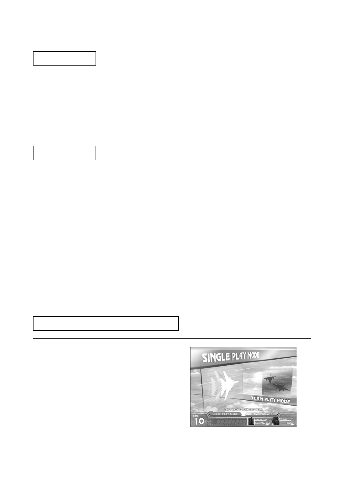
Game Mode Select (Network Play only)
Move the control stick left/right to select a game mode.
1
50
Page 52

Pull the trigger or press the START button to confirm selection.
2
ONE-PLAYER Mode:
Play for one player.
TWO-PLAYER Mode:
Two players play at the same time. Co-operate or compete to clear all stages. At each stage, scores are
compared and the winner/loser is displayed.
Aircraft Select
Move the control stick left/right to select an aircraft.
1
Push the throttle lever forward or back to change the aircraft paint pattern.
2
Pull the trigger or press the START button to confirm
3
The three following aircraft can be selected.
- F-14D Super Tomcat
- F-15E Strike Eagle
- F/A-18E Super Hornet
The four following paint patterns can also be selected.
- Standard Paint
- Camouflage
- Special Paint
- Low Visibility
Stage Composition
selection.
51
Page 53

There are a total of 21 stages.
- There are 17 basic stages (shown in squares on the above diagram)
- There are 2 secret stages (stages 06S and 10S on the above diagram)
- There are 2 extra stages (stages 14 and 15 on the above diagram)
Some stages simply have a number, like “01”, and some also have a letter included, like “04A”.
- The numbers on the above diagram denote stage number.
- Where the route splits, an “A” or “B” follows the stage number.
- Secret stages have an “S” following the number.
There are a number of routes that can be taken to the end of the game.
- In some cases the player can choose their route, and in some cases their play will automatically decide
which route is taken.
- The dotted lines on the above diagram denote a route that is automatically determined by play.
- The “No. of Stars earned” effects progress to secret stages.
- The “No. of Critical Commands completed” effects progress to the extra stages.
There are 3 endings.
- There is ENDING A, ENDING B and ENDING C, with ENDING A being the best.
- There are 15 stages to reach ENDING A and ENDING B.
- There are 13 stages to reach ENDING C.
Controls
Throttle Lever Control Stick
52
Page 54

The player aircraft is controlled by the “Throttle Lever” and “Control Stick”.
<Throttle Lever>
Used to change the speed of the player aircraft.
Pull the lever towards you to decrease speed. Push the lever away from you to increase speed.
Push the lever all the way away from you to activate CLIMAX Mode. CLIMAX Mode requires a full Climax
Gauge to activate.
<Control Stick>
Alters the movement direction of the player aircraft.
Move right to move to the right. Move left to move to the left.
Pull towards you to ascend. Push away from you to descend.
The gun trigger fires guns, and the missile trigger fires missiles.
Game Explanation
<Game Rules>
Either clearing all the stages, or all the player aircraft being lost results in Game Over.
All the player aircraft have been lost when there are no remaining player aircraft and the armor gauge falls
to 0%.
When an aircraft’s armor gauge falls to 0%, that aircraft is lost, and the remaining player aircraft are
reduced by one.
During game play, there are no increases in the number of aircraft and no restoration of the armor gauge.
The number of aircraft at the start of the game is set in test mode.
53
Page 55

<Screen Explanation>
- SCORE: Current score.
- COMBO: Current combo. Defeating enemies in quick succession results in a combo.
- MISSILE:
Remaining number of missiles. Required to fire missiles. They are
gradually replenished.
- CLIMAX GAUGE: Once this gauge is filled, CLIMAX Mode can be activated.
- SPEED GAUGE: The speed of the player aircraft.
- STAGE: Current stage number.
- STAR:
Current number of stars. Defeating many enemies without taking any
damage earns stars.
- LOCK-ON CURSOR: Align this cursor with an enemy to lock-on.
- PLAYER’S AIRCRAFT:
When there are no remaining aircraft and the armor gauge falls to 0% it is
Game Over.
- ARMOR: When the gauge falls to 0% a player aircraft is lost.
- CRITICAL COMMAND: Displays a Critical Command in progress.
<Lock-On>
54
Page 56

Using missiles is the most basic method of attack. A missile may still miss a locked on enemy if your timing
is off.
Align the lock-on cursor with an enemy to lock-on to them.
1
Fire a missile while locked on and it will home in on the enemy.
2
<After Burners>
When the throttle lever is moved to FAST (far away from you), the after burners ignite and maximum
acceleration can be realized.
The after burners can only be used for a limited period of time.
You must then return your speed to normal for a while before the after burners can be fired again.
Moving the throttle from SLOW to FAST will allow the after burners to be fired again more quickly than
normal.
<Rolling>
Rolling is a technique for avoiding missiles. Normally, missiles can be avoided by other actions. Rolling is
performed as follows.
Move the control stick left or right for a short time.
1
Move it momentarily all the way to the other side and the aircraft will roll.
2
<CLIMAX Mode>
55
Page 57

Using CLIMAX Mode allows a larger number of enemies to be locked on to and taken out at once.
During CLIMAX Mode the lock-on cursor expands, providing more opportunities to attack. You can now
quickly lock onto multiple enemies. During CLIMAX Mode, the number of remaining missile shots is
unlimited.
In CLIMAX Mode, motion can begin by pushing the throttle lever all the way to CLIMAX position, the
farthest point away from you.
The Climax Gauge must also be full before CLIMAX Mode will activate. Keeping the throttle lever pushed
all the way from you will keep CLIMAX Mode active.
CLIMAX Mode ends under the following circumstances.
- If the throttle lever is moved out of the CLIMAX position.
- If the Climax Gauge becomes totally empty.
- If damage can be taken during CLIMAX Mode.
[CLIMAX Mode Hints]
* Defeating enemies quickly is vital. The less you use the gauge up, the more often CLIMAX Mode can be
used.
* An infinite number of missiles can be used during CLIMAX Mode, presenting an opportunity to attack
even if the number of remaining missiles are low.
* A Combo increases simply by locking on and firing a missile.
56
Page 58

<TWO-PLAYER Mode>
<Game Rules>
Two players compete at the same time to get the higher score. It is also possible to co-operate to clear the
stages.
The conditions for Game Over are the same as for the one-player game.
<Evaluation>
Results (WIN/LOSE/DRAW) are determined by comparing the score earned in each stage.
MID-GAME RESULT and TOTAL RESULT display the total score comparison up until that point.
<Screen Explanation>
- RIVAL: Position and direction of your rival.
- RIVAL’S STATUS:
- DOWNED:
An icon that displays your rival’s current status.
Displayed on the right on the Player 01 screen and the left on the Player 02 screen.
(Icons are: CLIMAX Mode, Down, Game Over)
Displayed when either player is shot down.
(In red: Player 01 downed; In blue: Player 02 downed)
- PLAYER NUMBER: Player number.
57
Page 59

Route Select
Move the control stick left/right to move the cursor.
1
Pull the gun trigger to select the route.
2
Select the route you wish to take on the ROUTE SELECT screen. The countdown appears in the middle of
the screen. If the time runs out then the route that the cursor is currently highlighting shall be selected.
CONTINUE Screen
On the CONTINUE screen, select whether to continue the game or quit. The countdown appears in the
middle of the screen. If the time runs out, NO will be automatically selected.
To continue the game, perform the following before the countdown reaches 0.
<Credit Remains>
If enough credits remain to continue the game, the CONTINUE screen appears and the START button
flashes. The START button is used to select YES when there are enough credits to continue. It is also used
to select YES when FREE PLAY has been set. At any other time the START button has no effect.
58
Page 60

Move the control stick left/right to move the cursor.
1
Pull the gun trigger or press the START button to select.
2
<No Credit>
Insert coins. When a coin is inserted the count down resets to 9. When enough coins have been
inserted to continue, the START button flashes.
1
Tilt the control stick left/right and move the cursor to YES.
2
Pull the gun trigger or press the START button to select.
3
59
Page 61

Name Entry
If stage 13A, 13B or stage 15 are cleared, and the score is in the top 20 then you can enter your name.
A maximum of three characters can be entered.
Name entry ends when END is selected or when time runs out.
Move the control stick left/right to move the cursor.
1
Pull the trigger to select the letter the cursor is aligned to.
2
Pull the throttle lever towards you to move the cursor to the DEL position.
3
Press the START button to confirm the entered name.
4
If name entry ends without anything being input, the name will appear as “???”
If prohibited characters are included in the name, it will automatically be changed to “- - -”
60
Page 62

Other Notes
<Change BGM>
On the “PLEASE WAIT” screen displayed after selecting an aircraft, leave the throttle in SLOW and pull the
missile trigger to change the music to the After Burner II BGM.
<Aircraft licenses>
The rights to use all of the aircraft that appear in the game have been obtained from the appropriate
licensers.
© SEGA Corporation, 2006
Produced under license from Boeing Management Company. Boeing, McDonnell Douglas, McDonnell,
Douglas, North American Aviation, their distinctive airplane liveries, logos and product markings are among
the trademarks owned by Boeing.
Produced under a license from Northrop Grumman Systems Corporation. F-14D Super Tomcat, F-5E Tiger
II, A-10A Thunderbolt II, B-2A Spirit, and CVN-65 Enterprise are trademarks of Northrop Grumman
Systems Corp. and are used under a license to Sega Corporation.
61
Page 63

6 EXPLINATION OF TEST AND DATA DISPLAY
GAME TEST MODE
Highlight GAME TEST Mode on the SYSTEM TEST Menu Screen, and press the TEST Button to enter the
GAME TEST Mode.
Once you enter the GAME TEST Mode, the GAME TEST Menu will be displayed.
Each of the images used below display the default settings for each item.
The number of screen items will differ depending on the CABINET TYPE setting (STANDARD/DELUXE).
GAME TEST MENU
[GAME TEST Menu Screen] (test_menu.jpg)
To make a selection
Press the SERVICE Button to highlight the desired menu item with the cursor.
Press the TEST Button to perform the selected item.
(You can also use the Control Stick and Trigger to make selections in GAME TEST Mode.)
Item Explanation
a. INPUT TEST Perform an input test.
b. OUTPUT TEST Perform an output test.
c. GAME ASSIGNMENTS Set up game settings
d. NETWORK SETTING Set up network settings.
e. CALIBRATION Perform calibration.
f. BOOKKEEPING View bookkeeping records.
g. BACKUP DATA CLEAR Clear data
h. EXIT Return to SYSTEM TEST Mode.
62
Page 64

a. INPUT TEST
[!] CAUTION
During the INPUT TEST the seat will be unlocked and Sensor checks will not be performed.
Make sure that no one is standing too close, and take due care when performing the
test.
[INPUT TEST (CABINET: STANDARD) Screen] (test_input_sd.jpg)
[INPUT TEST (CABINET: DELUXE) Screen] (test_input_dx.jpg)
To make a selection
Here you can check the status of each input device. Use this screen periodically to check that all input devices are
working properly.
Press the SERVICE Button and TEST Button together to return to the GAME TEST Menu.
Menu Explanation
The number of menu items differs depending on the CABINET TYPE setting in GAME ASSIGNMENTS.
CONTROL STICK X
CONTROL STICK Y
THROTTLE LEVER
GUN TRIGGER
MISSILE TRIGGER
CLIMAX SWITCH
START BUTTON
SEAT MOTION
MOTION STOP
SEATBELT
SAFETY SENSOR LEFT
SAFETY SENSOR RIGHT
SAFETY SENSOR FRONT
SAFETY SENSOR REAR
LIMIT SENSOR LEFT
LIMIT SENSOR RIGHT
SERVICE
TEST
Check that the values change properly when the Control Stick is moved left or right.
Check that the values change properly when the Control Stick is moved forward or
back.
Check that the values change properly when the Throttle Lever is pushed forward
or back.
Working if ON when the Gun Trigger is pulled and OFF when released.
Working if ON when the Missile Trigger is pulled and OFF when released.
Working if ON when the Throttle Leaver is pushed fully away and OFF when
released.
Working if ON when the START Button is pressed and OFF when released.
Check that the values change properly when the seat is moved by hand.
Working if ON when the MOTION-STOP Button is pressed and OFF when
released.
Working if ON when the seat belt is fastened and OFF when unfastened.
Working if ON when the left Sensor is active and OFF at all other times.
Working if ON when the right Sensor is active and OFF at all other times.
Working if ON when the front Sensor is active and OFF at all other times.
Working if ON when the rear Sensor is active and OFF at all other times.
Working if ON when the seat is moved to the left limit and OFF at all other times.
Working if ON when the seat is moved to the right limit and OFF at all other times.
Working if ON when the SERVICE Button is pressed and OFF when released.
Working if ON when the TEST Button is pressed and OFF when released.
63
Page 65

b. OUTPUT TEST
[!] CAUTION
Enter OUTPUT TEST and the seat will be initialized (unless the initialization is already
complete). During the OUTPUT TEST, Sensor checks will not be performed, and the seat will
also be unlocked. Make sure that no one is standing too close and take due care when
performing the test.
[OUTPUT TEST (CABINET: STANDARD) Screen] (test_output_sd.jpg)
[OUTPUT TEST (CABINET: DELUXE) Screen] (test_output_dx.jpg)
To make a selection
Press the SERVICE Button to highlight the item you wish to test.
Press the TEST Button to perform the highlighted test.
Menu Explanation
The number of menu items differs depending on the CABINET TYPE setting in GAME ASSIGNMENTS.
START BUTTON Working if the START Button lights up when ON, and it goes off when
OFF.
CONTROL STICK VIBRATION Working if the Control Stick vibrates when ON, and stops when OFF.
CABINET LAMP R Working if the lamps lights up in red when ON, and goes off when OFF.
CABINET LAMP G Working if the lamps lights up in green when ON, and goes off when OFF.
CABINET LAMP B Working if the lamps lights up in blue when ON, and goes off when OFF.
SPEAKER FL Working if the sound comes out from the front left speaker when ON, and
stops when OFF.
SPEAKER FR Working if the sound comes out from the front right speaker when ON,
and stops when OFF.
SPEAKER BL Working if the sound comes out from the back left speaker when ON, and
stops when OFF.
SPEAKER BR Working if the sound comes out from the back right speaker when ON, and
stops when OFF.
CABINET MOVING LOCK Working if the seat locks when ON and unlocks when OFF.
CABINET MOVING LEFT Working if the seat moves left when ON, and stops when OFF.
CABINET MOVING RIGHT Working if the seat moves right when ON, and stops when OFF.
CABINET MOVING CENTER Working if the seat moves to the center when ON and stops when OFF.
EXIT Return to the GAME TEST Menu Screen.
If the AUDIO OUTPUT setting under GAME ASSIGNMENTS is set to “2CH”, the speaker items will change as
SPEAKER L Working if the sound comes out from the left speaker when ON, and stops
when OFF.
SPEAKER R Working if the sound comes out from the right speaker when ON, and
stops when OFF.
64
Page 66

c. GAME ASSIGNMENTS
[GAME ASSIGNMENTS (CABINET: STANDARD) Screen] (test_game_sd.jpg)
[GAME ASSIGNMENTS (CABINET: DELUXE) Screen] (test_game_dx.jpg)
To make a selection
Press the SERVICE Button to highlight the item you wish to set.
Press the TEST Button to alter the setting of the highlighted item.
Menu Explanation
The number of menu items differs depending on the CABINET TYPE setting in GAME ASSIGNMENTS.
DIFFICULTY Set the Game Difficulty (VERY EASY/EASY/NORMAL/HARD/VERY
HARD)
PLAYERS AIRCRAFT Set the number of player aircraft at the start of the game (1 - 9).
CABINET TYPE
CABINET MOVEMENT Turn Cabinet Movement ON/OFF.
CONTROL STICK
VIBRATION
ADVERTISE SOUND Turn sound during ATTRACT Mode ON/OFF.
AUDIO OUTPUT
EXIT Return to the GAME TEST Menu Screen.
Set the cabinet type (DELUXE/STANDARD).
NOTE: Setting this incorrectly can lead to errors in operation.
Turn Control Stick Vibration ON/OFF.
Set the speaker output (4CH/2CH)
65
Page 67

d. NETWORK SETTING
[NETWORK SETTING (LINK NUM: 1) Screen] (test_network_1.jpg)
[NETWORK SETTING (LINK NUM: 2) Screen] (test_network_2.jpg)
To make a selection
Press the SERVICE Button to highlight the item you wish to set.
Press the TEST Button to alter the setting of the highlighted item.
Menu Explanation
The number of menu items differs depending on the LINK NUM setting.
LINK NUM
LINK ID
EXIT Return to the GAME TEST Menu Screen.
Set the number of cabinets to link (1 or 2)
Set the cabinet number (1 or 2)
Make sure that the two cabinets being used are both given different numbers. If
the same number if used for both, then two-player play will not be possible.
NOTE: It is recommended that, facing the screens, the cabinet on the left is given
number 1 and the cabinet on the right is given number 2.
66
Page 68

e. CALIBRATION
[CALIBRATION Screen] (test_calibrate.jpg)
To make a selection
Press the SERVICE Button to highlight the item you wish to calibrate.
Press the TEST Button to calibrate the highlighted item.
Menu Explanation
e-1) CHECK Proceed to the Calibration Value Check Screen.
e-2) SETTING Proceed to the Calibration Screen.
e-3) EXIT Return to the GAME TEST MENU Screen.
e-1) CHECK
<*1>
<*2>
<*3>
[CHECK Screen] (test_calibrate_check.jpg)
Operation
Move the device that you wish to check the calibration values for.
Press the TEST Button to return to the CALIBRATION MENU Screen.
Menu Explanation
67
Page 69

CONTROL STICK
X
In accordance with the calibration values, MIN/MAX will be displayed in <*1> when
the minimum and maximum values are entered.
NOTE: If both MIN and MAX are not displayed then the game cannot be played
properly.
CONTROL STICK Y
In accordance with the calibration values, MIN/MAX will be displayed in <*2> when
the minimum and maximum values are entered.
NOTE: If both MIN and MAX are not displayed then the game cannot be played
properly.
THROTTLE LEVER In accordance with the calibration values, MIN/MAX/CLIMAX will be displayed in
<*3> when the minimum, maximum and CLIMAX values are entered.
NOTE: If MIN, MAX and CLIMAX are not displayed then the game cannot be played
properly.
e-2) SETTING (CALIBRATION SELECT Screen)
[CALIBRATION SELECT Screen] (test_calibrate_setting.jpg)
To make a selection
Press the SERVICE Button to highlight the item you wish to calibrate.
Press the TEST Button to proceed to the CALIBRATION Screen for the highlighted item.
Menu Explanation
e-2-1) CONTROL STICK Proceed to the CONTROL STICK CALIBRATION Screen.
e-2-2) THROTTLE LEVER Proceed to the THROTTLE LEVER CALIBRATION Screen.
e-2-3) SEAT CENTER POSITION Proceed to the SEAT CENTER POSITION ADJUSTMENT Screen.
e-2-4) EXIT Return to the CALIBRATION MENU Screen.
68
Page 70

e-2-1) CONTROL STICK
● STEP 1
[CONTROL STICK (STEP1) Screen] (test_calibrate_control_1.jpg)
STEP 1 aligns the center position for the Control Stick.
Press the TEST Button after releasing your hand from the Control Stick.
After determining the center position, proceed to STEP 2.
● STEP 2
[CONTROL STICK (STEP2-1) Screen] [CONTROL STICK (STEP2-2) Screen]
(test_calibrate_control_2.jpg) (test_calibrate_control_3.jpg)
STEP 2 aligns the MIN/MAX positions for the Control Stick.
Push the Control Stick as far as possible in all directions (left/right/forward/back).
(After moving it past a certain position, the message “PRESS TEST BUTTON TO EXIT” will be displayed.)
Then, press the TEST Button to set these MIN/MAX settings (left/right/forward/back) and return to the
CALIBRATION SELECT Screen.
69
Page 71

e-2-2) THROTTLE LEVER
● STEP 1
[THROTTLE LEVER (STEP1) Screen] (test_calibrate_throttle_1.jpg)
STEP 1 aligns the center position for the Throttle Lever.
Press the TEST Button after releasing your hand from the Throttle Lever.
After determining the center position, proceed to STEP 2.
● STEP 2
[THROTTLE LEVER (STEP2-1) Screen] [THROTTLE LEVER (STEP2-2) Screen]
(test_calibrate_throttle_2.jpg) (test_calibrate_throttle_3.jpg)
STEP 2 aligns the MIN/MAX positions for the Throttle Lever.
Push the Throttle Lever as far as possible in both directions (forward/back).
NOTE: Make sure that you do not push the lever into CLIMAX Mode when inputting the MAX value. If you do so the
game cannot be played properly.
(After moving it past a certain position, the message “PRESS TEST BUTTON TO EXIT” will be displayed.)
Then, press the TEST Button to set these MIN/MAX settings and return to the CALIBRATION SELECT Screen.
70
Page 72

e-2-3) SEAT CENTER POSITION
[!] CAUTION
On this screen Sensor checks will not be performed, and the seat will also be unlocked.
Make sure that no one is standing too close and take due care when performing the
test.
[SEAT CENTER POSITION Screen] (test_calibrate_seat.jpg)
This screen allows you to adjust the seat’s center position.
Procedure
1. Move the seat by hand into the center position.
2. Align this volume value with the CENTER value. (ADD / SUB).
80H ( 80H ) < 0>
↑ ↑
These two values must match.
<0> will display how much the value has been changed from the initial 80H.
This value can vary from – 32 to +32.
3. Leave TEST Mode and the center position will be changed.
To make a selection
Use the SERVICE Button to highlight the item you wish to set.
Press the TEST Button to perform the highlighted item.
(You can also use the Control Stick and Trigger to make selections in GAME TEST Mode.)
Menu Explanation
ADD Add 1 to the CENTER position value.
SUB Subtract 1 from the CENTER position value.
EXIT Return to CALIBRATION SELECT Screen.
71
Page 73

f. BOOKKEEPING
Displays bookkeeping information across 4 screens.
Press the TEST Button to proceed to the next screen, and to return to the GAME TEST Menu from screen 4 / 4.
[BOOKKEEPING (1/4) Screen] (test_bookkeep_1.jpg)
Menu Explanation
COIN 1 Number of coins inserted into coin chute 1.
COIN 2 Number of coins inserted into coin chute 2.
TOTAL COINS Total of COIN 1 and COIN 2.
COIN CREDITS Number of credits awarded from inserting coins.
SERVICE CREDITS Number of credits awarded with the SERVICE Button.
TOTAL CREDITS Total of COIN CREDITS and SERVICE CREDITS.
[BOOKKEEPING (2/4) Screen]
(test_bookkeep_2.jpg)
Menu Explanation
NUMBER OF GAMES Total number of games played.
TOTAL TIME Total time that power has been supplied to the cabinet.
PLAY TIME Total play time.
AVERAGE PLAY TIME Average play time.
LONGEST PLAY TIME Longest play time.
SHORTEST PLAY TIME Shortest play time.
72
Page 74

[BOOKKEEPING (3/4) Screen] (test_bookkeep_3.jpg)
Menu Explanation
TIME HISTOGRAM Total number of plays in each time bracket.
[BOOKKEEPING (4/4) Screen] (test_bookkeep_4.jpg)
Menu Explanation
NUMBER OF GAMES Total number of games.
NUMBER OF GAME START Total number of games started.
NUMBER OF CONTINUE Total number of continues.
NUMBER OF GAMECLEAR Total times the game has been cleared.
NUMBER OF GAMEOVER Total number of Game Overs.
AVERAGE NUMBER OF CONTINUE Average number of continues.
MIN NUMBER OF CONTINUE TO
Least number of continues used to clear the game.
CLEARED
AVERAGE NUMBER OF CONTINUE TO
Average number of continues used to clear the game.
CLEARD
NUMBER OF TEAM PLAY Total number of two-player games.
NUMBER OF MID-GAME ENTRY Total number of mid-game entries.
NUMBER OF MOTION STOP DURING
Number of times the MOTION-STOP Button has been pressed.
GAME
NUMBER OF SENSOR VIOLATIONS Number of times a Sensor has reacted.
(Only counted when the seat is unlocked)
73
Page 75

[BACKUP DATA CLEAR Screen] (test_backup.jpg)
CLEAR ALL BACKUP DATA
CLEAR RANKING DATA (RANK01~20)
ONLY
CLEAR RANKING DATA (RANK11~20)
ONLY
CLEAR BOOKKEEP DATA ONLY Clear only BOOKKEEPING data.
EXIT Return to GAME TEST MENU Screen.
After selecting one of the above items the following confirmation screen will be displayed.
(The screen below is displayed when CLEAR ALL BACKUP DATA is selected, but the screen is almost identical in
Clear all data (both RANKING and BOOKKEEPING).
Clear only RANKING data.
Clear only RANKING data from (rank 11 to 20 only).
other cases too.)
[BACKUP DATA CLEAR Screen] (test_backup_1.jpg)
If you wish to clear data, press the SERVICE Button to highlight YES and then press the TEST Button.
“COMPLETED” will be displayed once the data has been erased.
If you don’t wish to clear data, press the SERVICE Button to highlight NO and then press the TEST Button.
Return to BACKUP DATA CLEAR Screen.
74
Page 76

7 NETWORK PLAY
• Linking machines should only be carried out by QUALIFIED SERVICE
PERSONNEL.
• Use care to ensure wiring is not damaged.
• Do not stress/over-bend the fibre optic cables, as this will affect their
performance.
• Before starting to work, ensure that the power switch is OFF. Failure to
observe this can cause electric shock or short circuit.
• Be careful not to damage the wires. Damaged wires may cause electric
shock or short circuit or present a fire risk.
• Do not touch undesignated places. Touching places not designated can
cause electric shock or short circuit.
• This work should be performed by the site maintenance individual or other
skilled professional. Performing work with non-technical personnel can
cause electric shock.
• When linking a number of machines, be sure to supply sufficient power for
the corresponding number of machines. Be sure to secure per machine
current as stated in this manual. Failure to observe this can cause a fire
and an electric shock accident.
• The distance between game machines is limited by the length of the
network cable used, but try to separate the machines as much as possible.
If the interval between them is too short, and if a customer should fall
down, there could be a head injury or other serious accident. The interval
shown in the illustration in this manual assumes that optional items have
been attached.
Do not work in areas where there are inclines, level differences, grooves,
etc. Otherwise workers could stumble and fall or suffer other serious
accident. Also, work cannot be performed properly
.
• To perform work safely, be sure to secure the space corresponding to
number of machines to be linked. Failure to observe this can cause
accident.
• To avoid accidents, use a cable cover that will not cause patrons to trip
when laying network cables in areas of heavy foot traffic.
• To prevent accidents and acts of vandalism, cover the network cables with
the
strongest cover possible.
Up to 2 machines can be linked together for interactive play, allowing up to 2 players to play
simultaneously. Before linking be sure to check there is adequate power to supply 2 machines at once.
Also ensure power is OFF to all machines being linked.
75
Page 77

7.1.1 INSTALLATION PRECAUTIONS.
Ensure that the machines are installed with 70cm between them to allow players to get in and out of the
machines.
(Actual machines may differ slightly from the illustration).
7.1.2 CONNECTING THE COMMUNICATION CABLE
Link machines for network play by connecting the Communication Cable to the HUB of each linked
machine.
1. On each machine to be linked, turn off the
power and disconnect the IEC lead
2. Remove the 4 machine screws which secure
the lower rear cover.
3. Feed the Lan cable from one machine to
another using the access hole in the AC BKT.
4. Once connections have been established, re-fit
access place and rear cover.
76
Page 78

8 APPENDIX A - ELECTRICAL SCHEMATIC
8.1 WIRE COLOURS
THE WIRE COLOUR CODE IS AS FOLLOWS:
A PINK
B SKY BLUE
C BROWN
D PURPLE
E LIGHT GREEN
Wires other than those of any of the colours listed above will be displayed by 2 alphanumeric characters:
1 RED
2 BLUE
3 YELLOW
4 GREEN
5 WHITE
7 ORANGE
8 BLACK
9 GREY
If the right hand side numeral of the code is 0, then the wire will be of a single colour shown by the left hand
side numeral (see the list above).
Note 1: If the right hand side alphanumeric is not 0, that particular wire has a spiral colour code. The left
hand side character shows the base colour and the right hand side one, the spiral colour.
[Example] 51------------- WHITE/RED = WHITE wire with RED stripes
Note 2: The character following the wire colour code indicates the size of the wire.
K: AWG18, UL1015
L: AWG20, UL1007
None AWG22, UL1007
8.2 ELECTRICAL SCHEMATIC
The following pages contain the electrical schematic for this machine.
77
Page 79

Page 80

Page 81

 Loading...