

Page 1
OWNER'S MANUAL
STANDARD CABINET
Page 2

TABLE OF CONTENTS
BEFORE USING THE PRODUCT, BE SURE TO READ THE FOLLOWING:
TABLE OF CONTENTS
INTRODUCTION
1 HANDLING PRECAUTIONS .........................................................................1
2 PRECAUTIONS REGARDING INSTALLATION LOCATION .....................................3
2-1 LIMITATIONS OF USAGE ................................................................................................3
2-2 OPERATION AREA ..........................................................................................................4
3 PRECAUTIONS REGARDING PRODUCT OPERATION .............................5
3-1 BEFORE OPERATION .....................................................................................................5
3-2 DURING OPERATION (PAYING ATTENTION TO CUSTOMERS) ..................................6
4 PART DESCRIPTIONS ..................................................................................8
5 ACCESSORIES .............................................................................................9
TABLE OF CONTENTS
6 ASSEMBLY AND INSTALLATION ..............................................................10
7 PRECAUTIONS WHEN MOVING THE MACHINE ......................................19
7-1 MOVING THE MACHINE ................................................................................................19
8 GAME DESCRIPTION .................................................................................21
9 EXPLANATION OF TEST AND DATA DISPLAY.........................................33
9-1 SWITCH UNIT AND COIN METER ................................................................................34
9-2 SYSTEM TEST MODE ...................................................................................................35
9-3 GAME TEST MODE .......................................................................................................36
a. INPUT TEST ....................................................................................................................37
b. OUTPUT TEST ................................................................................................................38
c. GAME ASSIGNMENTS ...................................................................................................40
d. NETWORK SETTING ......................................................................................................41
e. CALIBRATION .................................................................................................................43
f. BOOKKEEPING ..............................................................................................................49
g. BACKUP DATA CLEAR ..................................................................................................52
10 MONITOR ....................................................................................................53
10-1 CAUTIONS/WARNINGS REGARDING SAFETY FOR HANDLING THE MONITOR ..53
10-2 CLEANING THE CRT SURFACES ..............................................................................55
10-3 ADJUSTMENT PROCEDURE ......................................................................................56
i
Page 3

11 CONTROL STICK ........................................................................................57
11-1 HOW TO REMOVE CONTROL STICK .........................................................................58
11-2 GREASING ...................................................................................................................59
11-3 VOLUME REPLACEMENT ...........................................................................................60
TABLE OF CONTENTS
11-4 MICROSWITCH REPLACEMENT ................................................................................64
11-5 GUIDE PLATE REPLACEMENT ..................................................................................65
12 THROTTLE LEVER .....................................................................................66
12-1 GREASING ...................................................................................................................67
12-2 VOLUME ADJUSTMENT OR REPLACEMENT ...........................................................69
13 PERIODIC INSPECTION .............................................................................73
14 TROUBLESHOOTING .................................................................................75
14-1 ERROR MESSAGES ....................................................................................................76
14-2 TROUBLESHOOTING TABLE .....................................................................................77
15 GAME BOARD ............................................................................................79
16 DESIGN RELATED PARTS .........................................................................80
17 NETWORK PLAY .........................................................................................81
17-1 NETWORK CABLE CONNECTIONS ...........................................................................81
17-2 NETWORK PLAY LINK SETTING ...............................................................................82
17-3 PRECAUTIONS IN NETWORK PLAY ..........................................................................84
18 OPTIONAL ITEMS .......................................................................................85
18-1 DOLLAR BILL VALIDATOR KIT ..................................................................................85
18-2 SECURITY BAR KIT ....................................................................................................85
19 PARTS LIST .................................................................................................86
20 WIRE COLOR CODE TABLE ......................................................................94
21 CABINET WIRING DIAGRAM ..........................................................2 PAGES
ii
Page 4
INTRODUCTION
This manual is intended to provide detailed descriptions together with all the necessary information covering the
general operation of electronic assemblies, electro-mechanicals, servicing control, spare parts, etc. for the product,
“AFTER BURNER CLIMAX.”
This manual is intended for the owners, personnel and managers in charge of operation of the product.
Operate the product after carefully reading and suffi ciently understanding the instructions.
In the unlikely event that the product does not function correctly, DO NOT allow anyone other than a technician
to touch the internal system. Turn off the power to the machine, making sure to unplug the electrical cord from the
outlet, and contact the offi ce listed below or the point-of-purchase for this product.
Use of this product is unlikely to cause physical injuries or damage to property. However, points that require special
attention are indicated by bold text, the word “IMPORTANT” and the symbol below.
Indicates important information that, if ignored, may result in the mishandling of
the product and cause faulty operation or damage to the product.
INTRODUCTION
Sega Amusements U.S.A., Inc.
800 Arthur Avenue, Elk Grove Village, IL 60007-5215, U.S.A.
TEL: 1-847-364-9787
TOLL FREE: 1-888-877-2669
FAX: 1-847-427-1065
SPECIFICATIONS
Installation space: 1,225 mm (48.2 in.) [Width] x 1,810 mm (71.3 in.) [Depth]
Height: 83”
Weight: 564 lbs
Power, maximum current: 5 A (AC 120 V, 60 Hz Area)
Monitor: 29 Type Color Monitor
NOTE: The contents herein described are subject to change without notice.
iii
Page 5

Use of GPL/LGPL software
This product can use GPL/LGPL software, which is open source software. This means that customers who purchase this
product can freely obtain, alter and pass-on the source code for this software (hereafter referred to as “the source code”).
INTRODUCTION
Downloaded this software is an indication of the customer’s agreement to the GPL/LGPL contract of use and thus the
download and all subsequent use of the source code is the full responsibility of the customer.
Furthermore this source code and the download service are provided totally as-is, with no guarantees of effectiveness,
completeness, usefulness or reliability, and our company offers no support concerning this source code.
Customers using this product who wish to obtain this source code should enter the following password on the website
below to download it.
URL: http: //amproduct-softlicense.sega.jp/
ID: amsoftwebdl
Password: segaamhd1
GPL/LGPL Contract Site
URL: http: //www.fsf.org/licenses/gpl.html
URL: http: //www.fsf.org/licenses/lgpl.html
iv
Page 6
Defi nition of ‘Site Maintenance Personnel or Other Qualifi ed Individuals’
Procedures not described in this manual or marked as 'to be carried out by site
maintenance personnel or other qualified professionals' should not be carried
out by personnel without the necessary skill or technology. Work carried out by
unqualifi ed persons may cause serious accidents, including electrocution.
Parts replacement, maintenance inspections and troubleshooting should be carried out by site maintenance personnel
or other qualifi ed professionals. This manual includes directions for potentially dangerous procedures which should
only be carried out by professionals with the appropriate specialized knowledge.
The site maintenance personnel or other qualifi ed professionals mentioned in this manual are defi ned as follows:
Site maintenance personnel:
Individuals with experience in maintaining amusement equipment, vending machines, etc., working under the
supervision of the owner/operator of this product to maintain machines within amusement facilities or similar
premises by carrying out everyday procedures such as assembly, maintenance inspections, and replacement of units/
expendable parts.
Activities to be carried out by site maintenance personnel:
Amusement equipment/vending machine assembly, maintenance inspection and replacement of units/expendable
parts.
INTRODUCTION
Other qualifi ed professionals:
Persons employed by amusement equipment manufacturers, or involved in design, production, testing or
maintenance of amusement equipment. The individual should have either graduated from technical school or hold
similar qualifi cations in electrical/electronics/mechanical engineering.
Activities to be carried out by other qualifi ed professionals:
Amusement equipment/vending machine assembly, repair/adjustment of electrical/electronic/mechanical parts.
v
Page 7

HANDLING PRECAUTIONS
1
When installing or inspecting the machine, be very careful of the following points and pay attention to ensure that the
player can enjoy the game safely.
Non-compliance with the following points or inappropriate handling running counter to the cautionary matters herein
stated can cause personal injury or damage to the machine.
• Before performing work, be sure to turn the power off. Performing the work without
turning the power off can cause an electric shock or short circuit. In the case work
should be performed in the status of power on, this manual always states to that
effect.
• To avoid an electric shock or short circuit, do not plug in or unplug quickly.
• To avoid an electric shock, do not plug in or unplug with a wet hand.
• Do not expose power cords or ground wires on the surface, (fl oor, passage, etc.). If
exposed, the power cords and ground wires are susceptible to damage. Damaged
cords and wires can cause an electric shock or short circuit.
• To avoid causing a fi re or an electric shock, do not put things on or damage the
power cords.
1
HANDLING PRECAUTIONS
• When, or after installing the product, do not unnecessarily pull the power cord. If
damaged, the power cord can cause a fi re or an electric shock.
• In case the power cord is damaged, ask for a replacement through where the
product was purchased from or the office herein stated. Using the cord as is
damaged can cause fi re, an electric shock or leakage.
• Be sure to perform grounding appropriately. Inappropriate grounding can cause
an electric shock.
• Be sure to use fuses meeting the specified rating. Using fuses exceeding the
specifi ed rating can cause a fi re or an electric shock.
• Be sure that connections such as IC BD are made properly. Insufficient insertion
can cause an electric shock.
• Specification changes, removal of equipment, conversion and/or addition, not
designated by SEGA are not permitted.
- Failure to observe this may cause a fire or an electric shock. Non-compliance
with this instruction can have a bad influence upon physical conditions of the
players or the onlookers, or result in injury during play.
- SEGA shall not be held responsible for damage, compensation for damage to a
third party, caused by specifi cation changes not designated by SEGA.
• Be sure to perform periodic maintenance inspections herein stated.
Page 8
• For the IC board circuit inspections, only the logic tester is allowed. The use of a
multiple-purpose tester is not permitted, so be careful in this regard.
1
HANDLING PRECAUTIONS
such as thinner, benzine, etc.
• Static electricity from your body may damage some electronics devices on the IC
board. Before handling the IC board, touch a grounded metallic surface so that the
static electricity can be discharged.
• Some parts are not designed and manufactured specifically for this game
machine. The manufacturers may discontinue, or change the specifi cations of such
general-purpose parts. If this is the case, SEGA cannot repair or replace a failed
game machine whether or not a warranty period has expired.
CONCERNING THE STICKER DISPLAY
This SEGA product has stickers attached describing the product manufacture No. (Serial No.) and Electrical
Specifi cations. It also has a Sticker describing where to contact for repair and for purchasing parts.
When inquiring about or asking for repairs, mention the Serial No. and Name of Machine indicated on the Sticker. The
Serial Number indicates the product register. Identical machines could have different parts depending on the date of
production. Also, improvements and modifi cations might have been made after the publication of this manual. In order
to ensure you order the correct parts, mention the Serial No. when contacting the applicable places.
• When cleaning the CRT surfaces, use a soft and dry cloth. Do not apply chemicals
CONCERNING WARNING DISPLAYS
This SEGA product has warning displays on stickers, labels and/or printed instructions adhered/attached to or
incorporated in the places where a potentially hazardous situation could arise. The warning displays are intended for
accident prevention for customers and for avoiding hazardous situations relating to maintenance and servicing work.
Some portions of the cabinet contain high voltage and may cause accidents if touched. When performing maintenance,
be very careful of the warning displays. It is especially important that any complex repair and replacement work not
mentioned herein should be performed by those technical personnel who have knowledge of electricity and technical
expertise.
In order to prevent accidents, caution any customer ignoring the warnings to cease and desist immediately.
2
2
Page 9
PRECAUTIONS REGARDING INSTALLATION LOCATION
2
This product is an indoor game machine. Do not install it outside. Even indoors,
avoid installing in places mentioned below so as not to cause a fi re, electric shock,
injury and/or malfunction.
- Places subject to rain or water leakage, or places subject to high humidity in the
proximity of an indoor swimming pool and/or shower, etc.
- Places subject to direct sunlight, or places subject to high temperatures in the
proximity of heating units, etc.
- Places filled with inflammable gas or vicinity of highly inflammable/volatile
chemicals or hazardous matter.
- Dusty places.
- Sloped surfaces.
- Places subject to any type of violent impact.
- Vicinity of anti-disaster facilities such as fi re exits and fi re extinguishers.
- The operating (ambient) temperature range is not from 5 to 30 degrees.
2-1 LIMITATIONS OF USAGE
2
PRECAUTIONS REGARDING INSTALLATION LOCATION
• Be sure to check the Electrical Specifications. Ensure that this product
is compatible with the location's power supply, voltage, and frequency
requirements. A plate describing Electrical Specifications is attached to the
product. Non-compliance with the Electrical Specifi cations can cause a fi re and
electric shock.
• This product requires a breaker and earth mechanism as part of the location
facilities. Using the product without these can cause a fi re and electric shock.
• Ensure that the indoor wiring for the power supply is rated at 15A or higher (AC
single phase 100V ~ 120V area), and 7A or higher (AC 220V ~ 240V area). Noncompliance with the Electrical Specifications can cause a fire and electric
shock.
• Be sure to use an independent power supply equipped with an earth leakage
breaker. Using a power supply without an earth leakage breaker can cause an
outbreak of fi re if a power surge occurs.
• Putting many loads on one electrical outlet can cause generation of heat and a
fi re resulting from overload.
• When using an extension cord, ensure that the cord is rated at 15A or higher (AC
100V ~ 120V area) and 7A or higher (AC 220V ~ 240V area). Using a cord rated
lower than the specifi ed rating can cause a fi re and electric shock.
Electricity Consumption:
MAX. 5 A (AC 120 V, 60 Hz)
3
Page 10
2
PRECAUTIONS REGARDING INSTALLATION LOCATION
2-2 OPERATION AREA
• Be sure to provide suffi cient space specifi ed in this manual. Do not allow objects to
block the ventilation ports. It can cause generation of heat and a fi re.
• SEGA shall not be held responsible for damage or compensation for damage to a
third party, resulting from the failure to observe this instruction.
• If the machine does not fit through the entryway to the installation location, do
not disassemble it without first consulting the instructions. The machine should
only be disassembled in accordance with the instructions listed in this manual;
do not attempt to disassemble it in any other way. Specifi c tools and adjustment
procedures are required to assemble and disassemble the mechanical parts.
Attempting to assemble or disassemble the machine without consulting the
instructions may result in accidents during assembly/disassembly and electric
shock, short circuits, and/or personal injury during operation. If the machine still
does not fit through the entryway after following the procedures in this manual,
contact your retailer or the offi ce listed in this manual.
• If the machine is still too large to fit through the entryway after following the
procedures listed in this manual, do not tip the machine on its side. Attempting to
transport the machine while it is tipped on its side may cause accidents. It may
also damage or warp parts of the machine, resulting in accidents during operation.
4
4
Page 11
PRECAUTIONS REGARDING PRODUCT OPERATION
3
To avoid injury and trouble, be sure to pay attention to the behavior of visitors and players.
3-1 BEFORE OPERATION
In order to avoid accidents, check the following before starting the operation:
• To ensure maximum safety for the players and the customers, ensure that where
the product is operated has sufficient lighting to allow any warnings to be read.
Operation under insufficient lighting can cause bodily contact with each other,
hitting accident, and/or trouble between customers.
• Be sure to perform appropriate adjustment of the monitor (projector). For operation
of this machine, do not leave monitor's flickering or deviation as is. Failure to
observe this can have a bad infl uence upon the players' or the customers' physical
conditions.
• It is suggested to ensure a space allowing the players who feel sick while playing
the game to take a rest.
• Check if all of the adjusters are in contact with the surface. If they are not, the
Cabinet can move and cause an accident.
3
PRECAUTIONS REGARDING PRODUCT OPERATION
• Do not put any heavy item on this product. Placing any heavy item on the product
can cause a falling down accident or parts damage.
• To avoid injury, be sure to provide suffi cient space by considering the potentially
crowded situation at the installation location. Insufficient installation space can
cause making bodily contact with each other, hitting accidents, and/or trouble
between customers.
• Check the control devices to make sure that there are no scratches or cracks on
parts touched by players, as such defects can cause injury to hands and fi ngers.
• Do not climb on the product. Climbing on the product can cause falling down
accidents. To check the top portion of the product, use a step ladder.
• To avoid electric shock, check to see if door & cover parts are damaged or
omitted.
• To avoid electric shock, short circuit and/or parts damage, do not put the following
items on or in the periphery of the product.
Flower vases, flowerpots, cups, water tanks, cosmetics, and receptacles/
containers/vessels containing chemicals and water.
5
Page 12
3-2 DURING OPERATION (PAYING ATTENTION TO CUSTOMERS)
To avoid injury and trouble, be sure to pay attention to the behavior of visitors and players.
3
PRECAUTIONS REGARDING PRODUCT OPERATION
• For safety reasons, do not allow any of the following people to play the game.
- Those who have high blood pressure or a heart problem.
- Those who have experienced muscle convulsion or loss of consciousness when
playing video games, etc.
- Those who have neck or spinal cord problems.
- Those who are intoxicated or under the infl uence of drugs.
- Pregnant women.
- Those who are not in good health.
- Those who do not follow the attendant’s instructions.
- Those who cannot grasp the Control Unit securely because of immobility in
fi ngers, hands or arms.
- Persons who disregard the product's warning displays.
The game cannot be played while sitting in a wheelchair.
• Even players who have never been adversely affected by light stimulus might
experience dizziness or headache depending on their physical condition when
playing the game.
• Instruct those who feel sick during play to have a medical examination.
• To avoid injury from falls and electric shocks due to spilled drinks, instruct the
player not to place heavy items or drinks on the product.
• To avoid electric shocks and short circuits, do not allow customers to put hands
and fi ngers or extraneous matter in the openings of the product or small openings
in or around the doors.
• To avoid falls and resulting injury, immediately stop the customer from leaning
against or climbing on the product, etc.
• To avoid electric shock and short circuit, do not allow customers to unplug the
power plug without a justifi able reason.
6
Page 13
• Prevent customers from sitting two at a time in the seat. This game is for one player
only. If two or more customers attempt to sit in the seat and play at the same time,
they may hit their heads, hands, or elbows, possibly resulting in serious injury.
• Customers should be warned not to place children on their laps while they play the
game. Doing so may cause the child to become trapped between the player and
the control panel and/or cause the machine to tip over.
• Immediately stop such violent acts as hitting and kicking the product. Such violent
acts can cause parts damage or falling down, resulting in injury due to fragments
and falling down.
• When entering or exiting the machine, players may trip over the base. Be sure to
warn players who do not appear to be exercising proper caution.
• Persons other than the player should not be allowed to touch the controls during
play. They may brush against or collide with the controls or the player, possibly
resulting in accidents.
3
PRECAUTIONS REGARDING PRODUCT OPERATION
• Players should be warned not to place personal effects or other objects on the
base of the machine. If the safety sensor fails to detect these items, the motion of
the machine may cause them to fl y out and strike other customers.
7
Page 14
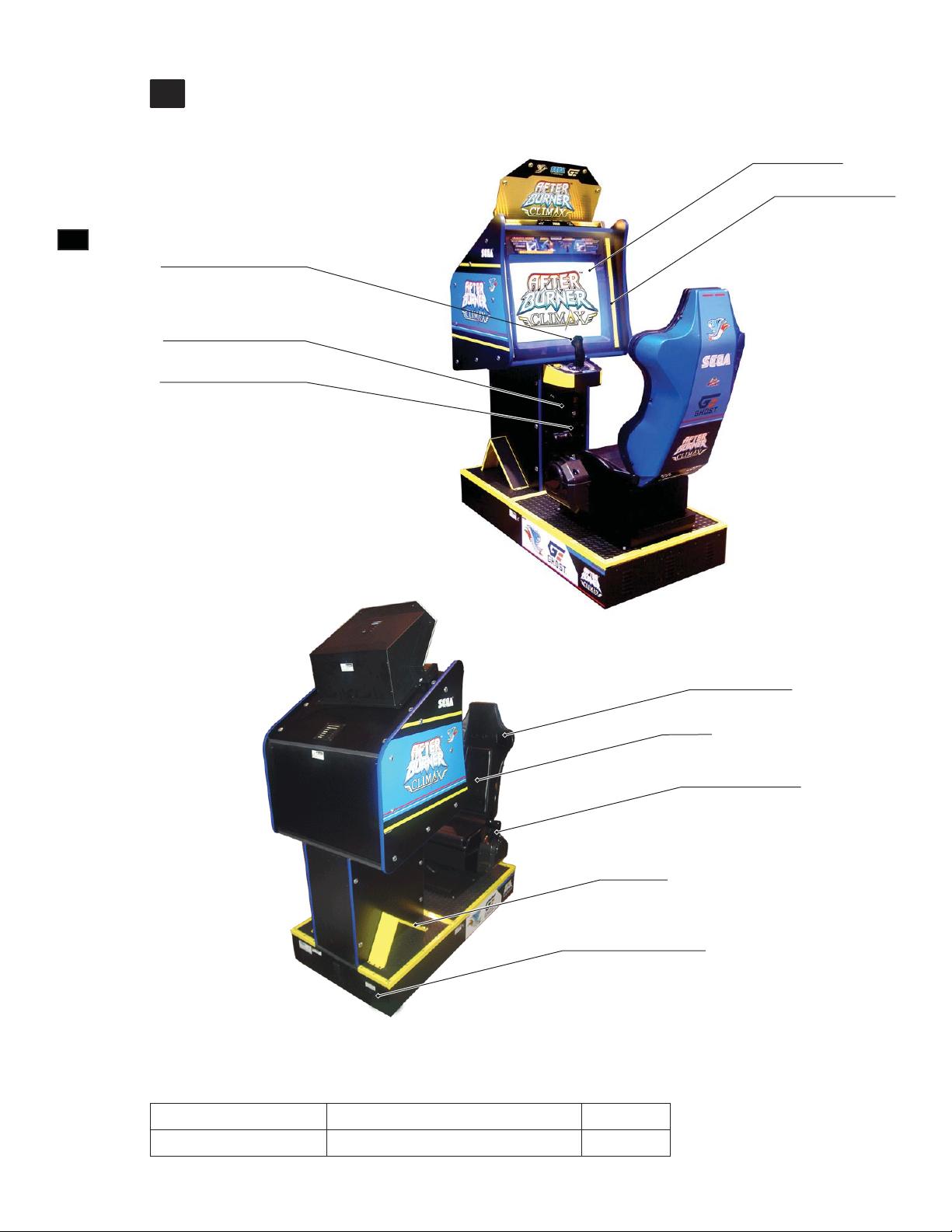
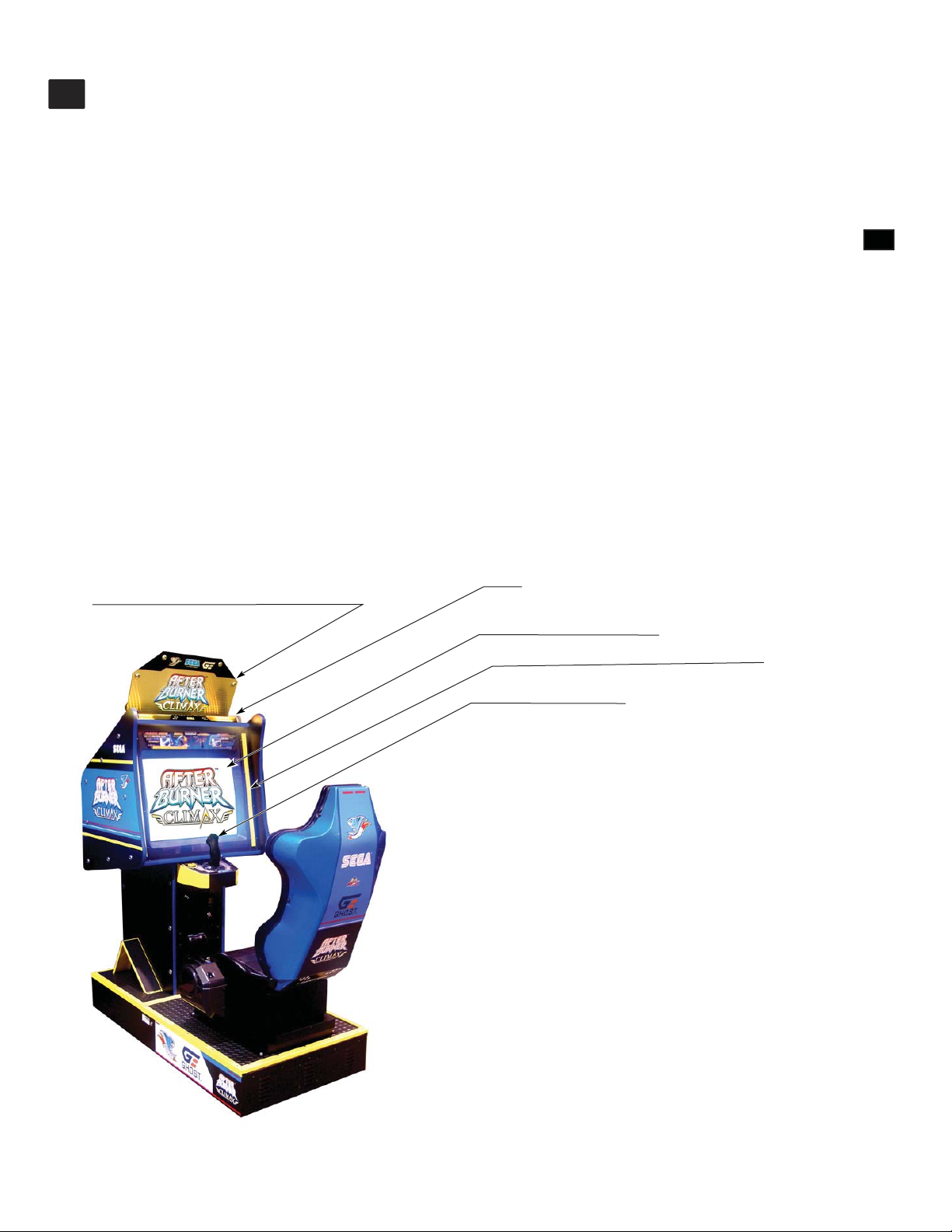
PART DESCRIPTIONS
4
29" MONITOR
FRONT SPEAKERS
(Left & Right)
4
PART DESCRIPTIONS
CONTROL STICK
COIN CHUTE DOOR
CASH BOX DOOR
REAR SPEAKER
(Left & Right)
MAIN POWER SWITCH
FIG. 4 Overall View
Dimensions
(Width x Length x Height) (Weight)
Standard Cabinet 31” x 67” x 83” 564 lbs
SEAT
THROTTLE LEVER
LEG STEP
8
Page 15
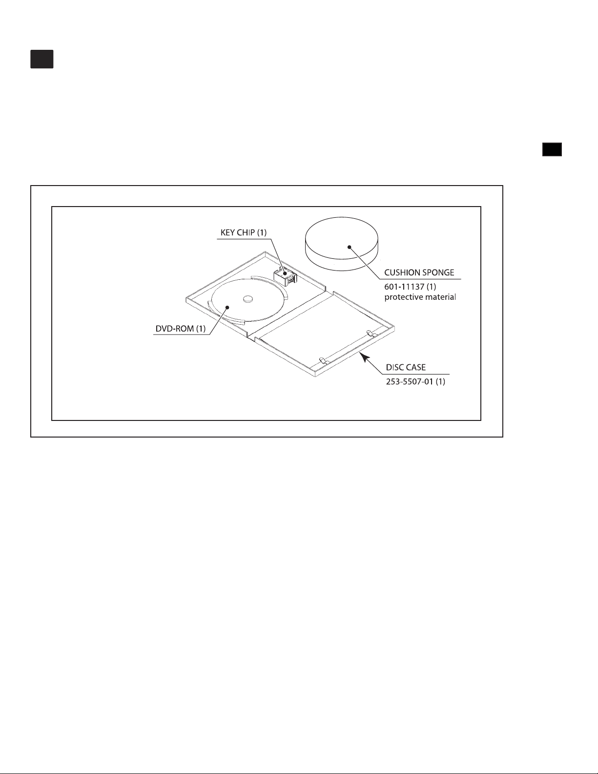
ACCESSORIES
5
MANUAL, ABX STD (1)
Part#: 525-30-300
DVD-SOFT KIT ABX (1)
Part#: 610-0727-0009
DVD KIT (1)
Software media, see 6-3.
To order the DVD-ROM by itself, use the following part number: 610-0726-0009: DVD SOFT ABX
5
ACCESSORIES
KEY CHIP (1)
CUSHION SPONGE
601-11137 (1)
protective material
DVD-ROM (1)
DISC CASE
253-5507-01 (1)
9
Page 16
6
ASSEMBL Y AND INST ALLATION
ASSEMBLY AND INST ALLATION
6
• Perform assembly work by following the procedure herein stated. Failure to comply
with the instructions can cause electric shock.
• Perform assembling as per this manual. Since this is a complex machine, incorrect
assembling can cause an electric shock, machine damage and/or improper
functioning as per specifi ed performance.
• When assembling, more than one person is required. Depending on the assembly
work, there are some cases in which working by one person alone can cause
personal injury or parts damage.
• Ensure that connectors are properly connected. Improper connections can cause
electric shock.
• Be careful not to damage the wires. Damaged wires may cause electric shock or
short circuit or present a risk of fi re.
• This work should be carried out by site maintenance personnel or other qualifi ed
professionals. Work performed by non-technical personnel can cause a severe
accident such as electric shock. Failing to comply with this instruction can cause
a severe accident such as electric shock to the player during operation. If no one
with proper technological expertise is available, request service from the office
indicated in this document or the point of purchase so as to ensure safety.
• Provide sufficient space so that assembling can be performed. Performing work
in places with narrow space or low ceiling may cause an accident and assembly
work to be diffi cult.
• To perform work safely and avoid serious accident such as the cabinet falling
down, do not perform work in places where step-like grade differences, a ditch, or
slope exist.
• If the machine is placed so that people will be passing through the vicinity, leave
at least 28” of space around the machine. If this space is too narrow, persons other
than the player may brush against or collide with the machine, possibly resulting in
accidents.
• Do not leave power cords, ground wires, or network cables exposed in areas
of heavy foot traffic. Doing so may cause them to become damaged, possibly
resulting in electric shock and/or short circuits. When laying wiring across the fl oor,
always use safety covers to protect the wires. (Wiring diameter: power cable approx. Ø 8; network cable - approx. Ø 5)
• Have a fl ashlight or another supplementary lighting unit available while working.
With indoor lighting alone, the cabinet interior may be too dark. Working without
proper lighting can lead to accidents. It also hinders proper work performance.
10
Page 17
• The cabinet has ventilation ports. Be sure not to block them. If they are blocked,
heat can build up, leading to fi re. This can also accelerate wearing of parts and
malfunctions.
• Secure ample ventilation space around the cabinet. If heat builds up, there could
be accidents associated with heat or smoke generation.
• If two cabinets are installed in alignment, make sure that there is ample distance
between them so that players or other customers will not come in contact or
collide with each other. If the distance is too narrow, there could be contacts or
collisions. If someone should fall down, head injury or other serious accident could
occur. Trouble between customers could also arise.
• Handle molded parts with care. Excessive weight or pressure may cause them to
break and the broken pieces may cause injury.
• When attaching or removing doors or lids, be careful that your hand or fi nger does
not get caught in anything.
6
ASSEMBL Y AND INST ALLATION
Be careful not to damage parts surfaces. In some cases, if such surfaces are
damaged, the part must be replaced; it cannot be reinforced or repaired.
Installation and assembly of this product should take place in the following sequence.
1 FIXATION TO INSTALLATION SITE
2 CONNECTION OF POWER AND GROUND
3 ENGAGEMENT OF POWER SUPPLY AND SOFTWARE INSTALLATION
4 ENGAGEMENT OF POWER SUPPLY AFTER INSTALLING SOFTWARE
5 CONFIRMATION OF ASSEMBLY
11
Page 18
6
ASSEMBL Y AND INST ALLATION
1 FIXATION TO INSTALLATION SITE
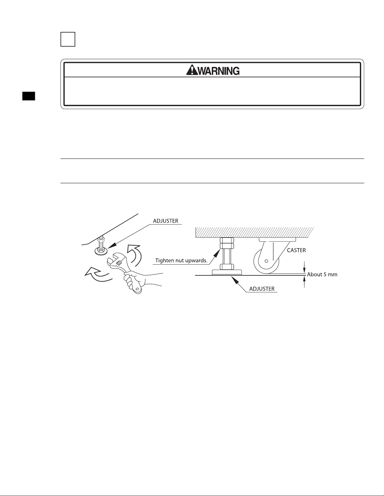
Make sure that all the adjusters contact the fl oor. Otherwise the cabinet could move,
causing an accident.
The product comes with casters attached at 4 locations and adjusters at 4 locations. When the installation site has been
determined, have the adjusters come in direct contact with the fl oor. Establish a gap of about 5 mm between the fl oor and
the casters and adjust the unit so that it will remain level.
Move the product to the installation site. If the product is to be installed near a wall, secure enough passageway
1
2
space for players to access the seat.
Use a wrench to set adjuster heights so that the unit will stay level. After setting, turn adjuster nuts upwards to
tighten them and secure adjuster heights.
12
FIG. 6-1a Illustration of Adjuster Setting
Ventilation Space
When installing the product next to a wall or other game unit, where customers will not be able to pass, secure 10”
(250 mm) of ventilation space between the product and the wall or game unit, as viewed from the left side facing
the monitor.
Page 19
2 CONNECTION OF POWER AND GROUND
• Use the power supply equipped with an earth leakage breaker. Use of power
supply without such a breaker could result in fi re if there is a current leakage.
• Have available a securely grounded indoor ground terminal. Without proper
grounding, customers could be electrocuted and product operations might not
always be stable.
• Do not expose the power cord. If these are exposed, customers could stumble
over them, for instance, and easily damage them. Additionally, if these lines are
damaged, there could be a risk of electrical shock or short circuit. Set these lines
at locations where they will not interfere with customer traffi c, or attach covers to
them.
• After laying out the power cord on the floor, be sure to always protect it. If the
power cord is left exposed, it can easily be damaged, resulting in electrical shock.
6
ASSEMBL Y AND INST ALLATION
Insert the power cord plug into a “power outlet with ground terminal.” If there is no “power outlet with ground
terminal,” be sure to establish ground by some other means; for example, by connecting the AC unit ground terminal to a
ground wire with a ground mechanism prepared separately. If you use a conversion adapter sold on the market to supply
power, connect the ground wire terminal of the adapter to a “securely grounded ground terminal.”
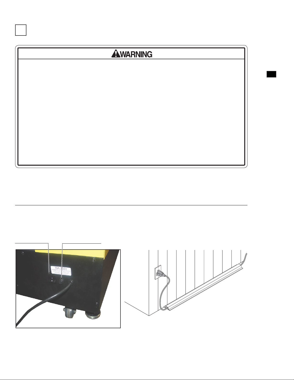
Confi rm that the main switch is at OFF. Fully insert the power cord connector on the side opposite the power
1
Main power switch
plug into the AC unit inlet. Fully insert the power cord plug into the outlet. The power cord is laid out indoors.
Protect the power cord by attaching wire cover to it.
Main Fuse, (10A, 250V)
FIG. 6-2a View, Front bottom cabinet
FIG. 6-2b
13
Page 20
6
ASSEMBL Y AND INST ALLATION
3 ENGAGEMENT OF POWER SUPPLY AND SOFTWARE INSTALLATION
• Be careful not to damage the DVD wire by getting it caught between objects, etc.
Doing so may cause a short circuit or fi re.
• The following explanation assumes that the product has been assembled properly
as explained above. If there is an error or if the product operates in a manner other
than as indicated below, cut off the power supply immediately. Failure to do so
may result in a fi re or electrical shock.
• If you look directly at the laser beam in the DVD DRIVE, you could suffer vision
impairment. Do not look inside the DVD DRIVE.
• The software is not installed on the game board (LINDBERGH) when the power
supply is engaged, so the “Error 22” message is not a malfunction. However, if there
is another error display, or if there is no video output at all, there might have been
an error in product assembly, wiring connections might be faulty, or the LINDBERGH
might not be functioning properly.
• After the power supply is engaged, wait for “Error 22” message to be displayed. If
the product is indiscriminately operated in any way beforehand, there could be
unexpected problems or malfunctions, as well as damage to parts.
• Once “Error 22” is displayed, set the DVD-ROM in the DVD DRIVE and re-engage
the power supply. Installation takes place.
• After the power supply is engaged, the DVD DRIVE tray will not come out for about
30 seconds even if you press the switch. This is due to DVD DRIVE initialization.
• The DVD DRIVE tray can come out or return only while the power supply is
engaged. The tray cannot be opened or closed while the power is off.
• Even after the software has been installed, store the DVD software kit, DVD DRIVE
and DVD wire in a secure location.
• If for any reason installation cannot be completed, an error is displayed. Refer to
the service manual and take corrective action.
14
Page 21
Use 2 Keys and 2 scrws off to open bottom seat then view DVD Drive inside of Base cabinet.
Before engaging the power supply, be sure that no one is on the base and that there are no tools, etc., on the seat.
1
When the product is shipped from the factory, the software has not yet been installed. But when the software is
installed and the power supply is engaged, the seat will move left and right.
Turn the main switch of the AC unit to ON and engage the power supply.
2
The LINDBERGH start-up screen appears. Wait for at least one minute. The error state is established. Check
3
to be sure it is “Error 22.” If it is “Error 22,” proceed to the next operation. If it is not “Error 22,” refer to the
LINDBERGH service manual and take corrective action.
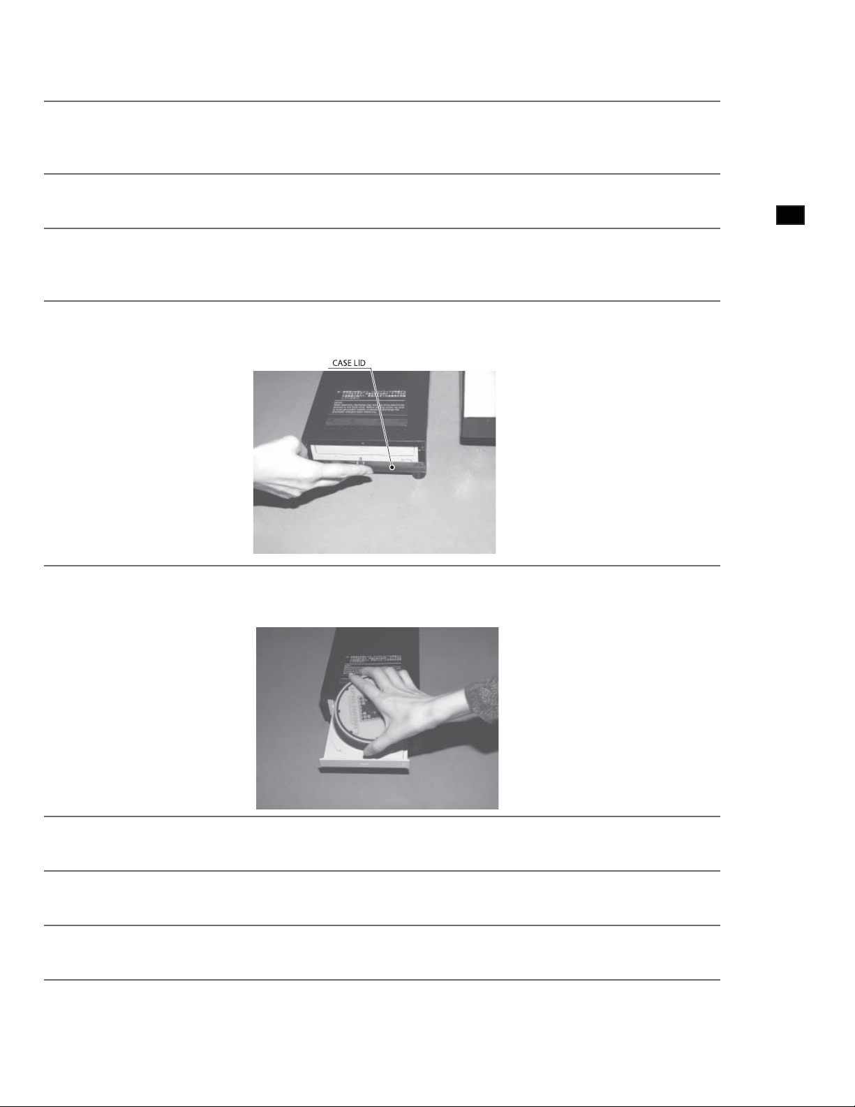
Take out 1 urea (plastic head) screw and remove the DVD DRIVE case lid.
4
6
ASSEMBL Y AND INST ALLATION
5
6
7
8
FIG. 6-3a
Press the DVD DRIVE switch and the DVD DRIVE tray will come out. Set the DVD from the DVD kit into the
tray. Always have the labeled side facing upward.
FIG. 6-3b
Press the DVD DRIVE switch. The tray goes back into the drive. Re-engage the power. Turn the main switch to
OFF once, wait for at least one minute, then turn the switch back to ON.
Software is installed automatically from the DVD to the LINDBERGH. In some cases, it may take about 5
minutes to install software to the LINDBERGH.
Screen will shows Attract Mode screen appears.
9
Press the DVD DRIVE switch so that the tray comes out. Remove the DVD. Press the DVD DRIVE switch so
that the tray goes back into the unit. If the power is cut off, the tray will not move.
15
Page 22
6
ASSEMBL Y AND INST ALLATION
4 ENGAGEMENT OF POWER SUPPLY AFTER INSTALLING SOFTWARE
Only engage the power supply after checking the surroundings. Initialization takes
place automatically when engaging the power supply after software installation. At
this time the seat will move, and if anyone is near the product, they may collide with
the product, fall down, or get their hand or fi nger caught somewhere.
It takes about 2 minutes and 30 seconds for initialization to complete after the
power has been engaged. Do not touch the product or press any buttons until after
initialization is completed. If an anomaly is detected during initialization, there is an
error display. Unless the cause of the error is removed and initialization is allowed to
complete normally, the product will not operate properly.
Set the main switch of the AC unit to ON and engage the power. When the power is engaged, 1 fl uorescent lamp in the
billboard and 2 fl uorescent lamps on the seat rear surface will light up.
After the LINDBERGH start-up screen has appeared, the “initialization in progress” screen appears and initialization
begins.
The Attract Mode demo appears on the monitor and sound is output from the speakers to the left and right of the monitor
and to the left and right of the seat backrest. The LEDs at the upper right and left of the monitor also light up.
If the unit is set for no sound during Attract Mode, there is no sound output.
If there are enough credits to enable play, the start button on the control panel fl ashes. It goes out if there are no credits
during Attract Mode.
If the setting is for network play, the screen for “checking network” message appears on the monitor after completion of
initialization.
If there are no problems with the connections or settings for network play, the Attract Mode screen appears.
If there are any anomalies or faults in the connections or settings for network play, the confirmation screen or error
message is displayed. Inspect the connections and settings of the cable for network play.
Upon completion of initialization, if the seat inclines and stops, for instance, re-engage the power source and execute
initialization once again.
Even when the power source has been cut off, credit count and ranking data are kept stored in the product. However,
fractional coin counts (inserted coins that do not amount to one credit) and bonus counts are not kept.
16
Page 23
5 CONFIRMATION OF ASSEMBLY
Use test mode to confirm that assembly is proper, and that the LINDBERGH, connecting boards, and input/output
devices are normal.
Perform the following tests in test mode.
For tests (1) to (4), refer to the LINDBERGH service manual. For tests (5) to (7), see [9-3 Game Test Mode].
The items displayed on the test screen for tests (5) and (6) vary depending on the setting for cabinet type in the game
setting screen.
(1) Information Display Screen
When “SYSTEM INFORMATION,” “STORAGE INFORMATION,” or “JVS TEST” has been selected on the system
test mode menu, system information, game information and information on JVS I/O board connected to LINDBERGH
are displayed.
If each category of information is displayed without anomalies, the LINDBERGH is normal.
(2) JVS Input Test Screen
When “INPUT TEST” has been selected on the JVS test screen, data input to the JVS I/O board is displayed. On the
product, this is the screen for the testing coin switch.
Insert a coin. If the display to the side of the switch changes the switch and wiring connections are normal.
(3) Monitor Test Screen
When “MONITOR TEST” has been selected on the system test mode menu, the screen for checking monitor adjustment
status appears.
Monitor adjustment is completed when the product is shipped from the factory, but you should observe the test screen to
determine whether further adjustment is necessary. Refer to Chapter 10 and adjust the monitor if necessary.
6
ASSEMBL Y AND INST ALLATION
(4) Speaker Test Screen
When “SPEAKER TEST” has been selected on the system test mode menu, the screen for checking speaker sound
output appears.
To confi rm that audio output is normal, have test sound output from the game unit’s speaker.
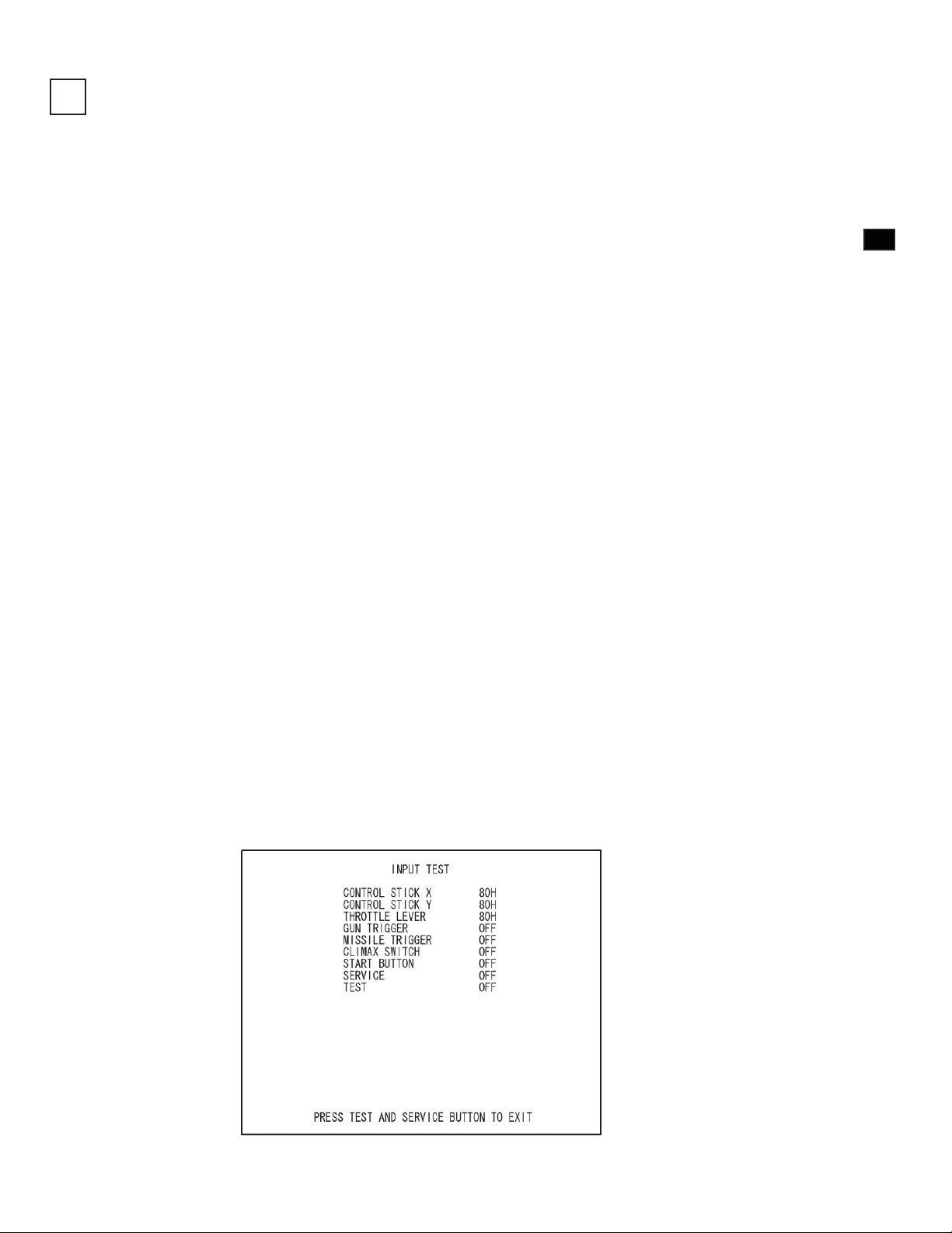
(5) Input Test
When “INPUT TEST” has been selected on the game test mode menu, the screen for testing input device appears. Test
operate the input device by pressing each switch. If the display on the side of each input device changes to “ON” and
numerical values change smoothly in accordance with each operation, the input device and its wiring connections are
normal.
FIG. 6-5a Input Test Screen
17
Page 24
6
ASSEMBL Y AND INST ALLATION
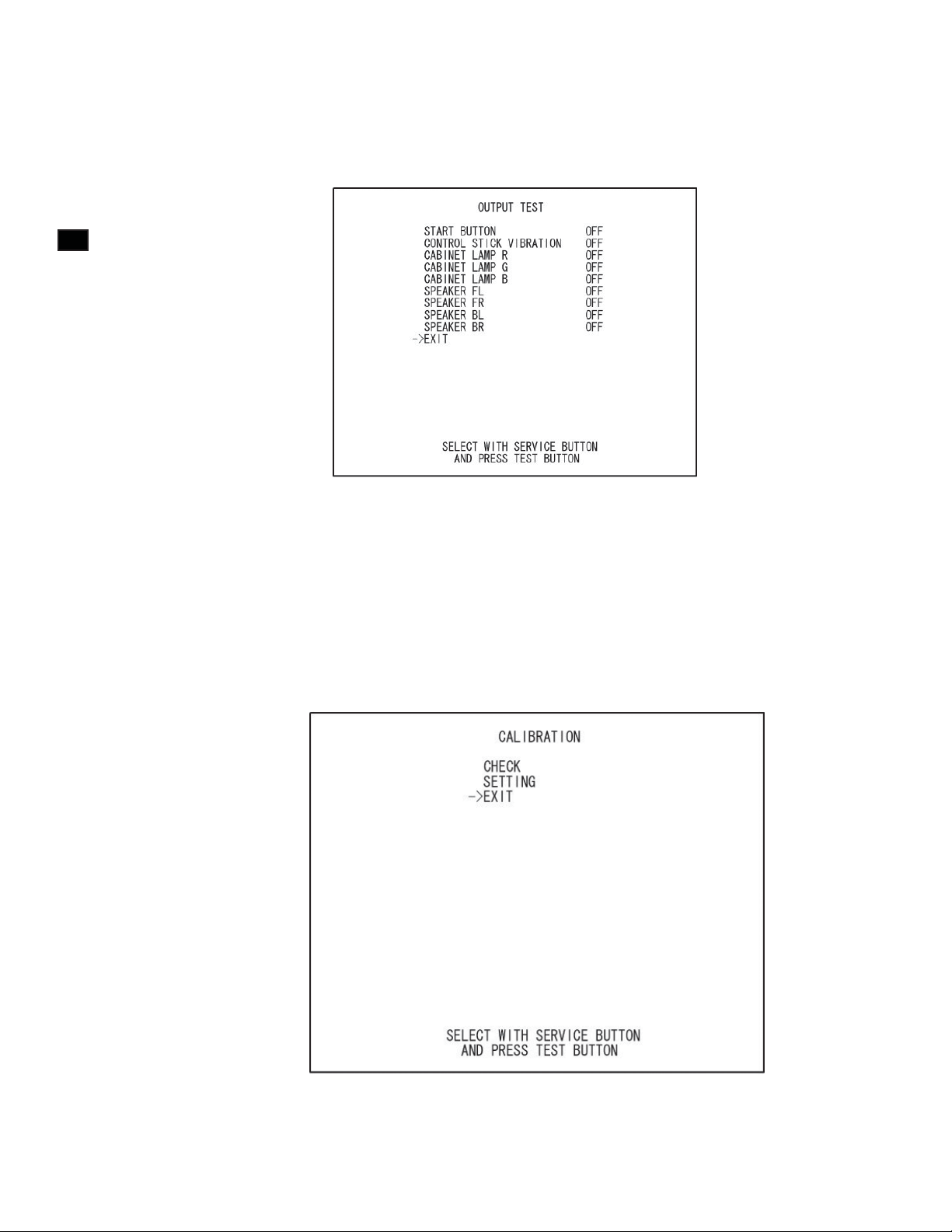
(6) Output Test
When “OUTPUT TEST” has been selected on the game test mode menu, the screen for testing lamps and other output
devices appears.
If each output device operates properly, the output device and its wiring connections are normal.
FIG. 6-5b Output Test Screen
(7) Calibration
Confi rm that the operability of input devices and seat motions during game play do not present any hindrances to play.
Calibration is adjusted when the product is shipped from the factory but it might need to be adjusted again because of
vibrations during transport, etc.
If such things as operability are not satisfactory, select “CALIBRATION” on the game test mode menu and check and
adjust settings.
18
FIG. 6-5c Calibration Menu
Conduct the aforesaid tests when performing routine tests each month.
Page 25
PRECAUTIONS WHEN MOVING THE MACHINE
7
• Always disconnect the power cable before moving the product. If it is moved
with the power cable connected, the cable could be damaged, causing fi re or
electric shock.
• To move the unit over the fl oor, pull in the adjustors and have the casters contact
the fl oor. While moving the unit, be careful that the casters do not roll over the
power cord or the ground wire. If cord or wire is damaged, there could be
electrical shocks and/or short circuits.
• To lift up the cabinet, hold it at the bottom. If you hold it anywhere else, the
weight of the cabinet could cause damage to parts or attachments, resulting in
injury.
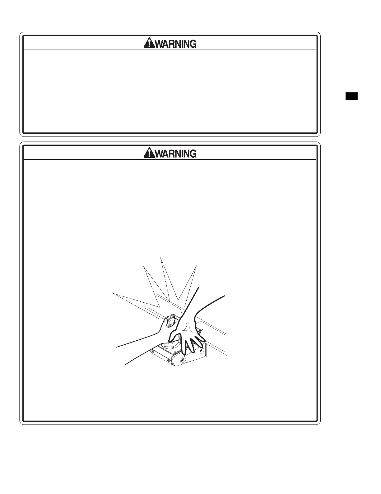
Do not hold or press the plastic parts as indicated by the figure. Failure to observe
this instruction may break the parts, and eventually the broken pieces may cause a
personal injury.
7
PRECAUTIONS WHEN MOVING THE MACHINE AND
7-1 MOVING THE MACHINE
• Observe the following precautions when moving the machine. Failure to observe
these precautions may result in damage to the casters and/or the fl ooring.
- The machine should be moved along a level fl oor.
- Ramps should be used to climb/descend steps 0.400” or greater in height.
- The machine should not be moved any faster than walking speed (about 1.243
MPH).
- The machine should not be tilted too far to one side or loaded excessively on
one side only.
19
Page 26
7
PRECAUTIONS WHEN MOVING THE MACHINE AND
Precautions in Moving Loads
• This product weighs over 550 lbs. It cannot be lifted by human strength alone.
Trying to do so could cause accidents. Use a crane or other powered hauling unit
to move the product.
• When moving a load, insert buffer material between the base and the platform
wall and attach the product securely to the platform with rope or other means. If
exterior parts are damaged or deformed, there could be electrical shocks and/or
short circuits.
• A minimum of 2 or 3 persons is needed to load this machine onto a forklift truck.
The procedure cannot be carried out safely with fewer than this number.
• The forklift should have a platform of at least 60” in length. The procedure cannot
be carried out safely with a platform shorter than this.
• When using a crane to move this machine, ensure that the person operating the
crane is properly qualified. Do not attempt to carry out this procedure without
properly qualifi ed personnel.
• Do not push or support the monitor, control stick, throttle lever or plastic
components while moving or loading the product. Otherwise these components
could be damaged, resulting in injuries from fragments, cracks, etc.
• When transporting the unit by truck, etc., do not secure it with rope, etc., in any
position other than as illustrated. Otherwise components could be damaged,
resulting in injuries from fragments, cracks, etc. Also protect amply with cloth, etc.,
those areas contacted by rope, etc.
• When placing the machine onto a platform or onto the ground, lower it slowly in an
upright, level position. If the machine is lowered at an angle, the weight may be
distributed unevenly and damage to casters/adjusters may result.
20
• Do not have adjustors contact the fl oor on the platform. Otherwise they could be
damaged or deformed by tilts or vibrations during transport.
• Make sure that the product will not undergo violent oscillations. Lay out a vibrationproof mat, for instance, and place the product on top of it.
Page 27
GAME DESCRIPTION
8
The following explanations apply when the product is functioning satisfactorily. Should there be any actions different
from the following contents, some sort of faults may have occurred. Immediately look into the cause of the fault and
eliminate the cause thereof to ensure satisfactory operation.
Normally, when the power is on, the fl uorescent lamp in the billboard on the monitor and the two fl uorescent lamps on
the seat rear surface are lit up. In Attract Mode, such things as game content and rankings are shown on the Attract Mode
Demonstration screen on the monitor.
The colors emitted by the LEDs on the billboard right and left vary depending on the screen content.
Audio output comes from the speakers at the left and right of the monitor and the left and right of the seat backrest.
Presence or absence of audio output in the Attract Mode can be selected by means of the settings in the test mode.
The START button on the control panel is an illuminated button. In Attract Mode, this button is not lit up.
If there are enough credits to enable play, the START button fl ashes. When it is pressed and the game is started, the
START button light goes out.
After the game is over, if there are enough credits to enable play, the START button fl ashes.
The colors emitted by the LEDs on the billboard right and left vary depending on conditions.
LED
BILLBOARD FLUORESCENT LAMP
MONITOR, 29"SANWA
SPEAKERS (At left and right of monitor)
8
GAME DESCRIPTION
CONTROL STICK
FIG. 8a
21
Page 28
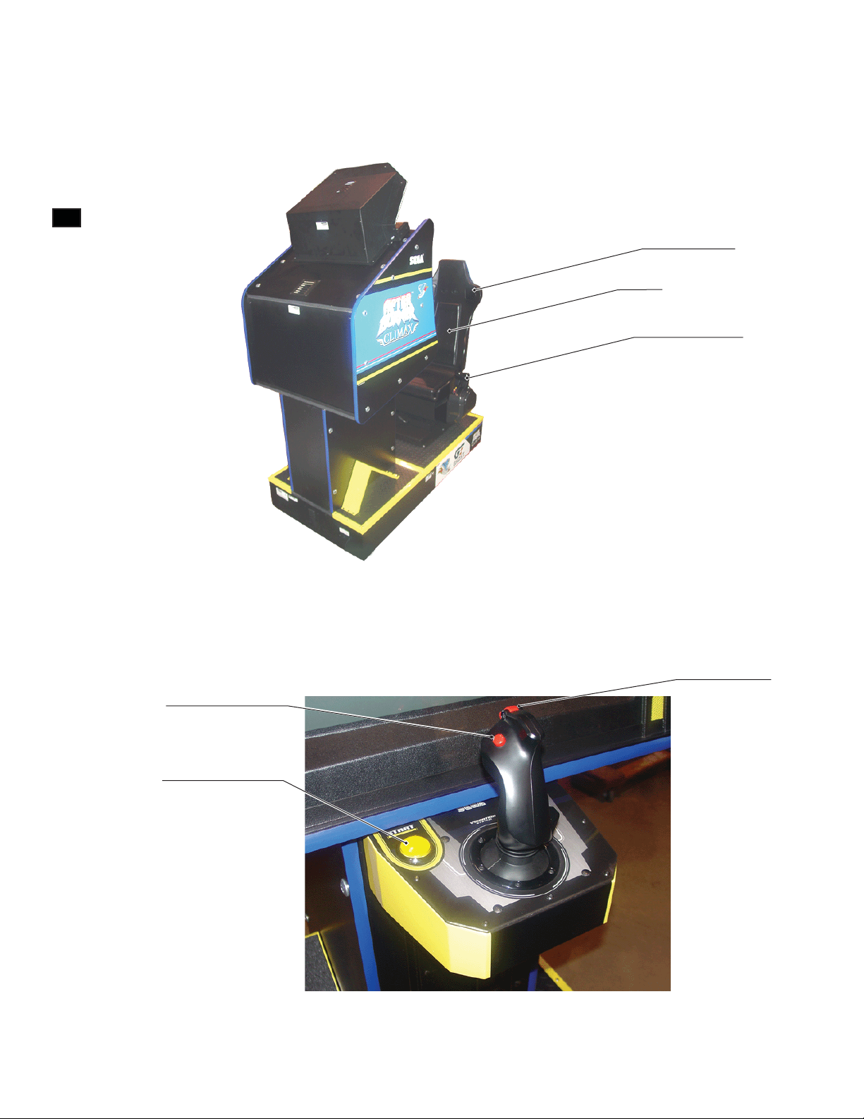
8
GAME DESCRIPTION
REAR SPEAKER
(Left & Right)
SEAT
THROTTLE LEVER
FIG. 8b
22
GUN TRIGGER
MISSILE TRIGGER
START BUTTON
FIG. 8c
Page 29

Game Outline
- AFTER BURNER CLIMAX is a fl ight shooting game that features exhilarating gameplay.
- The player takes on the role of the leader of the “Brave Fangs”, a special air-force unit whose mission is to prevent
the outbreak of all-out nuclear war.
- Fighting the enemy, you proceed through the game’s stages. Attack targets include jet fi ghters, bombers, helicopters,
missile launch sites and facilities.
- Using CLIMAX Mode, a special form of attack style, it is possible to take down large groups of enemies at once.
Attract Mode
The Attract Mode cycles through the following screens.
1. Logo Display
2. Title Screen
3. Movie
4. Title Screen
5. Ranking
6. Title Screen
7. Controls
8. Title Screen
9. Demonstration
10. Return to 1
8
GAME DESCRIPTION
Insert a coin and press the START button during the Attract Mode and the game will start.
However, during FREE PLAY no coins need to be inserted.
Pull the trigger during the Attract Mode and it will skip to the next screen. (The Logo Display cannot be skipped).
23
Page 30
Game Mode Select (Network Play only)
Move the control stick left/right to select a game mode.
1
Pull the trigger or press the START button to confi rm
8
2
GAME DESCRIPTION
ONE-PLAYER Mode:
Play for one player.
selection.
TWO-PLAYER Mode:
Two players play at the same time. Co-operate or compete to clear all stages. At each stage, scores are compared and the
winner/loser is displayed.
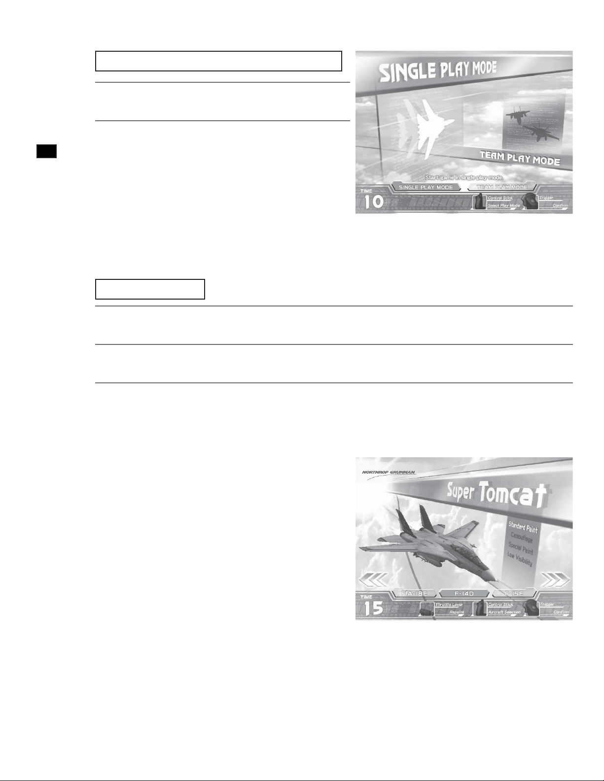
Aircraft Select
Move the control stick left/right to select an aircraft.
FIG. 8e MODE SELECT Screen
1
Push the throttle lever forward or back to change the aircraft paint pattern.
2
Pull the trigger or press the START button to confi rm selection.
3
The three following aircraft can be selected.
- F-14D Super Tomcat
- F-15E Strike Eagle
- F/A-18E Super Hornet
The four following paint patterns can also be selected.
- Standard Paint
- Camoufl age
- Special Paint
- Low Visibility
24
FIG. 8f AIRCRAFT SELECT Screen
Page 31

Stage Composition
FIG. 8g Stage Composition
8
GAME DESCRIPTION
There are a total of 21 stages.
- There are 17 basic stages (shown in squares on the above diagram)
- There are 2 secret stages (stages 06S and 10S on the above diagram)
- There are 2 extra stages (stages 14 and 15 on the above diagram)
Some stages simply have a number, like “01”, and some also have a letter included, like “04A”.
- The numbers on the above diagram denote stage number.
- Where the route splits, an “A” or “B” follows the stage number.
- Secret stages have an “S” following the number.
There are a number of routes that can be taken to the end of the game.
- In some cases the player can choose their route, and in some cases their play will automatically decide which route is
taken.
- The dotted lines on the above diagram denote a route that is automatically determined by play.
- The “No. of Stars earned” effects progress to secret stages.
- The “No. of Critical Commands completed” effects progress to the extra stages.
There are 3 endings.
- There is ENDING A, ENDING B and ENDING C, with ENDING A being the best.
- There are 15 stages to reach ENDING A and ENDING B.
- There are 13 stages to reach ENDING C.
25
Page 32

Controls
8
GAME DESCRIPTION
FIG. 8h Throttle Lever FIG. 8i Control Stick
The player aircraft is controlled by the “Throttle Lever” and “Control Stick”.
<Throttle Lever>
Used to change the speed of the player aircraft.
Pull the lever towards you to decrease speed. Push the lever away from you to increase speed.
Push the lever all the way away from you to activate CLIMAX Mode. CLIMAX Mode requires a full Climax
Gauge to activate.
<Control Stick>
Alters the movement direction of the player aircraft.
Move right to move to the right. Move left to move to the left.
Pull towards you to ascend. Push away from you to descend.
The gun trigger fi res guns, and the missile trigger fi res missiles.
Game Explanation
26
FIG. 8j GAME SCREEN Explanation
Page 33

<Game Rules>
Either clearing all the stages, or all the player aircraft being lost results in Game Over.
All the player aircraft have been lost when there are no remaining player aircraft and the armor gauge falls to 0%.
When an aircraft’s armor gauge falls to 0%, that aircraft is lost, and the remaining player aircraft are reduced by one.
During game play, there are no increases in the number of aircraft and no restoration of the armor gauge.
The number of aircraft at the start of the game is set in test mode.
<Screen Explanation>
- SCORE: Current score.
- COMBO: Current combo. Defeating enemies in quick succession results in a combo.
- MISSILE:
- CLIMAX GAUGE: Once this gauge is fi lled, CLIMAX Mode can be activated.
- SPEED GAUGE: The speed of the player aircraft.
- STAGE: Current stage number.
- STAR:
- LOCK-ON CURSOR: Align this cursor with an enemy to lock-on.
- PLAYER’S AIRCRAFT:
- ARMOR: When the gauge falls to 0% a player aircraft is lost.
- CRITICAL COMMAND: Displays a Critical Command in progress.
<Lock-On>
Remaining number of missiles. Required to fire missiles. They are gradually
replenished.
Current number of stars. Defeating many enemies without taking any damage
earns stars.
When there are no remaining aircraft and the armor gauge falls to 0% it is Game
Over.
8
GAME DESCRIPTION
FIG. 8k Locking On
27
Page 34

Using missiles is the most basic method of attack. A missile may still miss a locked on enemy if your timing is off.
Align the lock-on cursor with an enemy to lock-on to them.
1
Fire a missile while locked on and it will home in on the enemy.
2
8
GAME DESCRIPTION
<After Burners>
When the throttle lever is moved to FAST (far away from you), the after burners ignite and maximum acceleration can
be realized.
The after burners can only be used for a limited period of time.
You must then return your speed to normal for a while before the after burners can be fi red again.
Moving the throttle from SLOW to FAST will allow the after burners to be fi red again more quickly than normal.
<Rolling>
Rolling is a technique for avoiding missiles. Normally, missiles can be avoided by other actions. Rolling is performed as
follows.
Move the control stick left or right for a short time. Move it momentarily all the way to the other side and the
1
<CLIMAX Mode>
aircraft will roll
28
FIG. 8l Activating CLIMAX Mode
FIG. 8m CLIMAX MODE ACTIVATION Screen
Page 35

Using CLIMAX Mode allows a larger number of enemies to be locked on to and taken out at once.
During CLIMAX Mode the lock-on cursor expands, providing more opportunities to attack. You can now quickly lock
onto multiple enemies. During CLIMAX Mode, the number of remaining missile shots is unlimited.
In CLIMAX Mode, motion can begin by pushing the throttle lever all the way to CLIMAX position, the farthest point
away from you.
The Climax Gauge must also be full before CLIMAX Mode will activate. Keeping the throttle lever pushed all the way
from you will keep CLIMAX Mode active.
CLIMAX Mode ends under the following circumstances.
- If the throttle lever is moved out of the CLIMAX position.
- If the Climax Gauge becomes totally empty.
- If damage can be taken during CLIMAX Mode.
[CLIMAX Mode Hints]
* Defeating enemies quickly is vital. The less you use the gauge up, the more often CLIMAX Mode can be used.
* An infi nite number of missiles can be used during CLIMAX Mode, presenting an opportunity to attack even if the
number of remaining missiles are low.
* A Combo increases simply by locking on and fi ring a missile.
<TWO-PLAYER Mode>
8
GAME DESCRIPTION
FIG. 8n TWO-PLAYER Mode GAME Screen
<Game Rules>
Two players compete at the same time to get the higher score. It is also possible to co-operate to clear the stages.
The conditions for Game Over are the same as for the one-player game.
<Evaluation>
Results (WIN/LOSE/DRAW) are determined by comparing the score earned in each stage.
MID-GAME RESULT and TOTAL RESULT display the total score comparison up until that point.
29
Page 36

<Screen Explanation>
- RIVAL: Position and direction of your rival.
- RIVAL’S STATUS: An icon that displays your rival’s current status.
- DOWNED: Displayed when either player is shot down.
8
GAME DESCRIPTION
- PLAYER NUMBER: Player number.
Route Select
Displayed on the right on the Player 01 screen and the left on the Player 02 screen.
(Icons are: CLIMAX Mode, Down, Game Over)
(In red: Player 01 downed; In blue: Player 02 downed)
FIG. 8o ROUTE SELECT Screen
Move the control stick left/right to move the cursor.
1
Pull the gun trigger to select the route.
2
Select the route you wish to take on the ROUTE SELECT screen. The countdown appears in the middle of the screen. If
the time runs out then the route that the cursor is currently highlighting shall be selected.
30
Page 37

CONTINUE Screen
FIG. 8p CONTINUE Screen
On the CONTINUE screen, select whether to continue the game or quit. The countdown appears in the middle of the
screen. If the time runs out, NO will be automatically selected.
8
GAME DESCRIPTION
To continue the game, perform the following before the countdown reaches 0.
<Credit Remains>
If enough credits remain to continue the game, the CONTINUE screen appears and the START button flashes. The
START button is used to select YES when there are enough credits to continue. It is also used to select YES when FREE
PLAY has been set. At any other time the START button has no effect.
Move the control stick left/right to move the cursor.
1
Pull the gun trigger or press the START button to select.
2
<No Credit>
Insert coins. When a coin is inserted the count down resets to 9. When enough coins have been inserted to
1
continue, the START button fl ashes.
Tilt the control stick left/right and move the cursor to YES.
2
3
Pull the gun trigger or press the START button to select.
31
Page 38

Name Entry
If stage 13A, 13B or stage 15 are cleared, and the score is in the top 20 then you can enter your name.
8
GAME DESCRIPTION
A maximum of three characters can be entered.
Name entry ends when END is selected or when time runs out.
Move the control stick left/right to move the cursor. Pull the trigger to select the letter the cursor is aligned to.
1
FIG. 8q NAME ENTRY Screen
Pull the throttle lever towards you to move the cursor to the DEL position. Press the START button to confi rm
2
If name entry ends without anything being input, the name will appear as “???”
If prohibited characters are included in the name, it will automatically be changed to “- - -”
the entered name.
Other Notes
<Change BGM>
On the “PLEASE WAIT” screen displayed after selecting an aircraft, leave the throttle in SLOW and pull the missile
trigger to change the music to the After Burner II BGM.
<Aircraft licenses>
The rights to use all of the aircraft that appear in the game have been obtained from the appropriate licensers.
© SEGA Corporation, 2006
32
Produced under license from Boeing Management Company. Boeing, McDonnell Douglas, McDonnell,
Douglas, North American Aviation, their distinctive airplane liveries, logos and product markings are among the
trademarks owned by Boeing.
Produced under a license from Northrop Grumman Systems Corporation. F-14D Super Tomcat, F-5E Tiger II,
A-10A Thunderbolt II, B-2A Spirit, and CVN-65 Enterprise are trademarks of Northrop Grumman Systems
Corp. and are used under a license to Sega Corporation.
Page 39

EXPLANATION OF TEST AND DATA DISPLAY
9
• Do not touch any parts that are not specified in these directions. Touching
unspecifi ed locations may lead to electric shock or cause short circuits.
• Because of the position of the switch unit, you must assume an unnatural posture to
operate in test mode, which can cause pain in the shoulder, waist, etc. You could
also get caught by parts in the coin chute door, for instance, and suffer abrasions.
Have a fl ashlight on hand and operate in test mode very carefully. The door interior
is dark and narrow and you could easily make mistakes in operation.
• Be careful that a finger or hand does not get caught when opening/closing the
coin chute door.
9
EXPLANATION OF TEST AND DATA DISPLAY
• When you enter the Test Mode, fractional coin and bonus adder data is erased.
• Adjust the sound to the optimum volume, taking into consideration the
environmental requirements of the installation location.
• Removing the Coin Meter circuitry renders the game inoperable.
33
Page 40

9-1 SWITCH UNIT AND COIN METER
Switch Unit
In test mode, the switch unit in the coin chute door is operated.
9
EXPLANATION OF TEST AND DATA DISPLAY
Unlock and open the coin chute door. Inside is a switch unit. There is a monitor adjustment panel at the bottom.
(See Chapter 10.)
COIN METER 2 (OPTION)
TEST SW
COIN METER 1
FIG. 9-1a Coin Meter
TEST Switch (TEST)
Establishes test mode. Becomes the button to confi rm selections in test mode.
REAR SPEAKERS VOLUME
SERVICE SW
FRONT SPEAKERS VOLUME
34
SERVICE Switch (SERVICE)
Makes it possible to enter credits for service without increasing the coin meter. Becomes the button to select items in
test mode.
Front Speaker Volume (FRONT SP.VOL)
This is the volume knob for speakers at the left and right of the monitor. Turn the knob to the right to increase speaker
volume.
Rear Speaker Volume (REAR SP.VOL)
This is the volume knob for speakers at the left and right of the seat backrest. Turn the knob to the right to increase
speaker volume.
Coin Meter
After using a Coin Door key to unlock it, the coin meter can be found inside. (Coin Meter 2 which located in Left is
option.)
Page 41

9-2 SYSTEM TEST MODE
• The details of changes to test mode settings are saved when you exit from test
mode by selecting EXIT from the system test mode menu. Be careful because if the
power is turned off before that point, changes to the settings will be lost.
• Use with the specified settings. If settings other than those specified are used,
inappropriate operations or malfunction may occur.
In the system test mode, the main activities include checking LINDBERGH information and actions and the setting of
coin/credit. Also, a screen appears for checking screen adjustments. For details, see the LINDBERGH service manual,
which is provided separately.
Use the following settings with this product. If the settings are not as specified, error messages might appear and
operations might not be normal.
COIN ASSIGNMENTS
COIN CHUTE TYPE: COMMON
SERVICE TYPE: COMMON
NETWORK SETTING
NETWORK TYPE: MAIN
MAIN NETWORK: SETTING NOT REQUIRED
9
EXPLANATION OF TEST AND DATA DISPLAY
1
2
3
4
When the TEST Button is pressed, the system test mode menu screen (SYSTEM TEST MENU) appears.
Use the SERVICE Button to move the cursor to the desired test item.
Press the TEST Button to confi rm selection of the item.
When testing and checking are completed, select EXIT and press the TEST Button. The SYSTEM TEST MENU
screen reappears.
When all tests are completed, select EXIT and press the TEST Button. The game screen reappears.
SYSTEM TEST MENU
SYSTEM INFORMATION
STORAGE INFORMATION
JVS TEST
MONITOR TEST
SPEAKER TEST
COIN ASSIGNMENTS
CLOCK SETTING
NETWORK SETTING
GAME TEST MODE
-> EXIT
SELECT WITH SERVICE AND PRESS TEST
FIG. 9-2 SYSTEM TEST MENU Screen
35
Page 42

9-3 GAME TEST MODE
9
EXPLANATION OF TEST AND DATA DISPLAY
To change settings in the game test mode, simply making changes on the setting
screen will not be effective. Complete the test mode in normal fashion.
Highlight GAME TEST Mode on the system test mode menu, and press the TEST Button to enter the game test mode.
Once you enter the game test mode, the game test menu will be displayed.
The items displayed on each test screen vary depending on the setting of CABINET TYPE on the game setting screen in
game test mode.
36
FIG. 9-3 GAME TEST MENU Screen
Page 43

1
2
Press the SERVICE Button to highlight the desired menu item with the cursor.
Press the TEST Button to perform the selected item. To learn how to proceed after executing the selected item,
read the item’s explanation. You can also use the control stick and gun trigger to make selections in game test
mode.
When test or setting is completed, take steps to have the game test mode menu screen reappear. The steps
3
4
<Item Explanation>
involved vary with the item.
Select EXIT and press the TEST Button. The system test mode menu screen reappears.
On the system test mode menu screen, select EXIT and press the TEST Button. The game screen reappears
a. INPUT TEST: Perform an input test.
b. OUTPUT TEST: Perform an output test.
c. GAME ASSIGNMENTS: Set up game settings.
d. NETWORK SETTING: Set up network settings.
e. CALIBRATION: Perform calibration.
f. BOOKKEEPING: View bookkeeping records.
g. BACKUP DATA CLEAR: Clear data.
h. EXIT: Return to system test mode menu.
9
EXPLANATION OF TEST AND DATA DISPLAY
a. INPUT TEST
FIG. 9-3a INPUT TEST Screen (CABINET TYPE: STANDARD)
37
Page 44

The condition of each input device can be checked. Periodically check the condition of each input device on this screen.
The number of items displayed varies depending on the setting of CABINET TYPE.
<Operation>
Manipulate the control stick or throttle lever and confirm that the input value on the right side of the item
1
changes smoothly in response to manipulation.
9
EXPLANATION OF TEST AND DATA DISPLAY
2
3
<Menu Explanation>
CONTROL STICK X: Control stick left/right input value
CONTROL STICK Y: Control stick up/down input value
THROTTLE LEVER: Throttle lever front/back input value
GUN TRIGGER: Gun trigger
Manipulate the triggers and buttons and check the display on the right side of the item. The display is normal if
it shows ON when trigger or button is pressed and OFF when trigger or button is released.
When the SERVICE Button and TEST Button are pressed simultaneously, the game test mode menu screen
reappears.
MISSILE TRIGGER: Missile trigger
CLIMAX SWITCH: ON when throttle lever is pressed to monitor side; OFF when lever is released
START BUTTON: START button
SERVICE: SERVICE Button
TEST: TEST Button
b. OUTPUT TEST
38
FIG. 9-3b OUTPUT TEST Screen (CABINET TYPE: STANDARD)
Page 45

The condition of each output device can be checked. Periodically check the condition of each output device on this
screen. Conditions are normal if each device operates and yields output as indicated below.
The number of items displayed varies depending on the setting of CABINET TYPE. For safety, in performing tests in
which the seat moves, manipulate the control stick and gun trigger without standing on the base.
<Operation>
Press the SERVICE Button and move the cursor to the item (output device) you want to test.
1
While the TEST Button is depressed, the display on the right side of the item goes from OFF to ON and the
2
selected output device operates. Confi rm that the device operates normally. If the speakers are operating, you
will hear a buzz-like noise.
Press the SERVICE Button and move the cursor to EXIT.
3
When the TEST Button is pressed, the game test mode menu screen reappears.
4
<Menu Explanation>
START BUTTON: START button lights up at ON; extinguishes at OFF.
CONTROL STICK VIBRATION: Control stick vibrates at ON; stops at OFF.
CABINET LAMP R: LED glows red at ON; extinguishes at OFF.
CABINET LAMP G: LED glows green at ON; extinguishes at OFF.
9
EXPLANATION OF TEST AND DATA DISPLAY
CABINET LAMP B: LED glows blue at ON; extinguishes at OFF.
SPEAKER FL: Monitor left side speaker produces sound at ON; no sound at OFF.
SPEAKER FR: Monitor right side speaker produces sound at ON; no sound at OFF.
SPEAKER BL: Backrest left speaker produces sound at ON; no sound at OFF.
SPEAKER BR: Backrest right speaker produces sound at ON; no sound at OFF.
EXIT: GAME TEST MENU screen reappears.
When AUDIO OUTPUT on the game setting screen is set to “2CH”, speaker-related items change as follows. At “2CH”,
sound is output only from the left and right monitor speakers.
SPEAKER FL: Monitor left speaker produces sound at ON; no sound at OFF.
SPEAKER FR: Monitor right speaker produces sound at ON; no sound at OFF.
39
Page 46

c. GAME ASSIGNMENTS
When the store is crowded inside and motions might be dangerous to customers
passing near the product, set the cabinet so it will not move, then operate the
9
EXPLANATION OF TEST AND DATA DISPLAY
product.
• Setting changes do not become effective until EXIT is selected on the setting
screen. After a setting has been changed, be sure to always exit the setting screen.
• Use this product with the CABINET TYPE set at STANDARD. Otherwise there could be
erroneous operations.
40
FIG. 9-3c GAME ASSIGNMENTS Screen (CABINET TYPE: STANDARD)
Page 47

The various game settings are established. The number of menu items differs depending on the CABINET TYPE setting
in game assignments.
<Operation>
Press the SERVICE Button, move the cursor to the item whose setting is to be changed and select the item.
1
When the TEST Button is pressed, the preset value of the selected item changes. When AUDIO OUTPUT is set
2
3
<Menu Explanation>
DIFFICULTY: Set the Game Difficulty (VERY EASY/EASY/NORMAL/HARD/VERY
PLAYERS AIRCRAFT: Set the number of player aircraft at the start of the game (1 - 9).
CABINET TYPE: Set the cabinet type (DELUXE/STANDARD).
CABINET MOVEMENT: Turn Cabinet Movement ON/OFF.
CONTROL STICK VIBRATION: Turn control stick vibration ON/OFF.
ADVERTISE SOUND: Turn sound during Attract Mode ON/OFF.
AUDIO OUTPUT: Set the speaker output (4CH/2CH).
EXIT: Return to the game test menu screen.
d. NETWORK SETTING
to “2CH”, sound is output only from the monitor right and left speakers.
Press the SERVICE Button and move the cursor to EXIT. When the TEST Button is pressed, the game setting
screen exits and the game test mode menu screen reappears.
HARD).
9
EXPLANATION OF TEST AND DATA DISPLAY
• Network play cannot be implemented without proper setting for network play.
Instead, an error message may be displayed.
• Setting changes do not become effective until EXIT is selected on the setting
screen. After a setting has been changed, be sure to always exit the setting screen.
FIG. 9-3d01 NETWORK SETTING Screen (LINK NUM: 1)
FIG. 9-3d02 NETWORK SETTING Screen (LINK NUM: 2)
41
Page 48

To setup network play with this product, connect two game machines with a network cable.
Change to the settings for network play by proceeding as follows. The number of menu items differs depending on the
LINK NUM setting.
<Operation>
9
EXPLANATION OF TEST AND DATA DISPLAY
1
2
Press the SERVICE button, move the cursor to LINK NUM and select it.
When the TEST button is pressed, the value set for LINK NUM changes. Set each of the two game machines to
“2”. LINK ID is displayed.
Press the SERVICE button, move the cursor to LINK ID and select it.
3
When the TEST button is pressed, the value set for LINK ID changes. Set this value to “1” for one machine and
4
to “2” for the other machine.
Press the SERVICE button and move the cursor to EXIT.
5
When the TEST button is pressed, the network play setting screen exits and the game test mode menu screen
6
<Menu Explanation>
LINK NUM: Set the number of cabinets to link (1 or 2).
LINK ID: Numbers for game machine network play (1/2).
NOTES:
EXIT: Return to the game test menu screen.
reappears.
- Make sure that the two cabinets being used are both given different numbers. If the same number if used
for both, then two-player play will not be possible.
- It is recommended that, facing the screens, the cabinet on the left is given number 1 and the cabinet on
the right is given number 2.
42
NOTE:
After Burner Climax games able 2 cabinets LINK PLAY.
You need 1 LINK (LAN) cable. You need create hole for LINK cable
bottom wood of both base cabinets then thru LINK CABLE there.
(Please refer Chapter 20)
NETWORK (LAN) CABLE (OPTION)
600-7269-0300 (1)
Page 49

e. CALIBRATION
• Change will not be effective simply by making a change on the calibration screen.
When a setting has been changed, be sure to always exit the test mode.
• Calibration is relevant to operability. Manipulate and adjust the input device with
appropriate force. Do not make adjustments with excessive force.
9
EXPLANATION OF TEST AND DATA DISPLAY
FIG. 9-3e01 CALIBRATION Screen
Adjust the volume input value of the input device. When the volume has been replaced, check and adjust it on this
screen.
<Operation>
Press the SERVICE Button and move the cursor to the item you want to select.
1
When the TEST Button is pressed, the selected item is executed.
2
Perform checks and adjustments.
3
The calibration screen reappears.
4
When an adjustment has been made, select CHECK and, on the calibration check screen, make sure that the
adjustment is appropriate.
Press the SERVICE Button and move the cursor to EXIT.
5
6
When the TEST Button is pressed, the calibration screen exits and the game test mode menu screen reappears.
43
Page 50

<Menu Explanation>
CHECK: Proceed to the calibration check screen.
SETTING: Proceed to the calibration screen.
EXIT: Return to the game test menu screen.
9
EXPLANATION OF TEST AND DATA DISPLAY
Calibration Check Screen
FIG. 9-3e02 CALIBRATION Check Screen
<Operation>
Operate the input device whose input value is to be checked.
1
When the TEST Button is pressed, the calibration screen reappears.
2
<Menu Explanation>
CONTROL STICK X: When minimum and maximum values have been input, MIN and MAX are displayed at
the <※1> position, depending on the input. If both MIN and MAX are not displayed
then the game cannot be played properly.
CONTROL STICK Y: When minimum and maximum values have been input, MIN and MAX are displayed at
the <※2> position, depending on the input. If both MIN and MAX are not displayed
then the game cannot be played properly.
44
THROTTLE LEVER: When minimum, maximum, and CLIMAX values have been input, MIN, MAX, and
CLIMAX are displayed at the <※3> position, depending on the input. If MIN, MAX
and CLIMAX are not displayed then the game cannot be played properly.
Page 51

Calibration Select Screen
Shown below is the recommended range in the value for the center position of each
volume. Attach volume so that its value is within this range. [Throttle lever: 80H ± 4H,
Seat: 80H ± 4H]
9
EXPLANATION OF TEST AND DATA DISPLAY
<Operation>
Press the SERVICE Button and move the cursor to the item you want to select.
1
When the TEST Button is pressed, the calibration screen for the selected item appears.
2
Adjust the input values on the calibration screen. The calibration select screen reappears.
3
The calibration select screen reappears.
4
Press the SERVICE Button and move the cursor to EXIT.
5
When the TEST Button is pressed, the calibration screen reappears.
6
<Menu Explanation>
FIG. 9-3e03 CARIBRATION SELECT Screen
CONTROL STICK: Proceed to the control stick calibration screen.
THROTTLE LEVER: Proceed to the throttle lever calibration screen.
SEAT CENTER POSITION: Proceed to the calibration screen for seat center position.
EXIT: Return to the calibration screen.
45
Page 52

Control Stick Calibration Screen
STEP 1 aligns the center position for the control stick.
1
After determining the center position, proceed to STEP 2.
9
EXPLANATION OF TEST AND DATA DISPLAY
Press the TEST Bbutton after releasing your hand from the control stick.
FIG. 9-3e04 CONTROL STICK (STEP1) Screen
STEP 2 aligns the MIN/MAX positions for the control stick.
2
(After moving it past a certain position, the message “PRESS TEST BUTTON TO EXIT” will be displayed.)
Push the control stick as far as possible in all directions (left/right/forward/back).
46
FIG. 9-3e05 CONTROL STICK (STEP2-1) Screen
Page 53

FIG. 9-3e06 CONTROL STICK (STEP2-2) Screen
Press the TEST Button to set these MIN/MAX settings (left/right/forward/back) and return to the calibration
3
select screen.
Throttle Lever Calibration Screen
PRESS TEST BUTTON TO EXIT” is displayed.
“
9
EXPLANATION OF TEST AND DATA DISPLAY
STEP 1 aligns the center position for the throttle lever.
1
After determining the center position, proceed to STEP 2.
Press the TEST Button after releasing your hand from the throttle lever.
FIG. 9-3e07 THROTTLE LEVER (STEP1) Screen
47
Page 54

STEP 2 aligns the MIN/MAX positions for the throttle lever.
2
If CLIMAX Mode has been entered, once the MIN/MAX position has been determined, repeat the same
After moving it past a certain position, the message “PRESS TEST BUTTON TO EXIT” will be displayed.
Push the throttle lever as far as possible in both directions (forward/back). Make sure that you do not push the
lever into CLIMAX Mode when inputting the MAX value. If you do so the game cannot be played properly.
procedure to amend.
9
EXPLANATION OF TEST AND DATA DISPLAY
FIG. 9-3e08 THROTTLE LEVER (STEP2-1) Screen
FIG. 9-3e09 THROTTLE LEVER (STEP2-2) Screen
48
“PRESS TEST BUTTON TO EXIT” is displayed.
Press the TEST Button to set these MIN/MAX settings and return to the calibration select screen.
3
Page 55

f. BOOKKEEPING
Displays bookkeeping information across 4 screens.
When the TEST Button is pressed, proceed to the next screen. When the TEST Button is pressed while the (4/4) screen is
displayed, the game test mode menu screen reappears.
9
EXPLANATION OF TEST AND DATA DISPLAY
FIG. 9-3f01 BOOKKEEPING Screen (1/4)
<Menu Explanation>
COIN 1: Number of coins inserted into coin chute 1.
COIN 2: Number of coins inserted into coin chute 2.
TOTAL COINS: Total of COIN 1 and COIN 2.
COIN CREDITS: Number of credits awarded from inserting coins.
SERVICE CREDITS: Number of credits awarded with the SERVICE Button.
TOTAL CREDITS: Total of COIN CREDITS and SERVICE CREDITS.
49
Page 56

9
EXPLANATION OF TEST AND DATA DISPLAY
FIG. 9-3f02 BOOKKEEPING Screen (2/4)
<Menu Explanation>
NUMBER OF GAMES: Total number of games played.
TOTAL TIME: Total time that power has been supplied to the cabinet.
(Time power is supplied, except during test mode.)
PLAY TIME: Total play time.
AVERAGE PLAY TIME: Average play time.
LONGEST PLAY TIME: Longest play time.
SHORTEST PLAY TIME: Shortest play time.
50
FIG. 9-3f03 BOOKKEEPING Screen (3/4)
<Menu Explanation>
TIME HISTOGRAM: Total number of plays in each time bracket.
Page 57

FIG. 9-3f04 BOOKKEEPING Screen (4/4)
<Menu Explanation>
NUMBER OF GAMES: Total number of games.
NUMBER OF GAME START: Total number of games started.
NUMBER OF CONTINUE: Total number of continues.
NUMBER OF GAMECLEAR: Total times the game has been cleared.
NUMBER OF GAMEOVER: Total number of Game Overs.
9
EXPLANATION OF TEST AND DATA DISPLAY
AVERAGE NUMBER OF CONTINUE: Average number of continues.
MIN NUMBER OF CONTINUE TO CLEARED: Minimum number of continues until ENDING is reached.
AVERAGE NUMBER OF CONTINUE TO CLEARD: Average number of continues until ENDING is reached.
NUMBER OF TEAM PLAY: Total number of two-player games.
NUMBER OF MID-GAME ENTRY: Total number of mid-game entries, and total number
of mid-game entries plus number of continues after
GAMEOVER.
NUMBER OF MOTION STOP DURING GAME: Number of times the MOTION STOP button has been
pressed.
NUMBER OF SENSOR VIOLATIONS: Number of times a sensor has reacted. (Only counted
when the seat is unlocked.)
51
Page 58

g. BACKUP DATA CLEAR
9
EXPLANATION OF TEST AND DATA DISPLAY
FIG. 9-3g01 BACKUP DATA CLEAR Screen
<Menu Explanation>
CLEAR ALL BACKUP DATA: Clear all data (both ranking and bookkeeping).
CLEAR RANKING DATA(RANK01~20) ONLY: Clear only ranking data.
CLEAR RANKING DATA(RANK11~20) ONLY: Clear only ranking data from (rank 11 to 20 only).
CLEAR BOOKKEEP DATA ONLY: Clear only bookkeeping data.
EXIT: Return to game test menu screen.
After selecting one of the above items the following confi rmation screen will be displayed.
The screen below is displayed when CLEAR ALL BACKUP DATA is selected, but the screen is almost identical in other
cases too.
FIG. 9-3g02 BACKUP DATA CLEAR Screen
If you wish to clear data, press the SERVICE Button to highlight YES and then press the TEST Button.
“COMPLETED” will be displayed once the data has been erased.
When the TEST Button is pressed, the game test mode menu screen reappears.
52
If you don’t wish to clear data, press the SERVICE Button to highlight NO and then press the TEST Button.
Return to BACKUP DATA CLEAR screen.
Page 59

MONITOR
10
10-1
Before handling the monitor, be sure to read the following points and comply with the caution/warning instructions
given below. Note the caution/warning symbols and letters used in the instructions.
• When performing such work as installing and removing the monitor, inserting and
CAUTIONS/WARNINGS REGARDING SAFETY FOR HANDLING THE MONITOR
Indicates that handling the monitors improperly by disregarding this warning may potentially
cause a hazardous situation, which could result in death or serious injury.
Indicates that handling the monitors by disregarding this caution may cause a potentially
hazardous situation, which could result in personal injury and or material damage.
Indicates that access to a specifi c part of the equipment is forbidden.
Indicates the instruction to disconnect or unplug a power connector.
disconnecting the external connectors to and from the monitor interior and the
monitor itself, be sure to disconnect the power connector (plug) beforehand.
Proceeding without doing so can cause electric shock or malfunctioning.
10
MONITOR
• Use of the monitor by converting it without permission is not allowed. SEGA shall not
be liable for any malfunctioning and accidents caused by such a conversion.
• Primary side and Secondary side
The monitor's circuit, which is divided into the Primary side and Secondary side,
is electrically isolated. Do not touch the Primary side, or touch both the Primary
side and the Secondary side simultaneously. Failing to observe this instruction
can cause electric shock, leading to serious danger. When making monitor
adjustments, use a non-conductive driver and make them without touching any
part other than the Adjustment V. R. and knob. Also, be sure not to cause a short
circuit to the Primary side and Secondary side. If a short circuit occurs, it can cause
electric shock or malfunctioning, which poses
a serious risk of danger.
53
Page 60

10
MONITOR
• High Voltage
Some of the parts inside the monitor are subject to high voltage in excess of 20,000
volts and pose a serious threat. Therefore, do not touch the monitor interior. Should
soldering & paper wastes, etc. be mixed in the monitor interior, turn the power off
so as not to cause malfunctioning or a fi re hazard.
• Connecting the CRT and PCB
When combining the CRT and PCB, use the specified part No. to maintain
the factory settings. The anode of the CRT itself will charge as time elapses,
generating high voltage that is very dangerous. The monitor should be used with
the Chassis, CRT, and PCB assembled. When repair, etc. is required at the time
of malfunctioning, be sure to send it in an assembled state. If it is disassembled,
the charged high voltage can be released, causing a very hazardous situation.
Therefore, under no circumstances should it be disassembled.
54
• Static Electricity
Touching the CRT surface sometimes causes a slight shock. This is because the CRT
surfaces are subject to static and will not adversely affect the human body.
• Installation and Removal
Ensure that the Demagnetizer Coil, FBT (Fly-Back Transformer), Anode Lead, and
Focus Lead are not positioned close to the sheet metal work's sharp edges, etc.
and avoid damaging the insulated portions so as not to cause electric shock and
malfunctioning. (For the name of parts, refer to the fi gures above.)
Page 61

Antistatic sheet is used in the product’s CRT to prevent electrifi cation. To protect this
sheet, observe the following precautions. If the sheet is damaged, the customer could
be electrocuted. There are cases in which sheet edges peel off and turn white, but
this poses no problems in usage.
• Do not contact the antistatic sheet on the
CRT surface, or rub it, with a hard implement
(pointed bar or pen, etc.).
• Do not affix stickers or anything else that
might damage the antistatic sheet on the
CRT surface, or cause the sheet to peel off.
• Do not remove aluminum foils from the
CRT corners. Removing the aluminum foils
can cause static prevention effects to be
lowered.
10-2 CLEANING THE CRT SURFACES
10
MONITOR
The antistatic sheet is attached onto the CRT surface. Observe the following
precautions when cleaning. Damage to the antistatic sheet could result in electrical
shock.
• Remove smears by using a dry, soft cloth (flannels, etc.). Do not use a coarse
gauze, etc.
• For smear removing solvent, alcohol (ethanol) is recommended. When using
chemical detergent, be sure to follow instructions below:
- Dilute chemical detergent with water and dip a soft cloth in and then thoroughly
wring it to wipe smears off.
- Do not use a chemical detergent containing an abradant, powder or bleaching
agent.
- Do not use alkaline chemical detergents such as "glass cleaner" available on the
market or solvents such as thinner, etc.
• Do not rub or scratch the CRT face with hard items such as brushes, scrub brush,
etc.
Clean the CRT once a week. Observe the aforesaid precautions in cleaning so as not to damage antistatic sheet on the
CRT surface.
55
Page 62

10
MONITOR
10-3 ADJUSTMENT PROCEDURE
• Monitor adjustments have been made at the time of shipment. Therefore, do not
make further adjustment without a justifi able reason. Adjusting the monitor which
contains high tension parts is dangerous work. Also, an erroneous adjustment can
cause deviated synchronization and image fault, resulting in malfunctioning.
• Be sure to perform appropriate adjustment of the monitor (projector). For
operation of this machine, do not leave monitor's flickering or deviation as is.
Failure to observe this can cause to worsen the players' or the customers' physical
conditions.
• Do not touch undesignated places. Touching places not designated can cause
electric shock or short circuit.
There is a monitor adjustment board at the bottom of the Monitor inside the Front Glass. Remove 4 each out side of
screws to take off Speaker bracket frame, Bezel and Front Glass then you able to access Adjustment board.
FIG. 10-3
ADJUSTMENT BOARD
This product’s monitor is SANWA MONITOR 29E31S-B (SEGA Part#: 998-0162). For adjustment method, carefully
read and carry out the following.
CONT: adjusts image contrast.
Turn potentiometer lockways, it becomes deep and becomes light when turn it counter clockways.
BRIT: adjusts the on-screen image brightness.
Turn potentiometer clockways, it becomes bright and becomes dark with turn it counter clockways.
HSIZ: adjusts the horizontal image size.
Turn potentiometer clockways, it becomes large and becomes small with the DOWN button.
56
HPOS: adjusts the horizontal image's position.
Turn potentiometer clockways, it moves to the left and moves to the right with turn it counter clockways.
VSIZ: adjusts the vertical image size.
Turn potentiometer clockways, it becomes large and becomes small with turn it counter clockwaysn.
VPOS: adjusts the vertical image's position.
Turn potentiometer clockways, it moves upwards and moves downwards with turn it counter clockways.
Page 63

CONTROL STICK
11
• When working with the product, be sure to turn the power off. Working with the
power on may cause an electric shock or short circuit.
• Be careful not to damage the wires. Damaged wires may cause an electric shock,
short circuit or present a risk of fi re.
• Do not touch any parts that are not specified in these directions. Touching
unspecifi ed locations may lead to electric shock or cause short circuits.
• This work should be performed by site maintenance personnel or other skilled
professionals. Work performed by non-technical personnel can cause a severe
accident such as an electric shock.
• To prevent accidents while working or while operating the product after it has been
installed, be sure not to conduct any procedures other than those given in this
manual. There are cases in which procedures not covered in this manual require
special tools and skills. If a procedure not given in this manual is required, request
service from the offi ce given in this manual or from the point of purchase.
11
CONTROL STICK
• Exercise due caution in performing soldering procedures. If soldering iron is
handled carelessly, there could be fi res or burns.
• Proceed very carefully when heating thermal contraction tube. Careless operations
can result in fi res or burns.
• In performing adjustments or replacements, check the surroundings before
powering up. The product undergoes initialization automatically after the power
has been engaged. If someone is near the product and the seat moves left or right,
there could be a collision or fall.
• When fastening plastic parts, be careful not to tighten screws and nuts excessively.
Otherwise parts may be damaged, resulting in injuries from fragments, etc.
• Be careful not to get hand or fi nger caught when opening or closing the controller
lid.
• Control stick connectors are removed within a narrow cabinet. Be careful as there
is the danger of abrasions.
• While holding the control stick fi rmly, remove the 4 fl ange nuts that fasten it. If the
control stick falls on you, you could be injured.
57
Page 64

11
CONTROL STICK
• After the volume has been replaced, be sure to set the volume value on the test
mode calibration screen and the input test screen and check variations in the
volume value.
• After adjusting or replacing a microswitch, always check ON/OFF of the switch on
the input test screen of the test mode.
• Handle parts inside the control stick very carefully. Be especially careful to avoid
damage, deformation or loss of these parts. If any one of these parts is lost or
defective, it can result in damages and/or faulty operations.
If the operability of the control stick is unsatisfactory, or if settings on the test mode calibration screen are ineffective, the
problem could be a defective mechanism, displacement of the position where volume or microswitch has been fastened,
or malfunctioning of volume or microswitch.
Carry out the following procedure to replace control stick or microswitch. Also be sure to grease the mechanical
components of the control stick once every 3 months.
11-1 HOW TO REMOVE CONTROL STICK
To replace the control stick volume or microswitch, remove the control stick. It is very diffi cult to work with the control
stick attached and parts or wiring could be damaged.
The following tools are needed for the following procedure.
- 2.5 mm Allen wrench or screwdriver
- 8 mm spanner, Allen screwdriver or socket wrench
Power OFF the machine.
1
Remove the 6 tamper screws in bottom of the control stick base to open the Bottom cover plate.
2
FIG. 11-1a
After open the Bottom cover plate under
the control stick base.
58
Page 65

Remove the 2 wire connectors on the control stick.
3
At the bottom of the control stick there is a board on the right side as you face the monitor. Off the connectors
4
5
connected to this board, remove the connector on the monitor side.
Remove the 4 nuts that fasten the control stick from the bottom. Hold the control stick fi rmly while proceeding.
Pull the control stick downward to remove it. Be careful not to damage wiring.
11-2 GREASING
• Be sure to use the designated grease. Using undesignated grease can cause parts
damage.
• Do not apply grease to locations other than as specifi ed. Doing so may create a
risk of operational problems and deterioration of parts.
11
CONTROL STICK
• The designated periods for greasing serve only as a guide. Whenever there are
squeaks or other anomalies, apply grease at designated locations.
Once every 3 months, apply grease to the spring and sliding part of the mechanical component that turns the volume
shaft. Use Greasemate (PART NO. 090-0066).
FIG. 11-2
59
Page 66

11-3 VOLUME REPLACEMENT
If control stick operability is unsatisfactory and settings on the test mode calibration screen are ineffective, the problem
could be a malfunction of the control stick volume.
Remove the control stick and replace the volume.
Please note, however, that the control stick has two volumes. Make sure you are replacing the correct volume.
11
CONTROL STICK
Have available a volume for replacement and three thermal contraction tubes (PART NO. 310-5029-D12).
Use the following tools and solder.
- 2.5 mm Allen wrench or screwdriver
- 8 mm spanner, Allen screwdriver or socket wrench
- Philips screwdriver (for M3 screw)
- 11 to 12 mm spanner
- Nippers
- Cutter
- Wire stripper
- Soldering iron
- Industrial drier
Cut off the power and remove the control stick.
1
Take out the 2 screws that hold down the volume bracket.
2
60
X-POT, WIRE COLOR
1: WHITE
2: ORANGE
3: RED
Y-POT, WIRE COLOR
1: RED
2: GREEN
3: WHITE
FIG. 11-3a
Page 67

3
4
Remove the volume together with volume bracket
from the control stick.
11
CONTROL STICK
FIG. 11-3b
Take off the hexagon nut that fastens the volume to
the volume bracket, then remove the volume from the
bracket.
5
6
FIG. 11-3c
Wire connected to the volume can be used as is. Use nippers or cutters to remove old thermal contraction tube
from wire connection sites.
Use a soldering iron to melt soldered joints and remove wire from old volume. Exercise extreme caution in
using the soldering iron.
FIG. 11-3d
61
Page 68

11
CONTROL STICK
7
8
If the length of wire exposed at the wire tip does
not reach 5 mm, use wire stripper or cutter to
remove wire cover.
FIG. 11-3e
Pass one wire through each thermal contraction tube.
FIG. 11-3f
62
9
Solder wire to the pin of the new volume.
Refer to wiring diagram and make sure that you are using soldering wire.
FIG. 11-3g
Page 69

10
11
Heat with industrial dryer and affi x thermal contraction tube so that it covers soldered area.
FIG. 11-3h
11
CONTROL STICK
Attach the volume to the volume bracket, then attach this assembly to the control stick. Align the D-cut surface
of the volume shaft with the D-cut surface of the hole on the side of the control stick, then insert the shaft.
FIG. 11-3i
12
13
14
15
16
Fasten volume bracket with 2 screws.
Attach control stick.
Engage the power. Note that initialization takes place.
Establish volume setting on the game test mode calibration screen. (See 9-3e).
Simply changing settings on the calibration screen will not be effective. Terminate the test mode. Note that
initialization takes place upon termination of the test mode.
63
Page 70

11-4 MICROSWITCH REPLACEMENT
If operability of the gun trigger is unsatisfactory, the problem could be a malfunction of the microswitch inside the
control stick grip.
Remove the control stick and replace the microswitch.
11
CONTROL STICK
Use the following tools, solder and screw lock agent (PART NO. 090-0012).
- 2.5 mm Allen wrench or screwdriver
- 8 mm spanner, Allen screwdriver or socket wrench
- Philips screwdriver (for M4 screw)
- Soldering iron
Cut off the power and remove the control stick. (See
1
2
11-1.)
Press down on the rubber cover at the base of the
control stick grip.
FIG. 11-4a
Take out 3 screws and remove grip R. Be careful when removing the grip that parts inside the grip do not come
3
FIG. 11-4b FIG. 11-4c
out and get lost.
64
Page 71

4
5
6
The grip L microswitch is inserted. Pull out the microswitch slowly so as not to damage wire.
FIG. 11-4d
11
CONTROL STICK
Use a soldering iron to remove wire to be connected by solder to microswitch pin. Solder wire to the
pin of the new microswitch. Insert microswitch into grip L, then attach grip L.
Attach grip R and fasten it with 3 screws, being careful not to let wire get caught anywhere. Coat the
screws with screw lock agent at this time. Also be careful not to tighten the screws excessively
Attach control stick. Engage the power. Note that initialization takes place. Check gun trigger input
7
Among the potential causes of abnormal control stick operability, apart from volume malfunctions, are wear
and/or damage to guide plates. Use the following tools to replace a guide plate.
- 2.5 mm Allen wrench or screwdriver
- 4 mm Allen wrench or screwdriver
1
on the game test mode input test screen.
11-5 GUIDE PLATE REPLACEMENT
Cut off the power and open the controller lid at the bottom of the control stick. Take out 4 hexagon
socket screws that hold down the guide plate, then replace the guide plate.
FIG. 11-5
65
Page 72

12
• When working with the product, be sure to turn the power off. Working with the
12
THROTTLE LEVER
power on may cause an electric shock or short circuit.
• Be careful not to damage the wires. Damaged wires may cause an electric shock,
short circuit or present a risk of fi re.
• Do not touch any parts that are not specified in these directions. Touching
unspecifi ed locations may lead to electric shock or cause short circuits.
• This work should be performed by site maintenance personnel or other skilled
professionals. Work performed by non-technical personnel can cause a severe
accident such as an electric shock.
• Exercise due caution in performing soldering procedures. If soldering iron is
handled carelessly, there could be fi res or burns.
• Proceed very carefully when heating thermal contraction tube. Careless operations
can result in fi res or burns.
• In performing adjustments or replacements, check the surroundings before
powering up. The product undergoes initialization automatically after the power
has been engaged. If someone is near the product and the seat moves left or right,
there could be a collision or fall.
THROTTLE LEVER
66
When fastening plastic parts, be careful not to tighten screws and nuts excessively.
Otherwise parts may be damaged, resulting in injuries from fragments, etc.
After the volume has been replaced, be sure to set the volume value on the test
mode calibration screen and the input test screen and check variations in the volume
value.
If the operability of the throttle lever is unsatisfactory, or if the lever is ineffective with the settings on the test mode
calibration screen, the problem could be faulty gear mesh or volume malfunction.
Grease the mechanical component of the throttle lever once every 3 months.
Page 73

12-1 GREASING
• Be sure to use the designated grease. Using undesignated grease can cause parts
damage.
• Do not apply grease to locations other than as specifi ed. Doing so may create a
risk of operational problems and deterioration of parts.
• The designated periods for greasing serve only as a guide. Whenever there are
squeaks or other anomalies, apply grease at designated locations.
Once every 3 months apply grease to the spring and gear mesh that turn the volume shaft.
Use Greasemate (PART NO. 090-0066).
Cut off the power supply. Remove the 4 truss screws that hold the throttle cover lower. Flat washers are used
1
with the truss screws.
12
THROTTLE LEVER
FIG. 12-1a FIG. 12-1b
Remove throttle cover lower.
2
FIG. 12-1c
67
Page 74

4
12
THROTTLE LEVER
Apply grease only at designated locations. When attaching throttle cover lower, make sure that wires do not get
caught anywhere.
FIG. 12-1d
68
Page 75

12-2 VOLUME ADJUSTMENT OR REPLACEMENT
When the volume that detects throttle lever operation is unsatisfactory, either adjust the gear mesh or replace the volume
by proceeding as follows.
With this product, when the lever has been operated fully to front or rear, if the volume rotary shaft turns within its
movable range, there is no danger that the volume will be damaged. With your hand released from the lever, fasten the
volume so that the gear fi ts properly with the volume shaft in the designated direction.
The following tools are required for the following procedure.
- Philips screwdriver for M4 screw, 2 mm Allen wrench or screwdriver, 11 to 12 mm spanner, Nippers,
Cutter, Soldering iron, Industrial drier
Adjustment Method
Power OFF the machine. Take out the 4 truss screws and remove throttle cover lower. (See 12-1.) Loosen the 2
1
2
screws that hold down the VR bracket.
Adjust the gear mesh so that the volume shaft turns smoothly when the lever is manipulated and so that the
incline of the volume shaft (D cut surface direction) when hand is removed from the lever is as shown in the
illustration.
12
THROTTLE LEVER
FIG. 12-2a
3
4
5
6
FIG. 12-2b
Tighten the 2 loosened screws. Turn on the power. Note that initialization takes place.
Check the volume value on the game test mode input test screen. Confi rm that changes take place smoothly
in accordance with lever operation. Also confi rm that the value when hand has been removed from the lever is
[80H+/-4H].
Align the center position of throttle lever on the calibration screen. (See 9-3e.)
Simply changing the setting on the calibration screen will not be effective. Terminate the test mode. Note that
initialization takes place when the test mode is terminated.
69
Page 76

Replacement Method
Make available the volume for replacement and 3 thermal contraction tubes (PART NO. 310-5029-D20).
1
12
THROTTLE LEVER
2
3
Cut off the power supply.
Take out the 4 truss screws and remove the throttle base cover backet.
Unfasten the 2 cord clamps that hold down wire connected to the volume.
4
FIG. 12-2c
Remove the connector.
70
FIG. 12-2d
Page 77

5
6
Remove the 2 screws that fasten the VR bracket. Flat and spring washers are used with these screws.
12
THROTTLE LEVER
FIG. 12-2e
Remove the volume together with VR bracket. Be careful not to damage the wire connected to the volume.
7
FIG. 12-2f
Loosen the 2 hexagon socket screws that fasten the gear. Withdraw the gear from the volume shaft.
FIG. 12-2g
71
Page 78

8
9
12
THROTTLE LEVER
10
11
12
Remove the nuts that fasten the VR bracket, then remove volume from VR bracket and replace.
The wire connected to the volume is used as is. Take away the thermal contraction tube with nippers or cutter,
melt the soldered areas with a soldering iron and remove wire from the volume.
Cover the soldered areas with thermal contraction tube. In place of the thermal contraction tube that was cut
away, pass each wire through new thermal contraction tube.
Solder the wire to the new volume. Check the wiring diagram to be sure there are no errors in wiring.
Cover the soldered areas with thermal contraction tube. Heat the thermal contraction tube with an industrial
drier so that the tube adheres to soldered areas.
1:BLK
2:GRAY/YEL
13
14
15
3:RED
1
3
FIG. 12-2h Volume Replacement
Attach the gear and VR bracket to volume.
After passing the wire, attach the volume. While your hand is removed from the lever, align gear mesh so that
the D cut surface of the volume shaft is level, facing directly upward, then fasten with 2 screws. (See FIG.
12-2b.)
Manipulate the lever to check that the gear rotates smoothly. Connect the connector and fasten wire with 2 cord
clamps
72
16
17
18
Attach the throttle cover lower. Be careful that the wire does not get caught anywhere. Turn on the power. Note
that initialization takes place
Establish volume settings on the game test mode calibration screen. (See 9-3e.)
Simply changing the settings on calibration screen will not be effective. Terminate the test mode. Note that
initialization takes place when test mode has been terminated.
Page 79

PERIODIC INSPECTION
13
• Once a year, check to see if power cords are damaged, the plug is securely
inserted, dust is accumulated between the socket outlet and the power plug, etc.
Using the product with accumulated dust in the interior may cause fi re or electric
shock.
• Never use a water jet, etc. to clean the inside and outside of the cabinet. If wetness
occurs for any reason, do not use the product until it has completely dried.
• Once a year, request the office shown on this manual or the dealer from whom
the product was originally purchased to perform the internal cleaning. Using the
product with accumulated dust in the interior may cause fi re or other accidents.
Note that you are liable for the cost of cleaning the interior parts.
• Once a year, request the office shown in this manual or the dealer from whom
the product was originally purchased to perform routine maintenance on moving
mechanisms. Failure to perform maintenance can lead to accidents.
• There is the danger of accidents involving electrical shorts circuits or fi re caused
by factors such as the deterioration of insulation in electrical and electronic
equipment over time. Check that there are no abnormalities such as odors from
burning.
13
PEROPDOC ONSPECTION
If there is only enough space for ventilation in the area reserved for product
installation and operation, do not begin maintenance work until space has also been
set aside for maintenance. Such work cannot be performed safely and thoroughly in
narrow spaces.
In order to maintain the performance of this product and operate it safely, inspect the following items routinely and
perform maintenance.
The player directly touches and manipulates the control stick and throttle lever with his/her hands. Clean these
components as necessary and provide hand towels, etc., so that players will be comfortable while playing.
73
Page 80

TABLE 13 PERIODIC INSPECTION TABLE
ITEMS DESCRIPTION PERIOD REFERENCE
CABINET Confirm that adjusters contact
MONITOR Screen cleaning Weekly 10-2
13
PEROPDOC ONSPECTION
CONTROL STICK Inspection of volume, switch 1 month 9-3a
THROTTLE LEVER Inspection of volume, switch 1 month 9-3a
COIN SELECTOR Inspection of coin switch 1 month Service manual,
GAME BOARD Check of board information 1 month Service manual,
Daily 3
fl oor
Check screen adjustment Monthly or
when moving
Greasing 3 months 11-2
Greasing 3 months 12-1
Coin insertion test 1 month Chapter 14
Coin Selector cleaning 3 months Chapter 14
Check of settings 1 month 9-3c, 9-3d
6 7 , 10-3
Chapter 4
Chapter 4
FLUORESCENT LAMP Inspection of lighting fi xtures As appropriate Chapter 15
ELECTRICAL/
ELECTRONIC PARTS
POWER CABLE Inspection, Cleaning 1 year See above.
CABINET INTERIOR Cleaning 1 year See above.
CABINET SURFACES Cleaning As appropriate See below.
MOVING MECHANISMS Maintenance 1 year Previous page
Inspection As appropriate Previous page
Cleaning the Cabinet Surfaces
When the cabinet surfaces become dirty, remove stains with a soft cloth soaked in water or diluted (with water) chemical
detergent and then wrung dry. To avoid damaging the fi nish, do not use such solvents as thinner, benzene, etc. (other than
ethyl alcohol) or abrasives (bleaching agent and chemical dust-cloth).
Some general-purpose household, kitchen, and furniture cleaning products may contain strong solvents that degrade
plastic parts, coatings, and print. Before using any cleaning product, read the product's cautionary notes carefully and
test the product fi rst on a small area that is not highly visible.
74
Page 81

TROUBLESHOOTING
14
• If an error message is displayed, have the problem looked at by a store
maintenance person or a technician. Unless the problem is addressed by
someone with specialized knowledge or skills, there could be electrical shock,
short circuits or fire. If there are no store maintenance people or technicians, or
moving mechanisms are involved, cut off the power immediately and contact the
office shown in this manual or the dealer from whom the product was originally
purchased.
• If problems other than those covered in this manual arise, or if no improvements
can be noted after measures given in this manual have been taken, do not
take measures indiscriminately. Cut off the power immediately and contact the
office shown in this manual or the dealer from whom the product was originally
purchased. Indiscriminate countermeasures could lead to unforeseeable
accidents. They could also result in permanent damages.
• After the cause of an error message display has been removed, before reengaging the power or entering or leaving test mode, inspect carefully to be
sure that no one is near the product and that no tools or items have been left
on the product. When the power has been engaged or the test mode has been
terminated, initialization takes place automatically. If anyone is near the product,
they could collide with the product or come in contact with it accidentally.
Accidents could also occur if tools or other items fl y off the product.
14
TROUBLESHOOTING
• When working with the product, be sure to turn the power off. Working with the
power on may cause an electric shock or short circuit.
• Be careful not to damage the wires. Damaged wires may cause an electric shock,
short circuit or present a risk of fi re.
• After the cause of circuit protector activation has been removed, have the circuit
protector re-engaged. If the unit is used continuously as is, there could be heat
generation or fi re, depending on the cause of the activation.
If there is only enough space for ventilation in the area reserved for product
installation and operation, do not begin maintenance work until space has also been
set aside for maintenance. Such work cannot be performed safely and thoroughly in
narrow spaces.
75
Page 82

14-1 ERROR MESSAGES
14
TROUBLESHOOTING
• Apart from the error messages given below, there are errors for the LINDBERGH.
Consult the LINDBERGH service manual.
• If there is an error message other than the ones below or those in the LINDBERGH
service manual, stop using the product and have the LINDBERGH sent for servicing.
Because the seat moves, and for other reasons, this product has a unique set of error messages. These error messages
appear in the middle of the screen as shown below.
76
FIG. 14-1 Error Message
If an error has occurred, after the problem has been resolved, power up again or enter and leave the test mode so that the
machine can be restored.
[DISPLAY] Error ABX07 CONNECTION TIMEOUT
[CAUSE] Timed-out connecting to the network.
[COUNTERMEASURES] Failed to connect to the network. Check that the network cable is connected
properly. Confi rm that the LINK NUM setting is not set to “1”.
[DISPLAY] Error ABX08 LINK ID ERROR
[CAUSE] LINK ID is not set correctly. LINK ID is set to the same number.
[COUNTERMEASURES] An error occurred when trying to connect to the network. Set the LINK ID of 2
game units to different numbers.
Page 83

14-2 TROUBLESHOOTING TABLE
If a problem has occurred, fi rst inspect the connection of the wiring connector.
TABLE 14-2
PROBLEMS CAUSE COUNTERMEASURES
When the main SW is
turned ON, the machine
is not activated.
The power is not ON. Firmly insert the plug into the outlet.
14
TROUBLESHOOTING
Incorrect power source/
voltage.
The Circuit Protector of the
AC Unit functioned due to
momentary overcurrent.
The fuse of the fuse holder was
blown out due to momentary
overcurrent.
Billboard fl uorescent
lamp does not glow.
Sounds are emitted and
the lamps are lit, but the
screen is black.
Sound is not emitted. Sound volume adjustment is
Faulty connection of
connectors
Fluorescent lamp and glow
lamp need replacement.
Faulty connections for the
visual signal connector or the
monitor power connector.
Broken monitor. Contact the company from whom the unit was
not correct.
Make sure that the power supply/voltage are
correct.
After eliminating the cause of overload, have the
Circuit Protector of the AC Unit restored. (See
Section 6-2)
After eliminating the cause of overload, replace
the specifi ed rating fuse.
Join connectors securely between cabinet and
billboard. (See chapter 6-2.)
Replace the fl uorescent lamp and the glow lamp.
Check the connections for the monitor and game
board connectors.
purchased.
Adjust the switch unit's sound adjustment
volume. (See 9-1.)
Faulty connections for various
connectors.
Malfunctioning board,
amplifi er and speaker.
Speaker settings are incorrect. Check the AUDIO OUTPUT setting on the
Check the connections for the game board, amp,
speakers and volume connectors.
Perform output test and check. (See 9-3b.)
game setting screen. (See 9-3c.)
77
Page 84

PROBLEMS CAUSE COUNTERMEASURES
Irregular/uneven colors
on the monitor screen.
Colors on the monitor
screen are strange.
14
TROUBLESHOOTING
The on-screen image
sways and/or shrinks.
Does not accept input
from any switch or
volume.
Control stick or throttle
lever operation is
unsatisfactory.
Magnetization of the CRT. Press the DEGAUSS button on the adjustment
board.
Faulty connection for the
visual signal connector.
Screen adjustment is not
appropriate.
The power source and voltage
are no correct.
Faulty connector connections. Check the connection for the I/O board and
Faulty setting of volume. Perform calibration in test mode. (See 9-3e.)
Faulty volume or faulty gear
mesh installation.
Faulty connection of
connectors.
Check the visual signal connector connection
and make sure it is secured properly.
Make adjustment appropriately.
Make sure that the power supply and voltage are
correct.
cabinet connector.
Check the power for the I/O board.
Adjust installation and check in test mode. (See
chapters 11, 12, and 9-3a.)
Check connections of control stick and throttle
lever connectors.
Volume malfunction. Replace the volume. (See chapters 11, 12.)
PROBLEMS CAUSE COUNTERMEASURES
Fluorescent lamp
doesn't light up.
Failure of the network
play.
Fluorescent lamp and glow
lamp need replacement.
Network play is wrongly set. Reset correctly.
Network cables are
disconnected.
Network cables are wrongly
connected.
Damage of network cables. Replace the cables.
Replace the fl uorescent lamp and the glow lamp.
Reconnect the cables.
Contact the company from whom the unit was
purchased.
78
Page 85

15 COMPOSITION OF THE GAME BOARD
• With the key chip inserted into it, this board serves as a special-purpose game
board for the product.
• Use with the dip switches (DIP SW) on the board at the prescribed settings. If settings
do not match the product, an error message will be displayed. In some cases, the
game cannot be started.
ASSY CASE LBG L 1GB ABX USA (844-0001D-91-11)
15
COMPOSITION OF THE GAME BOARD
FIG. 18-2a
DIP SW SETTING
Use this product with the DIP SW settings shown in the fi gure below.
FIG. 18-2b
79
Page 86

DESIGN RELATED PARTS
16
16
DESIGN RELATED PARTS
525-30-201
MONITOR SIDE DECAL L ABX STD
525-30-200
MONITOR SIDE DECAL R ABX STD
(OTHER SIDE)
525-30-211
CONTROL PANEL PLATE ABX STD
ABX-1507
BILLBOARD ACRYL PLATE
ABX-1503 LED PLATE
525-30-205
INSTRUCTION ABX STD
525-30-204
SEAT BACK COVER DECAL ABX STD
80
525-30-203
BASE SIDE DECAL L ABX STD
525-30-202
BASE SIDE DECAL R ABX STD
(OTHER SIDE)
Page 87

NETWORK PLAY
17
Network play can be enjoyed with this product by having two units connected by LAN cable.
Provide appropriate electrical power to each of the two game machines.
Use the following as a guide: current capacity per machine is 15 A in areas of 100 ~ 120 V, and 7 A in areas of 220 ~ 240 V.
17-1 NETWORK CABLE CONNECTIONS
To setup network play, connect the two game machines for network play with a network (LAN) cable. Do not connect a
network cable to any game machine not being used for network play.
Have available the accessory network cable, Philips screwdriver for M4 screws, and a 24 mm spanner.
Cut off the power and pull the power plug from the outlet. Remove the power cord so it will not be damaged
1
while working.
Use 2 keys and take off 2 of screws to open bottom of seat.
2
17
NETWORK PLAY
3
You need create hole for LAN cable on bottom of wood plate. Refer below.
FIG. 17-1
Create LAN cable hole around here.
4
Connect LAN cable to both LINDBERGH LAN CONNECTOR where located enar by USB connectors on
LINDBERGH.
81
Page 88

17
NETWORK PLAY
17-2 NETWORK (LINK) PLAY SETTING
When the power has been engaged or the test mode has been terminated,
initialization takes place automatically. If anyone is near the product, they could
come in contact or collide with it. Check carefully to be sure that no one is near the
product and that no tools or items have been left on the product, then engage the
power or terminate test mode.
Upon completion of initialization, call up the network check screen and check
connections and settings for network play. If the network check screen appears
continuously on one machine, an error message is displayed. The power must be reengaged and the test mode must be established and terminated once.
Set the two game machines for network (LINK) play. If the setting is incorrect, network play cannot be implemented.
Power up the two game machines for network play. Wait for proper completion of initialization.
1
Put the two game machines in test mode. (See chapter 9.)
2
Select GAME TEST MODE and press the TEST Button. Game test mode is established and the game test mode
3
4
menu appears. (See 9-3.)
On the game test mode menu select NETWORK SETTING and press the TEST Button. The network play
setting screen appears.
82
FIG. 17-2a
Page 89

5
6
On the network play setting screen, set LINK NUM. Press the SERVICE Button, move the cursor onto LINK
NUM and select it.
When the TEST Button is pressed, the LINK NUM preset value changes. Set “2” in each of the two game
machines. When “2” has been set, LINK ID appears below LINK NUM.
17
NETWORK PLAY
FIG. 17-2b
Press the SERVICE Button, move the cursor to LINK ID and select it.
7
When the TEST Button is pressed, the preset value of LINK ID changes. Set [1] in one machine and [2] in the
8
other machine.
Press the SERVICE Button and move the cursor to EXIT.
9
When the TEST Button is pressed, the network play setting screen exits and the game test mode menu reappears.
10
Press the SERVICE Button, move the cursor to EXIT and press the TEST Button. The system test mode menu
11
12
13
14
Network check will be completed after about 20 seconds or longer. If the network check screen continues to be
reappears.
Press the SERVICE Button, move the cursor to EXIT and press the TEST Button. The test mode terminates.
Note that initialization now takes place when the power is engaged.
Upon completion of initialization, network check begins. The monitor screen shows that network check is in
progress.
If there are no problems with the connections and settings for network play, the Attract Mode is established.
When the Attract Mode screen appears, setting is completed.
displayed, there could be an error in the settings, error in the network cable connections, faulty network cable
83
Page 90

17-3 PRECAUTIONS IN NETWORK PLAY
17
NETWORK PLAY
• If communication is interrupted during network play for any reason, network play is
disabled and game play continues on each machine individually. If communication
is interrupted in the Attract Mode, the network check screen appears.
• If one game machine for network play is put in test mode, the network check
screen appears on the other game machine.
• Even when a game machine is connected for network play, game settings and
coin/credit settings can be made individually. Individual changes can also be
made in settings, for example to those for experienced players or for beginners, but
usually the two machines should be set the same. If there are errors in coin/credit
settings, earnings and expenses might not be balanced.
When two game machines are connected for network play, they operate differently than when they are set up
individually. Remember this when operating the machines.
When the test mode is used, the network check screen appears on the other game machine connected for network play.
Do not indiscriminately engage the test mode while a customer is playing, even if the machine is not currently being
played on.
If the network check screen appears for a long time, an error message is displayed. The power must be re-engaged or the
test mode must be established and terminated once.
84
Page 91

OPTIONAL ITEMS
18
• The work must only be carried out by personnel with electrical appliance
knowledge. Shocks and other serious accidents may result if the work is carried out
by unqualifi ed individuals.
• Before performing work, be sure to turn the power off and unplug the electrical
cord from the outlet. Performing the work without turning the power off can cause
an electric shock or short circuit.
• Be careful not to damage the wires. Damaged wires may cause an electric shock,
short circuit or present a risk of fi re.
18-1 DOLLAR BILL VALIDATOR KIT
The following optional items are available for AFTER BURNER CLIMAX STD.
18
OPTIONAL ITEMS
- Dollar Bill Validator: MEI, Model#: AE2451 U3E (SEGA Part#: 99-70-178)
> Please use DBA harness in Cash Box of ABX STD to wire Dollar Bill Validator.
> 120VAC Plug on DBA Harness will connect to AC Power line inside of Base cabinet.
> Coin signal wires wire together with orignal coin switch wires.
NOTE: For details on bill validator
18-2 SECURITY BAR KIT
handling, inspection,
changing settings, etc., refer
to the sticker attached or the
[Bill Acceptor (Validator)
“Installation Guide”]
provided with the bill
validator.
- Security Bar kit (SEGA Part#: 30-70-270)
Please call SEGA Amusements U.S.A., Inc or your Distributor about order for above.
85
Page 92

19
PARTS LIST
PARTS LIST
19
ABX-1507
BILLBOARD ACRYL PLATE (1)
998-0162
SANWA 29"
MONITOR
29E31S-B (2)
TOF-1603-A-BLU
SEAT BACK
COVER BLANK (1)
SPG-2401-A
SEAT UPPER BLANK (1)
99-50-559
SEAT BACK
SURFACE COVER (1)
99-50-558
SEATING SURFACE COVER (1)
99-30-900
FAN 110VOLT 50/60HZ
COOLING (2)
> Front & Back
STC-1608
SPEAKER NET L (1)
STC-1609
SPEAKER NET R (1)
130-5162-01
GULL SPEAKER 160OHM
8W/130-5159 (2)
86
SPG-2402-A
SEAT LOWER BLANK (1)
Page 93

INSIDE OF BASE CABINET, ABX STD
998-0247
PWR SPLY 12 GHOST SQUAD CTF (1)
610-0719-01-91
DVD-DRIVE UNIT USB (1)
838-14515-A0191
SOUND AMP
ANALOG IN (2)
> AMP#1 = Front SP
> AMP#2 = Rear SP
837-14505
I/O CONTROL BD
FOR JVS (1)
515-60-682
JVS (1)
AMP#1
AMP#2
998-0248
PWR SPLY 24 GHOST SQUAD CTF (2)
400-5457-91
SW REGU ATX/JVS AUTO (1)
19
PARTS LIST
844-0001D-91-11
ASSY CASE LBG
1GB ABX US (1)
526-60-610
SPEAKER R&W CABLE (1)
600-7920-100
USB CABLE MINI AB 100CM (1)
839-1308
RGB LED 6BAR ABX BD (2)
> Left & Right
280-5247
ONE TOUCH BUSHING (4)
280-5248-10
ONE TOUCH COLLAR M3 L=10 (4)
130-5156-02
SPEAKER BOX 80OHM
20WVA1 YL (2) > Left & Right
99-60-688
VGA MALE TO VGA MALE CABLE 15' (1)
515-60-680
RCA AUDIO (1)
ABX-1503
LED COVER (1)
87
Page 94

Page 95

Page 96

Page 97

ASSY CONTROL STICK AND BILLBOARD
Bottom view, insde of
Control Stick
509-6101 (START BUTTON)
SW PB OBSA-45UM-Y-1 FLEDY-5V (1)
839-1187R
AMP BD FOR ANALOG
JOYSTICK (1)
19
PARTS LIST
BALLAST (1)
120VAC, 60Hz, 0.35A
Back inside view of
Monitor cabinet
STARTER (1)
FS-2
F.L.LAMP BULB (1)
15W, FL15CW
Inside view
of BILLBOARD (Marquee)
AIR VENT
998-0162
SANWA 29"MONITOR
29E31S-B (1)
89
Page 98

19
PARTS LIST
THROTTLE UNIT (ABX-1650)
ITEM NO. PART NO. DESCRIPTION NOTE
1 ABX-1651 THROTTLE BRKT
2 ABX-1654X THROTTLE COVER LOWER
101 610-0754 THROTTLE UNIT ABX
201 050-H00800 HEX NUT M8
202 060-S00800-0C SPR WSHR CRM M8
203 060-F00800-0B FLT WSHR BLK M8
204 000-T00412-0B M SCR TH BLK M4x12
205 068-441616-0B FLT WSHR BLK 4.4-16x1.6
301 ABX-60073 WH THROTTLE EXT
90
Page 99

THROTTLE UNIT ABX (610-0754)
19
PARTS LIST
ITEM NO. PART NO. DESCRIPTION NOTE
1 ABX-1652X THROTTLE COVER BRKT
2 ABX-1653X THROTTLE COVER UPPER
3 280-6695 SPCL WSHR 4.5-16x5 AL BLK
4 ABX-1655 THROTTLE GRIP A
5 ABX-1656 THROTTLE GRIP B
101 610-0758 THROTTLE UNIT ABX W/O GRIP
201 000-P00412-W M SCR PH W/FS M4x12
202 FAS-290042 HEX SKT LH CAP SCR STN M4x12
203 FAS-600023 SPR WSHR NI M4
204 FAS-120035 TAP SCR P-TITE BI H BLK 4x16
91
Page 100

19
PARTS LIST
THROTTLE UNIT ABX W/O GRIP (610-0758) (D-1/2)
92
 Loading...