

SecuTech SECU-DATA 420M, SECU-DATA 420C, SECU-DATA 421M, SECUDATA 421C, SECU-DATA 500M User guide
...Page 1

Operating Instructions
SECU-DATA
Wireless data transmission in Ex-zones
Security & Electronic Technologies GmbH
Page 2

Page 2 Security & Electronic Technologies GmbH
General
In order to keep this document as short as possible the following
abbreviations are used:
SECU-DATA xxxx is used generally for:
SECU-DATA 420M, SECU-DATA 420C, SECU-DATA 421M, SECU-
DATA 421C, SECU-DATA 500M, SECU-DATA 500C, SECU-DATA
600M, SECU-DATA 710M
SECU-DATA 42xx is used instead of:
SECU-DATA 420M, SECU-DATA 420C, SECU-DATA 421M, SECUDATA 421C
SECU-DATA 42xC is used for:
SECU-DATA 420C, SECUDATA 421C
SECU-DATA 42xM is used for:
SECU-DATA 420M, SECUDATA 421M
Document: LI034
Version: Rev. 1.2
Date: 2007-08
Important: The technical specification stated in this document is subject to modification by the manufacturer without any notice.
©SECURITY & ELECTRONIC TECHNOLOGIES GmbH.
Page 3

Page 3 Security & Electronic Technologies GmbH
TOC - Table of Contents
Safety instructions ..................................................................................... 4
Product description .................................................................................... 5
ATEX certificates: .............................. Fehler! Textmarke nicht definiert.
Components ............................................................................................. 5
SECU-DATA Instruments ......................................................................... 6
Checking the contents of delivery ............................................................ 8
Control elements .................................................................................... 10
Commissioning ......................................................................................... 11
Installation .............................................................................................. 11
Application of SECU-DATA 42xM/42xC (4-20 mA) ................................ 13
Application of SECU-DATA 500M/500C (Relay) .................................... 14
Application of SECU-DATA 600M (NAMUR) ......................................... 14
Installation of SECU-DATA 710M/710B (TRbF) .................................... 15
Wiring the connection lines .................................................................... 16
Terminals: ............................................................................................... 17
SECU-DATA 42xM / 42xC / 142xC (4-20mA) ........................................ 17
SECU-DATA 500M / 500C / 1500C (Relay) ........................................... 18
SECU-DATA 600M (NAMUR) ................................................................ 20
SECU-DATA 710M/710B (TRbF) ........................................................... 21
Connections of the barrier SECU-BAR 125 ........................................... 22
Putting into service a SECU-DATA 42xx................................................ 24
Training ...................................................................................................... 25
Dismantling ............................................................................................... 25
Settings ...................................................................................................... 26
Selection of the RF-channel block .......................................................... 26
Matching two SECU-DATA xxxx ............................................................ 27
Monitoring the RF-status, alarm generation ........................................... 28
SECU-DATA 500C relay configuration................................................... 30
Maintenance .............................................................................................. 31
Warranty .................................................................................................... 31
Disposal ..................................................................................................... 31
Troubleshooting........................................................................................ 32
Technical specification ............................................................................ 33
Index ........................................................................................................... 38
Page 4

Page 4 Security & Electronic Technologies GmbH
Safety instructions
During installation and operation of this measurement system in explosive
environments adhere strictly to the operating instructions of the manufacturer, take into account all local applicable safety instructions, standards
and technical recommendations.
Take primary ignition prevention measures (e.g. sufficient air circulation,
avoid electrostatic charging and discharging, …).
Take into account the technical recommendations for connecting together
intrinsically safe circuits as per EN 60079-14.
SECU-DATA xxxx shall be used for applications only described in this document. For improper use or applications it is not designated for and also for
the resulting damages the manufacturer cannot overtake any responsibility.
Modifications on the product, esp. modifications which might have an impact on the level of ignition prevention are prohibited.
Service, repair, and maintenance can be done by the manufacturer or authorised service facilities only.
SECU-DATA xxxx instruments shall be installed and operated by persons
only who are authorised and trained by the plant operator/manager and if
they have studied and understood these operating instructions. The operator of the plant is responsible for instructing the users.
Page 5

Security & Electronic Technologies GmbH Page 5
Product description
ATEX certificates
SECU-DATA xxxx:
Certificate No.: TÜV-A 06ATEX0008X
Classification: II 2 G Ex i(a)b IIC T4
II 2 D Ex i(a)bD (20)21 T135°C
SECU-DATA 710B:
Classification: II (2) G [Ex ia] IIC T4
II (2) D [Ex i(a)bD (20)21 T135°C
SECU-BAR 125:
Certificate No.: TÜV-A 06ATEX0009X
Classification: II (2) G [Ex i(a)b IIC T4
II (2) D [Ex i(a)bD (20)21 T135°C
Components
The components of the new SECU-DATA product line make use of latest
technologies for the transmission of measurement data via radio frequency
connections in the 433 MHz band for various fields of applications:
Wireless transmission of 4-20 mA signals from a measurement location to
the control centre, typical applications are industrial process automisation,
evaluation of all kinds of 4-20 mA sensors for temperature, humidity, filling
level etc. in the chemical industry.
Wide fields of applications exist for remote transfer of liquid levels of all tank
probes in common use to a centralised control station, integration of overfill
prevention systems into fuelling systems for automotive fuelling, harbour
terminals, railway tankers and aeroplane fuelling systems.
Special “barriers“ providing high current output capability and stable output
voltage open manifold applications in the hazardous, flammable, explosive
environment.
The main advantages are:
transfer of measurement data from explosive areas (Ex-zones) to
safe areas without galvanic connections
protection class IP68 for outdoor applications
no wiring, no ground loops
Page 6

Page 6 Security & Electronic Technologies GmbH
quick installation without digging
highest reliability of the RF-connection due to high noise rejection
with automatic channel selection
Applications for SECU-DATA 4xxx:
All practical applications where 4-20 mA measurement signals have to be
transmitted and where wiring is not feasible.
Temporary measurement data transmission for verification of fix installed
sensors, for this application the high accuracy of the 16-bit resolution is
highly appreciated.
Measurement data acquisition on mobile tanks, where wiring is not feasible.
Remote monitoring of gauge sensors, limit switches.
SECU-DATA Instruments
SECU-DATA 420M
RF-module for evaluating and transmitting 4-20 mA signals with 12-bit resolution to a receiver module SECU-DATA 420C. Intrinsically safe for the Exzone 1. “M“ indicates measurement site. 4-20 mA signals are commonly
used by sensors in process automisation; therefore this versatile module is
suitable for a large range of applications.
SECU-DATA 420C
RF module for the reception and reproduction of the 4-20 mA signals from a
SECU-DATA 420M with 12-bit resolution. “C“ is short for controller, SECUDATA 420C is installed in the control centre.
SECU-DATA 1420C
Same as SECU-DATA 420C but not Ex-approved
SECU-DATA 421M
Same as SECU-DATA 420M but with enhanced accuracy, with 16-bit resolution fulfilling highest accuracy requirements.
SECU-DATA 421C
Same as SECU-DATA 420C but with enhanced accuracy, with 16-bit resolution fulfilling highest accuracy requirements.
SECU-DATA 1421C
Same as SECU-DATA 421C but not Ex-approved
SECU-DATA 500M
RF-module for the transmission of the status of two potential free relay contacts (open or closed ) to a receiver module SECU-DATA 500C. Intrinsically
safe for the Ex-zone 1. “M“ is for measurement site. Applications are re-
Page 7

Security & Electronic Technologies GmbH Page 7
mote monitoring of limit switches, of overfill prevention systems, position of
limit switches etc. in the chemical industry, in process automisation, for
loading and fuelling systems for liquids, liquid gas, and powdery products.
SECU-DATA 500C
RF-module for the output of the status of two relay contacts sent from a
SECU-DATA 500M. “C“ is for controller, SECU-DATA 500C is installed in
the control centre. In combination with a SECU-DATA 600M (NAMUR) or
SECU-DATA 700M (TRbF) or SECU-DATA 710M + SECU-DATA 710B
tank probe conditions from NAMUR-type or TRbF-type probes can be monitored remotely.
SECU-DATA 1500C
Same as SECU-DATA 500C but not Ex-approved
SECU-DATA 600M
RF-module for evaluation and transmission of the output signals of a NAMUR –type probe (NAMUR is an abbreviation for: Normen Arbeitsgemeinschaft für Mess- und Regeltechnik) as per EN 50277 to a receiver module
SECU-DATA 500C. Intrinsically safe for the Ex-zone 1. “M“ is for measure-
ment site. The conditions “ON“ or “OFF”, and “Probe FAULT“ are sent to
the receiver SECU-DATA 500C and are indicated by two relay contacts.
SECU-DATA 710M
RF-module for monitoring a TRbF–type probe (TRbF is an abbreviation for
the German “Technische Regeln für brennbare Flüssigkeiten”) with a receiver module SECU-DATA 500C for explosive areas. “M“ is for measure-
ment site. The conditions “ON“ or “OFF“, and “Probe FAULT“ are sent to
the receiver SECU-DATA 500C and are indicated by two relay contacts.
The limit switch of the probe is mounted inside the tank. The limit switch
monitors the filling level. It is supplied from the SECU-DATA 710M directly.
SECU-DATA 710B
“Classic”, passive diode-barrier for the Ex-zone 0 for supplying the limit
switch circuitry of a TRbF-type tank probe via an RF module SECU-DATA
710M. The output provides ignition protection level “ia”.
SECU-BAR 125
Intrinsically safe “barrier“ for the Ex-zone 1 for supplying an RF module out
of the SECU-DATA series, if it is mounted in the Ex-zone 1. The output
current is limited electronically to 132 mA and the output voltage is limited
to max. 25.2 V, thus intrinsic safety as per EN 60079-11 (EN 50020) is
achieved. This barrier supersedes passive diode barriers by it’s high output
current capability and it´s stable output voltage and is therefore best suitable for universal applications.
Page 8

Page 8 Security & Electronic Technologies GmbH
SECU-TOP1, SECU-TOP3, SECU-TOP6
Sets with 1 m, 3 m, 6 m coax-type extension cables incl. mounting material
for the RF antenna. This is recommended if an RF-module of the SECUDATA product range is used in tank room or in an environment damping the
transmission of high frequency signals (like dome compartments etc.)
SECU-TOP300
Extra long antenna, 30 cm, for extended effective RF range, for critical RFpropagation conditions.
Checking the contents of delivery
Please, check the contents of delivery immediately after receipt and unpacking. In case of missing components or transport damages contact your
local dealer or a SECU-TECH representative.
Hint: Each SECU-DATA xxxx is delivered with one RF-antenna and an
operating instruction manual.
Please keep the original packing material if you have to send the instrument
to a service facility. For damages resulting from improper packing the manufacturer cannot overtake any liability.
Keep these operating instructions in case you hand over the instruments to
other persons or if operating personnel has to be trained.
SECU-DATA 420 - 4-20 mA, 12-bit-resolution:
SECU-DATA 420M for measurement site Order No.: HF050
SECU-DATA 420C receiver for Ex-zone 1 Order No.: HF051
SECU-DATA 1420C receiver non Ex Order No.: HF062
SECU-DATA 421 - 4-20 mA, 16-bit-resolution:
SECU-DATA 421M for the measurement site Order No.: HF052
SECU-DATA 421C for the controller site Order No.: HF053
SECU-DATA 1421C receiver non Ex Order No.: HF064
For each SECU-DATA 42xx instrument which is operated in the Ex-zone 1
a barrier SECU-BAR 125 is required for intrinsically safe supply:
SECU-BAR 125 Order No.: HF059
Active barrier for supplying a SECU-DATA xxxx module which is installed in
Ex-zone 1:
SECU-BAR 125
Operating instructions
Page 9

Security & Electronic Technologies GmbH Page 9
SECU-DATA 500 - relay
SECU-DATA 500M for the measurement site Order No.: HF054
SECU-DATA 500C receiver for Ex-zone 1 Order No.: HF055
SECU-DATA 1500C receiver non Ex Order No.: HF066
For each SECU-DATA 500x instrument which is operated in the Ex-zone 1
a barrier SECU-BAR 125 (order no. SB125) is required for intrinsically safe
supply.
SECU-DATA 600 - NAMUR
SECU-DATA 600M for the measurement site Order No.: HF056
SECU-DATA 500C receiver for Ex-zone 1 Order No.: HF055
SECU-DATA 1500C receiver non Ex Order No.: HF066
For a SECU-DATA 600M or SECU-DATA 500C instrument which is operated in the Ex-zone 1 an additional barrier SECU-BAR 125 (order no. SB125)
is required or intrinsically safe supply.
SECU-DATA 710 - TRbF
SECU-DATA 710M for measurement site Order No.: HF057
SECU-BAR 710B barrier for supplying the
TRbF probe circuitry in the Ex-zone 0 Order No.: HF058
SECU-BAR 125 barrier for supplying the
SECU-DATA 710M in the Ex-zone 1 Order No.: HF059
SECU-DATA 500C for the controller site Order No.: HF055
SECU-DATA 1500C receiver non Ex Order No.: HF066
If the evaluation instrument SECU-DATA 500C is also operated in the Exzone 1 an additional barrier SECU-BAR 125 (order no. SB125) is required
for intrinsically safe supply.
Optional accessories:
SECU-TOP1 Extension cable set 1 m for RF antenna Order No. HF069
SECU-TOP3 Extension cable set 3 m for RF antenna Order No. HF070
SECU-TOP6 Extension cable set 6 m for RF antenna Order No. HF071
SECU-TOP150 spare RF-antenna, 150 mm (/4) Order No. HF072
SECU-TOP300 extra long RF-antenna, 300 mm (/2) Order No. HF073
Page 10

Page 10 Security & Electronic Technologies GmbH
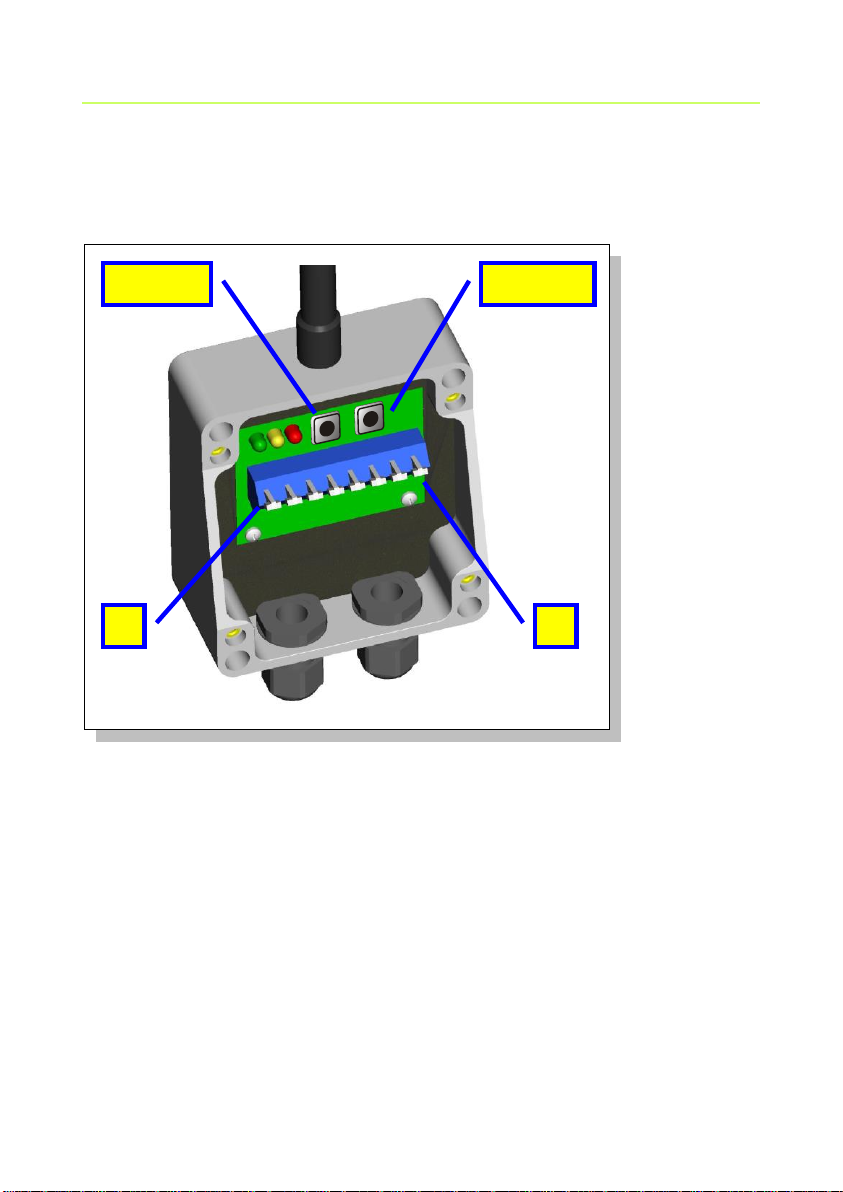
LED
indicators
Antenna
wire
glands
Control elements
LED indicators with the following functions
Green: RF connection:
OFF: no RF connection
Blinking: Searching for partner instrument,
ON: RF connection active
Yellow: Power supply:
OFF: power failure
ON: Power supply in nominal range
Blinking with green LED: matching mode
Red: Error indication:
OFF: system 72working properly
ON: internal error
RF antenna: app. 150 mm (/4), TNC connector. Extension cables and
an extra long antenna (/2) are available as an option.
Cable glands (M16 x 1.5, ATEX certified)
Page 11

Security & Electronic Technologies GmbH Page 11
83 mm
96 mm
M4
Distance of drilling holes:
Horizontal: 83 mm
Vertical: 96 mm
Commissioning
Installation
Mount the supplied RF-antenna with the supplied adapter on the connector
on the housing of the SECU-DATA xxxx.
Mount the SECU-DATA xxxx strain free to the base using 4 pcs. M4 screws:
In case of metallic base material (chassis of vehicles, machinery) try to
maximise the distance between RF-antenna and the base to achieve maximum effective RF range.
Page 12

Page 12 Security & Electronic Technologies GmbH
SECU-DATA xxxM and also SECU-DATA xxxC have internal block terminals (type: WAGO series 256, ATEX certified) for connection of the corresponding external wires.
Important:
Only qualified personnel with appropriate training and authorisation by the
installation manager is entitled to connect SECU-DATA xxxx to an existing
installation. Adhere to all applicable, local safety regulations.
Important:
Check carefully if either the SECU-DATA xxxM on the measurement site or
the SECU-DATA xxxC on the controller location are operated in Ex-zone 1.
If so, then an additional barrier SECU-BAR 125 has to be installed outside
of the Ex-zone 1 between the not intrinsically safe power supply and the
SECU-DATA xxxx to achieve the required level of ignition prevention.
Hint: For SECU-DATA systems using the SECU-DATA 500C as a receiver
the function of the relay contacts can be reconfigured from make contacts
to break contacts, see section Settings-SECU-DATA 500C relay configu-
ration on page 30.
Attention: In case of connection problems SECU-DATA maintains the
last valid information on the receiver output. This is valid for the current output of SECU-DATA 42X/142X and also for the relay outputs of
SECU-DATA 500C/1500C. For overfill prevention applications with
SECU-DATA 600M/710M it is important to ensure the turn-off of pumps
in case of radio failures. This can be achieved by connection the make
contact of Re1 of the SECU-DATA 500C/1500C in series to the “RFstatus” relay contact.
Page 13

Security & Electronic Technologies GmbH Page 13
4-20 mA 4-20 mA
18-36 V
DC
Barrier
SECU-BAR 125
18-36 V
DC
Zone 1 Zone 1
Barrier
SECU-BAR 125
SECU-DATA 420M
SECU-DATA 421M
SECU-DATA 420C
SECU-DATA 421C
Application of SECU-DATA 42xM/42xC (4-20 mA)
If SECU-DATA 42xx is not operated in an explosive area (Ex-zone 1) the
units can be supplied from a standard, not intrinsically safe 24 V DC power
supply, the barrier SECU-BAR 125 is not required.
Receiver site: The barrier SECU-BAR 125 for the SECU-DATA 420C/421C
is required for Ex-zone 1 only. Outside of hazardous areas a SECU-DATA
1420C/141C without a barrier can be used.
Hint: Please, order in addition to the SECU-DATA 42xx set one or two barriers SECU-DATA 125 (order no.: SB125) according to the Ex-protection
requirements.
Page 14

Page 14 Security & Electronic Technologies GmbH
18-36 V
DC
18-36 V
DC
Zone 1
Zone 1
SECU-DATA 500M
Barrier
SECU-BAR 125
Barrier
SECU-BAR 125
SECU-DATA 500C
18-36 V
DC
Barrier
SECU-BAR 125
18-36 V
DC
Barrier
SECU-BAR 125
Zone 1
Zone 1
Probe
Zone 0
NAMUR
SECU-DATA 500C
SECU-DATA 600M
Re1: NAMUR
Re2: Probe fault
Application of SECU-DATA 500M/500C (Relay)
Configuration if transmitter and receiver are in Ex-zone 1
Receiver site: The barrier SECU-BAR 125 for the SECU-DATA 500C is
required for Ex-zone 1 only. Outside of hazardous areas a SECU-DATA
1500C without a barrier can be used.
Application of SECU-DATA 600M (NAMUR)
Receiver site: The barrier SECU-BAR 125 for the SECU-DATA 500C is
required for Ex-zone 1 only. Outside of hazardous areas a SECU-DATA
1500C without a barrier can be used.
Page 15

Security & Electronic Technologies GmbH Page 15
18-36 V
DC
Barrier
SECU-BAR 125
18-36 V
DC
Barrier
SECU-BAR 125
Zone 1 Zone 1
Probe
Zone 0
TrbF
probe
18-36 V
DC
Barrier for
TRbF probe
SECU-DATA 710B
SECU-DATA
500C
SECU-DATA
710M
TRbF: ON-OFF
Re1: TRbF: ON-OFF
Re2: Probe fault
Installation of SECU-DATA 710M/710B (TRbF)
Configuration of SECU-DATA 710M / SECU-DATA 710B / SECU-BAR 125
if transmitter and receiver are in Ex-zone 1:
Receiver site: The barrier SECU-BAR 125 for the SECU-DATA 500C is
required for Ex-zone 1 only. Outside of hazardous areas a SECU-DATA
1500C without a barrier can be used.
Page 16
Page 16 Security & Electronic Technologies GmbH
Button A
Button B
Wiring the connection lines
Open the housing by removing the fixing screws of the lid.
Important:
Install the wiring only after the power supply of the installation has been
turned off.
Follow strictly the safety instructions from the manufacturer; adhere to all
applicable standards, norms and technical guidelines.
Pass all required wires through the cable glands (M16 x 1.5) and fix them
tightly to ensure the water protection of the housing.
Page 17

Security & Electronic Technologies GmbH Page 17
Terminal
Signal, function
1
Plus-pole of power supply (+11 V … +40 V),
reverse polarity protection by two 2 diodes,
ignition prevention level “ib“
2
Ground line of power supply (0 V)
3
Measuring signal 4-20 mA, positive pole,
ignition prevention level “ia“
SECU-DATA 42xM: input, for connection of the
probe
SECU-DATA 42xC: output, for connection of the
evaluation equipment
4
Measuring signal 4-20 mA, negative pole,
ignition prevention level “ia“
SECU-DATA 42xM: input, for connection of the
probe
SECU-DATA 42xC: output, for connection of the
evaluation equipment
5
Not connected
6, 7, 8
Relay contacts, passive, for monitoring the status of the RF-connection
7 is the root, for active RF-connection terminals
6-7 are interconnected, during RF-interruptions
terminals 7-8 are interconnected.
Rated switching capacity: 30 V / 500 mA
Terminals:
SECU-DATA 42xM / 42xC / 142xC (4-20mA)
Page 18

Page 18 Security & Electronic Technologies GmbH
Terminal
Signal, function
1
Plus-pole of power supply (+11 V … +40 V),
reverse polarity protection by two 2 diodes,
ignition prevention level “ib“
2
Ground line of power supply (0 V)
3
SECU-DATA 500M: input Re1, for connection of
the external contact and to terminal 4
SECU-DATA 500C: output Re1, make contact,
for connection of the evaluation equipment
4
SECU-DATA 500M: input Re1, for connection of
the external contact, connected to terminal 6
SECU-DATA 500C: output Re1, make contact,
for connection of the evaluation equipment
Rated switching capacity: 30 V / 500 mA
5
SECU-DATA 500M: input Re2, for connection of
the external contact and to terminal 6
SECU-DATA 500C: output Re2, make contact,
for connection of the evaluation equipment.
Rated switching capacity: 30 V / 500 mA
6
SECU-DATA 500M: input Re2, for connection of
the external contact, connected to terminal 4
SECU-DATA 500C: output Re2, make contact,
for connection of the evaluation equipment
7, 8
Relay contact, passive, for monitoring the status
of the RF-connection.
For active RF-connection terminals 7-8 are interconnected.
Rated switching capacity: 30 V, 500 mA
SECU-DATA 500M / 500C / 1500C (Relay)
Page 19

Security & Electronic Technologies GmbH Page 19
1
2
3
4
5
6
7
8
V+
V-
V+
V+
Re1
Re2
RF
1
2
3
4
5
6
7
8
V-
V+
SECU-DATA 500C
Re2
Re1
RF status
SECU-DATA 1500C
Re1
Re1
Re2
Re2
Connection diagrams:
Transmitter Receiver:
SECU-DATA 500M SECU-DATA 500C / 1500C
Functionality:
The status of the relay contacts Re1 and Re2 connected to the inputs of the
SECU-DATA 500M, is detected and sent per RF-connection to the receiver
module SECU-DATA 500C / 1500C.
Note: There is a current limited voltage present on the inputs for testing the
relay contact status. Therefore the contacts have to be potential free and
insulated, terminals 4 and 6 are internally connected within the SECUDATA 500M. The contact status (“open“ or “closed“) is reproduced on the
relay outputs Re1 and Re2 on the SECU-DATA 500C / 1500C. The contact
function, make or break, can be configured. The rated switching capacity is
30 V / 500 mA.
Important application note: SECU-DATA maintains the last valid value on
the receiver outputs in case of connection problems. To ensure that the
connected controlled device is turned off (very important for overfill prevention systems!) the make contact of relay Re1 has to be connected in series
to the „RF-status“ contact (blue line in the connection diagram).
Page 20

Page 20 Security & Electronic Technologies GmbH
Terminal
Signal, function
1
Plus-pole of power supply (+11 … +40 V), reverse polarity protection by two 2 diodes,
ignition prevention level “ib“
2
Ground line of power supply (0 V)
3
Positive pole for connection of the NAMURprobe.
SECU-DATA 600M applies 8.2 V DC via
1000 Ohms
4
Negative pole for connection of the NAMUR
probe
5
Not connected
6, 7, 8
Relay contacts, passive, for monitoring the status of the RF-connection
7 is the root, for active RF-connection terminals
6-7 are interconnected, during RF-interruptions
terminals 7-8 are interconnected.
Rated switching capacity: 30 V / 500 mA
SECU-DATA 600M (NAMUR)
SECU-DATA 500C / 1550C is used as the receiver, for the terminal connections see section SECU-DATA Relay on page 18 in this chapter.
Functionality:
The connected probe is tested for basic functionality: If the probe current is
below 0.4 mA or higher than 6 mA, relay Re2 of the receiver SECU-DATA
500C is activated per RF-connection, the contact is closed. This can be
used to issue an alarm message. The contact is connected to terminals 5, 6
of the SECU-DATA 500C / 1500C.
During the filling process the contact of relay Re1 SECU-DATA 500C /
1550C is also closed via RF-signals (probe current is more than 2 mA); if
the tank is full (filling is not permissible, probe current below 1 mA) Re1
opens.
See also the important application hint on page 19.
Page 21

Security & Electronic Technologies GmbH Page 21
Terminal
Signal, function
1
Plus-pole of power supply (+22 V … +40 V),
reverse polarity protection by two 2 diodes,
ignition prevention level “ib“
2
Ground line of power supply (0 V)
3
Positive pole for connection of the barrier
SECU-DATA 710B for supplying the TRbFprobe.
4
Negative pole for connection of the barrier
SECU-DATA 710B for supplying the TRbFprobe.
5
Connection of the positive pole of the TRbF
probe
6
Connection of the negative pole of the TRbF
probe
7, 8
Relay contact, passive, for monitoring the status
of the RF-connection
For active RF-connection terminals 7-8 are interconnected.
Rated switching capacity: 30 V / 500 mA
SECU-DATA 710M/710B (TRbF)
SECU-DATA 500C / 1500C is used as the receiver, for the connections see
section SECU-DATA Relay on page 18.
Important:
If the measurement data transmitter is installed in Ex-zone 1 the version
SECU-DATA 710M has to be used in combination with the barrier SECUDATA 125 (for supplying the SECU-DATA 710M) and the additional diodebarrier SECU-DATA 710B (for supplying the TRbF-probe in Ex-zone 0) to
achieve the required ignition protection level.
See also the important application hint on page 19.
Page 22

Page 22 Security & Electronic Technologies GmbH
IN
OUT
U = 18 V ... 36 V DC
in
U = 24 V
I = 125 mA
out
out
Connections of the barrier SECU-BAR 125
Application hints:
SECU-DATA instruments which are to be installed in Ex-zone 1 have to be
supplied from an intrinsically safe power supply to ensure the ignition protection as per ATEX (directive 94/9/EC) EN 60079-0, and EN 60079-11.
The not intrinsically safe power supply with a permissible voltage range of
18 … 36 V is connected to the input IN of the barrier SECU-BAR 125.
SECU-BAR 125 limits the output voltage to max. 25.2 V and the output
current to max. 131.3 mA. The intrinsically safe output OUT is connected to
the power supply terminals of a SECU-DATA xxxx device.
Page 23

Security & Electronic Technologies GmbH Page 23
Remarks for mounting the SECU-BAR 125
SECU-BAR 125 uses an insulated housing for DIN-rail mounting. The insulation provides utmost safety during the installation – short circuits via the
housing, indirect touching of live conductors is impossible.
Please, adhere to all local safety regulations and standards (like DIN VDE
0100, VBG4, etc.) and follow the instructions of the manufacturer and of the
plant manager.
The wiring of the connection terminals is done with the provided selfclearing spring-clips and plus-minus screws.
First of all install the wiring to the SECU-DATA xxxx, and afterwards the
connections to the not intrinsically safe power supply. Snap the SECUDATA 125 simply on to the DIN-rail.
Wiring of the SECU-DATA xxxx:
1. For the wiring use round wires of type: 0,08 – 2.5 mm2 cross section, AWG 28 – 12, flame propagation characteristics as per IEC
60332-1-2, within a round cable to ensure the water protection
2. Strip the wires off app. 5-6 mm
3. Depress each of the levers of the terminal block (Type WAGO series 256, ATEX certified for EEx-i applications) with a small screw
driver
4. Put the stripped wire end into the terminal and release the lever
again
5. Close the SECU-DATA xxxx housing again and mount it to the final
location with the supplied screws in the provided holes of the housing. Take care for correct positioning of the sealing elements. For
metal base planes ensure that there is some space between the
RF-antenna and the metal material to maintain the best effective
range of the RF connection.
Remark: After delivery one cable gland is sealed waterproof with a cap.
This is useful if only one cable gland shall be used.
Page 24

Page 24 Security & Electronic Technologies GmbH
Putting into service a SECU-DATA 42xx
1. Connect the probes and the evaluation equipment to the SECUDATA 42xx units
2. Turn on the DC power supply in the range of +11 V … +40 V
3. Match one pair of instruments together:
Set the same channel block number on both instruments – factory
default is block #6 – details se chapter Settings-Selection of the
RF-channel block
Match the instruments together – detail see chapter Settings-
Matching two SECU-DATA xxxx
4. Both SECU-DATA 42xx modules will establish an RF-interconnection immediately, the green RF-indicators are blinking. After
some seconds they are continuously on – the connection is active.
5. The current on the input of the SECU-DATA 42xM is reproduced
precisely on the output of the SECU-DATA 42xC / 142xC for evaluation with the controller equipment.
6. Check the current values on the evaluation instrument for
plausibility.
The commissioning is completed now successfully.
Page 25

Security & Electronic Technologies GmbH Page 25
Training
The operation of the SECU-DATA xxxx instruments is intentionally very
easy, thus a training as per EC Directive 94/9/EC is not required.
Dismantling
Important:
If you detect any damage of the housing, controls, connection wires or other
connected devices, immediately disconnect the unit from the power supply.
If you cannot ensure the safe operation of the device, immediately shut
down the unit and the respective accessories, secure them against inadvertent switching on, mark them clearly as “defective, out of order” and
send them in to an authorized service facility.
Page 26

Page 26 Security & Electronic Technologies GmbH
Button B
Button A
Settings
Selection of the RF-channel block
SECU-DATA xxxx instruments use one RF-channel out of 64. These are
organized in 8 blocks with 8 channels each. The default setting is block #6.
Two SECU-DATA xxxx instruments are able to communicate only if the
same block for RF-channels is set on both instruments.
Procedure for both units:
1. Open the housing of the SECU-DATA xxxx. Avoid the intrusion of
moisture and pollution while the instrument is open to maintain the
reliability
2. Turn on the power supply of the SECU-DATA xxxx
3. Press the B-button two times shortly
4. The green “RF“-LED will blink several times, the number of light
pulses gives the actual number of the channel block (1 to 8).
5. The light pulses are repeated after a 1 s pause. Each press on button A increments the block number by 1. On the end of the range
the block number falls back from 8 to 1 automatically.
6. An interruption of the power supply aborts the procedure, the original block number remains in memory; the actual one is not stored.
7. The procedure can be finished by pressing the B-button; the actual
block number is stored permanently.
8. Repeat this procedure for the second SECU-DATA xxxx to set the
same block number
If required you may check the block number using steps 1 to 4 as described
above.
Page 27

Security & Electronic Technologies GmbH Page 27
Button B
Button A
Matching two SECU-DATA xxxx
After the delivery SECU-DATA xxxx instruments are not matched together.
This has to be done during setup. Also after replacement of a unit, after
service and repair it might be necessary to repeat the tuning procedure.
Procedure for both units:
1. Open the housing of the SECU-DATA xxxx. Avoid the intrusion of
moisture and pollution while the instrument is open to maintain the
long-term reliability
2. Turn on the power supply of the SECU-DATA xxxx
3. Press shortly on both instruments the A-button
4. The green “RF”-LED and the yellow “Power“-LED on the SECUDATA xxxx start blinking alternately – the instruments are in the
matching mode now
5. After completion both instruments perform automatically a RESET
– the red LED flashes shortly. If the tuning process is not successful you can abort it by pressing shortly the button A – the original
settings remain in memory
6. Now the green “RF”-LED and the yellow “Power”-LED on both instruments are continuously on – the matching procedure is finished
successfully and the RF-connection is established.
Page 28

Page 28 Security & Electronic Technologies GmbH
Contact 6-7 is closed
as long as the RFconnection is established.
This circuitry provides
best reliability: if the
RF-connection is lost
or a power failure of
the SECU-DATA xxxx
occurred, the contact
opens and the alarm
lamp will be turned on
immediately.
Inverter relays can be
used also. Additionally the contact function
can be configured.
7
6
Monitoring the RF-status, alarm generation
Depending on the application it might be important to monitor the status of
the RF-connection and to generate an alarm indication in case of interruptions.
Important: During interruptions of the RF-connection SECU-DATA xxxC
instruments freeze the latest transmitted value and keep them on the output.
The status of the RF-connection can be tested via relay contacts.
SECU-DATA xxxx incorporate a relay contact, a make contact, which is
closed as long as the connection is active. The rated switching capacity of
the contact is 30 V / 500 mA.
Hint
Also the instruments SECU-DATA xxxM located on the measurement side
are equipped with such a relay contact with the same functionality. Thus an
alarm indication can be realised on the measurement site too.
If you want to realise an alarm signal (e.g. by a lamp) on the controller site
make use of this contact (principle diagram):
SECU-DATA 42xM, 42xC, 142xC, 600M
Page 29

Security & Electronic Technologies GmbH Page 29
Contact 7-8 is closed as
long as the RFconnection is established. During RFinterruptions it is open
and the lamp goes on to
indicate an alarm condition.
The rated switching capacity of the contact is
30 V / 500 mA.
7
6
8
The make contact can be used for variants:
SECU-DATA 500M, 500C, 1500C, 710M
Page 30

Page 30 Security & Electronic Technologies GmbH
Mode
Relay RF
Re1
Re2
1
normal
make
make
2
inverse
make
make
3
normal
break
make
4
inverse
break
make
5
normal
make
break
6
inverse
make
break
7
normal
break
break
8
inverse
break
break
SECU-DATA 500C relay configuration
After delivery the relay contacts are configured as make contacts, which
can be changed to break contacts if required.
Procedure:
1. Turn on the power supply of the SECU-DATA 500C / 1500C
2. Press and keep depressed the button A and press two times the
button B. The green “RF“-LED starts blinking, the number of pulses
indicates the relay mode:
make … contact closes if the relay is activated.
break … contact opens if the relay is activated.
3. Pressing of button B saves the settings
Hint: On all the other SECU-DATA xxxx instruments this configuration
is also provided but for the RF-relay function only, thus mode 1 and 2
are available only.
Page 31

Security & Electronic Technologies GmbH Page 31
Maintenance
Instruments of the SECU-DATA xxxx product range do not need any
maintenance, no user serviceable components are inside of the housing.
Important:
Repair and service tasks can be done by qualified service personnel only.
This is the only way to maintain the required level of ignition prevention.
The service activities carried out are documented and these files are kept in
archives for at least 10 years.
Warranty
For the actual services and conditions see the internet home page
www.secu-tech.at, see the GTCS – General Terms and Conditions of Sale.
Disposal
SECU-DATA instruments must not be disposed of via the municipal waste
collection system.
Security & Electronic Technologies GmbH. takes back used SECU-DATA
instruments for appropriate disposal for a small charge.
The symbol for disposal via qualified recyclers is attached visibly and permanently on the instrument.
Page 32

Page 32 Security & Electronic Technologies GmbH
Troubleshooting
Problem: The RF-connection cannot be established
Solution 1:
Check:
Is the supplied antenna mounted correctly?
Are there obstacles which block the propagation of the RF waves?
Is the distance between transmitter and receiver less than 1 km?
Select an optimal position for the antenna, antenna extension cables are
available as an option.
Solution 2:
Interrupt shortly the power supply of both SECU-DATA xxxx units and turn
them on again. The modules will establish a new connection and they will
search for free undistorted RF-channels automatically.
Solution 3:
If this does not solve the problem match together the two instruments again.
For the procedure see chapter “Settings - Matching two SECU-DATA
xxxx “
Solution 4:
If the tuning cannot be carried out successfully check the number of the RFchannel block. Both instruments have to operate within the same block of 8
RF-channels.
For the procedure of verification and re-definition of the RF-channel block
see chapter “Settings - Selection of the RF-channel block”
If all measures described in this chapter do not solve your problem then
send in the modules with a short description of the problem and with a copy
of the delivery note (in case of warranty claims) to the manufacturer or to an
authorised service facility.
Page 33

Page 33 Security & Electronic Technologies GmbH
Technical specification
Power supply concept
According to ignition protection requirements the following power supply
systems are available:
For standard applications outside Ex-zones SECU-DATA xxxx is supplied
from a standard DC supply in the range of +11 V … +40 V. If the transmitter
and/or the receiver are installed in Ex-zone 1 a SECU-BAR 125 barrier has
to be inserted in between to achieve intrinsic safety as per EN 60079-11.
Radio frequency data transfer
Transmitting and receiving frequency in the 433 MHz band, very narrow
bandwidth, 64 channels in 8 frequency blocks (selectable on the instrument), 25 kHz channel separation, effective range up to 1 km or even more
in open areas, best temperature stability, insensitive to distortions, automatic selection of an undistorted channel, RF data transmission rate: 4.800
Baud (data bits/s, the effective data rate is 2.400 Baud). Data loss is prevented by using a CRC16 error correction.
A potential-free relay contact is used to monitor the status of the RF connection, e.g. to issue an alert in case of an RF interruption
Technical Specification
ATEX certificates: see page 5
Display:
Fuses:
RF-module:
Housing of SECU-DATA xxxx
Dimensions (l x w x h): 146 x 97 x 60 mm
Weight: app. 650 g incl. antenna
Antenna: app. 150 mm (/4), connector: TNC
Construction: mouldered with PU 403 – WEVO,
PTB-registered
Protection: IP 67,
Material, colour: Deltacom ASA 4501 EC 6, black
CTI value: 250
3 LEDs
Temperature fuses
Conform to ETSI EN 300 220 (5/1999/EG R&TTE)
(without antenna and cable glands)
SECU-DATA 710B:
IP 20
Page 34

Page 34 Security & Electronic Technologies GmbH
Rated specification of SECU-DATA xxxx
Supply voltage: 11 V ... 40 V DC,
intrinsically safe for applications in Ex-Zone 1
Power consumption (without probe): max. 1.2 W
Ambient temperature: -30°C ≤ Ta ≤... +75°C
ATEX - parameters for all SECU-DATA xxxx versions:
Attention: For applications in explosive areas all inputs have to be
connected to intrinsically safe lines only.
Power supply (pins 1-2, ignition protection: “ib”):
UI = 25.2 V, II = 131.3 mA, CI ~ 0, LI ~ 0
RF-relay (pins (6-)7-8, ignition protection: “ib”):
UI = 30 V, II = 500 mA, CI ~ 0, LI ~ 0
Technical specification of SECU-DATA 42xx - 4-20 mA
ATEX - parameters:
SECU-DATA 420M/421M–current input (pins 3-4, ign. protection: “ia”):
UO = 25.2 V, IO = 146.8 mA, CO = 107 nF, LO = 2 mH
SECU-DATA 420C/421C–current output (pins 3-4, ign. protection: “ib”):
UI = 30 V, II = 150 mA, CI = 12 nF, LI ~ 0
Measurement uncertainty SECU-DATA 421M/421C - 16-Bit:
Typical at 25°C: ±0.02% of measured value
Max. (-30°C … 75°C): ±0.1% of measured value
Resolution: 0.4 µA
Measurement uncertainty SECU-DATA 420M/420C - 12-Bit:
Typical at 25°C: ±0.1% of measured value
Max. (-30°C … 75°C): ±0.3% of measured value
Resolution: 6 µA
Rise time: < 0.5 s
Specification of SECU-DATA 500M/500C - Relay
ATEX parameters :
SECU-DATA 500M
Relay inputs (pins 3-4, 5-6, ignition protection: “ib”):
UO = 10 V, IO = 1 mA, CO = 1 µF, LO = ~ 0
Page 35

Security & Electronic Technologies GmbH Page 35
Probe current
Re1
Re2
Meaning
0 … 0.4 mA
OFF
ON
Probe fault, “interruption”
1 … 2 mA
ON
OFF
Filling is in progress
2 … 6 mA
OFF
OFF
Tank full
> 6 mA
OFF
ON
Probe fault, “short”
Probe current
Re1
Re2
Meaning
0 … 6 mA
OFF
ON
Probe fault, “interruption”
6 … 40 mA
ON
OFF
Filling is permissible
>42 mA
OFF
OFF
Filling not permissible
>105 mA
OFF
ON
Probe fault, “short”
SECU-DATA 500C
Relay outputs (pins 3-4, 5-6, ignition protection: “ib”):
UI = 30 V, II = 500 mA, C
For the transmission of the status of the two relay contacts no further specification is required. Rated switching capacity: 30 V / 500 mA.
Technical specification of SECU-DATA 600M - NAMUR
ATEX parameters:
NAMUR-probe (pins 3-4, ignition protection: “ia”):
UO = 10 V, IO = 14 mA, CO = 1 µF, LO = 2 mH
Switching thresholds depending on the current flow through the
NAMUR probe:
Technical specification of SECU-DATA 710M - TRbF
ATEX parameters :
Connector for SECU-DATA 710B (pins 3-4, ignition protection: “ia”):
UI = 23.1 V, II = 145.8 mA, CI ~ 0, LI ~ 0
TRbF-probe connector (pins 5-6, ignition protection: “ia”):
UO = 23.1 V, IO = 145.8 mA, CO = 60 nF, LO = 2 mH
Thresholds for the current flow through the TRbF probe:
~ 0, LI = ~ 0
I
Page 36

Page 36 Security & Electronic Technologies GmbH
Specification of SECU-DATA 710B – barrier for supplying the TRbFprobe
Standard housing for DIN-rail mounting as per EN 50022
Dimensions (W x D x H): 25 x 70 x 103 mm
Material: ABS (Teluran), grey
ATEX-parameters:
Intrinsically safe side (ignition protection: “ia”):
UO = 23.1 V, IO = 145.8 mA, CO = 60 nF, LO = 2 mH
Rated specification of the active barrier SECU-BAR 125
Standard housing for DIN-rail mounting as per EN 50022
Dimensions (W x D x H): 25 x 70 x 103 mm
Material: ABS (Teluran), grey
Protection : IP20
Ambient temperature: -30°C ≤ Ta ≤ ... +75°C
Electrical specification:
Nominal values: UN = 24 V
Input voltage: Range: 18 V… 36 V DC, UM = 36 V
Output: UO = 25.2 V, IO = 131.3 mA,
CO = 107 nF, LO = 2 mH
Norms, standards applied
ATEX (EC-directive 94/9/EC), EN 60079-0:2004, EN 60079-11:2007, EN
61241-0:2006, EN 61241-11:2006, EN 60529, ETSI EN 300 220 (EC directive 5/1999/EG R&TTE).
Connectors of SECU-DATA xxxx
Attention: For applications in explosive areas all inputs have to be
connected to intrinsically safe lines only.
The connecting wires (round cables have to be used) are fed into the housing via cable glands (M16 x 1.5, type SKINTOP) with appropriate strain
relief to a terminal block (type WAGO series 256).
The number of wires and their functionality depends on the SECU-DATA
model, see the appropriate section in this document.
Cable glands:
Type: SKINTOP
Material: Body: Polyamide, halogen free, sealing: EPDM
Dimensions: M16 x 1.5
Page 37

Security & Electronic Technologies GmbH Page 37
Page 38

Page 38 Security & Electronic Technologies GmbH
Index
alarms ......................................................................................................... 28
antenna extension cable ............................................................................... 9
ATEX certificates ........................................................................................ 33
block terminals ............................................................................................ 12
cable glands ................................................................................................ 36
channel block .............................................................................................. 26
channel separation ..................................................................................... 33
Connection configurations .............................................................. 13, 14, 15
connection wires ......................................................................................... 16
Connectors .................................................................................................. 36
Control elements ......................................................................................... 10
Dimensions ................................................................................................. 33
DIN-rail ........................................................................................................ 23
directive 94/9/EC ........................................................................................ 25
EN 60079-14 ................................................................................................. 4
ETSI EN 300 220 .................................................................................. 36, 37
Ex-zone 1 .................................................................................................... 12
LED indicators............................................................................................. 10
operating temperature ................................................................................ 34
power consumption ..................................................................................... 34
RF antenna ................................................................................................. 10
RF-LED ....................................................................................................... 27
SECU-BAR 125 ........................................................................................ 8, 9
terminal block .............................................................................................. 23
terminals ..................................................................................................... 17
wire type ...................................................................................................... 23
Page 39

Security & Electronic Technologies GmbH Page 39
Notes:
Page 40

Telefon: +43 2256 20177-0
Fax: +43 2256 20177-11
E-Mail: office@secu-tech.at
Homepage: www.secu-tech.at
Aumühlweg 3/1
A-2544 Leobersdorf
Austria
Security & Electronic Technologies GmbH
Other products:
RF Fuelling and Overfill Prevention System:
LRC – Level Remote Control
Tank contents instruments LC 100 series
For heating oil tanks, water tanks, waste oil tanks,…
In the distribution line:
Level Control Systems
Industrial probes from several manufacturers
Tank content measurement systems
See our homepage:
 Loading...