

Page 1
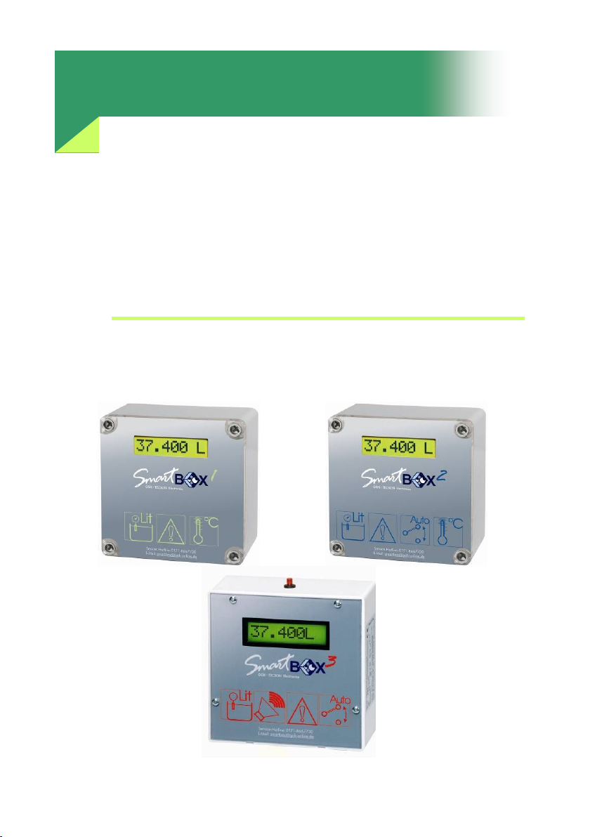
Installation, Operating Manual
SmartBox 1, SmartBox 2, SmartBox 3
Electronic contents indicators with
control functions
Security & Electronic Technologies GmbH
Page 2

Page 2 Security & Electronic Technologies GmbH
TOC – Table of Contents
Safety Instructions ...................................................................................................... 2
General ........................................................................................................................ 3
Design .......................................................................................................................... 3
Operating media .......................................................................................................... 4
Installation ................................................................................................................... 4
Installation of the SmartBox ........................................................................................ 5
Startup ......................................................................................................................... 9
Examples for programming ......................................................................................... 11
Notes on programming ............................................................................................... 12
Operation .................................................................................................................... 17
Performance check .................................................................................................... 17
Maintenance ................................................................................................................ 17
Repair ......................................................................................................................... 17
Technical specification ............................................................................................... 18
Accessories ................................................................................................................ 19
Version: Rev. 2.0 Date: 2008-07
Document: LI512
©SECURITY & ELECTRONIC TECHNOLOGIES GmbH
Important: The technical specification stated in this document is
subject to modification by the manufacturer without any notice.
Safety Instructions
SAFETY INFORMATION for water-polluting operating media:
Any material leakage occurring during maintenance must be collected.
Observe the respective legal regulations!
Page 3

Security & Electronic Technologies GmbH Seite 3
General
The electronic tank management system SmartBox 1, SmartBox 2, and SmartBox 3
can be used for monitoring of the liquids contained in un-pressurized liquids
tanks. In addition to the registration of tank contents, other functions can be
implemented by system extensions, e.g. temperature measurement, data
telecommunication, or connection to master-control systems of the building.
SmartBox 2 has additional relay control functions, e.g. for activating external
alarm devices, solenoid valves, or the dry-run protection function of pumps.
SmartBox 3 has relay control functions and an acoustic transmitter for minimum
level messaging. The alarm tone can be deactivated (acknowledged ) with
a button.
Thanks to its modular design, the system can be equipped with additional
modules, e.g. with analogue interface or a GSM module for
telecommunication.
The indicated measurements are not applicable for invoicing. The measuring
probe is not a safety device, not even in connection with an electronic
indicator. Accordingly, it will not replace a limit monitoring indicator at the tank.
To operate the device as intended and to observe the warranty conditions, it
is imperative that you adhere to this Installation and Operating Manual and
hand it over to the user.
Design
The SmartBox 1 has an 8-digit LC-display and a measuring input for connecting
the probe. The SmartBox 2 has additionally 2 programmable relays with make
and break switching output. As a standard, the measuring probe can be
installed with tank connecting thread G1, G1½, or G2.
Page 4

Page 4 Security & Electronic Technologies GmbH
Operating media
Fuel oil EL acc. to DIN 51603-1
Petroleum fire point > 55°C
Diesel fuel DK acc. to DIN EN 590
Alcohol fire point > 55°C
FAME (Biodiesel) acc. to DIN EN 14214
Glycerin
Hydraulic oil
Glycol
Motor oil
Brake fluid
Vegetable oil
Water
Urea solution e.g. AdBlue acc. to DIN 70700
Petrol with fire point < 55°Conly with SmartBox in EX-version
Installation
Check the indicator and the probe element for transport damages before start
of the installation. Indicator and measuring probe must only be installed and
commissioned by qualified personnel. This requirement also applies to
maintenance and repairs. In case of improper installation, any warranty
claims will be forfeited.
- The device must only be installed into tanks which are not operated
under pressure. This is to say that the tanks must be equipped with a
tank ventilation according to the regulations. Additionally, heating oil
and fuel tanks must have a functioning limit monitoring indicator as
overfill protection.
- The inlet of the probe cable at the tank must be sealed in such a way
that no smell will permeate or water will penetrate under operating
conditions.
Page 5
Security & Electronic Technologies GmbH Seite 5
Notes on installation
Expert installation under observation of the technical regulations for planning,
construction and operation of the system as a whole is the precondition for
faultless functioning of the contents indicator. These regulations also include
the accident prevention regulations of the employers‟ liability insurance
associations, the VDE regulations, and the installation and operating
instructions for the fluid tank. The housing of the indicator is suitable for wall
mounting and is connected to the 230 V mains supply. Under normal
circumstances, the indicator must be operated with the housing cover closed.
It is installed and commissioned by the qualified technician while the unit is
open.
Warning: Keep away from the area of the 230 V terminal.
Installation of the SmartBox
Mount the indicator to the wall in a suitable position. After loosening the four
screws, open the indicator by removing the cover. Mount the unit to a smooth
vertical wall by means of four dowels. Mount the housing of the indicator by
the four fixing holes by means of the enclosed screws. Take care not to
damage the housing! After connecting the terminals and setting the unit up,
re-screw the cover.
Warning: The indicator must not be installed in areas subject to explosion hazards!
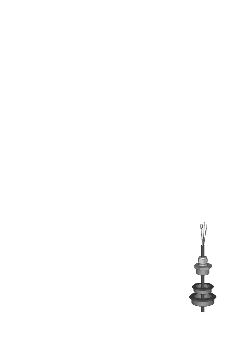
Mounting of the probe
For welded basement steel tanks and buried tanks,
the probe is installed by means of the enclosed screw
fitting with cable bushing.
In most cases of installation to basement tanks,
the fuel gauge with float used before is dismounted so
that its opening can be used to screw in the probe unit.
With buried tanks, there usually is a free opening to
screw in the probe element; it will be closed with a
removable filler plug.
Installation of the probe into the tank by means of
the enclosed screw fitting (see illustration):
Page 6

Page 6 Security & Electronic Technologies GmbH
If applicable, switch the oil burner off and lock the take-off pipe of the
tank.
Clear the opening at the tank.
Push the screw fitting, if applicable with reduction bush(es), over the
probe cable and insert the probe into the tank.
Seal the screw fitting smell-tight (e.g. with PTFE tape) and screw it into
the tank cover.
Lower the probe into the tank until the probe head touches the tank floor
(you will feel it via the cable). Then, screw down the cable gland to fix the
cable. Optionally, the probe can also be fixed in a lying position on the
tank floor.
Usually, it is not necessary to perform a probe zero adjustment.
Re-open the take-off line of the tank and reactivate the oil burner if
applicable. Check the function of the oil burner.
Electrical Installation
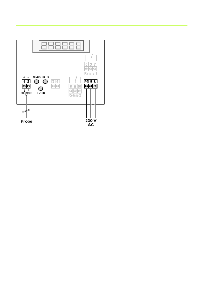
Connection line between indicator and probe:
Voltage: Probe element 20 V DC
Connection: Probe connection cable to terminals 1 (red) and 2 (black)
(see figure below)
Air capillaries: The cable must be installed in such a way that pressure
equalization with the ambient air is ensured but no moisture
can penetrate into the cable end.
Extensions: The probe cable can be extended by max. 200 m - e.g. with
cable type NYM or YR (moisture-proof) or NYY (ground) and
with min. cable cross-section 2 x 0.4 mm2.
For cable extension in the dome or outdoors, a
waterproof connection box with special pressure
equalization filter must be used (accessory).
Shield: If the probe cable (or extension) runs close to power lines, a
shielded signal line should be used (connect shield to
PE terminal).
Connection of supply voltage:
Voltage: 230 V AC 50 Hz
Connection: Terminals PE, N + L to the indicator (cable is not part of the
delivery)
Page 7
Security & Electronic Technologies GmbH Seite 7
Connection
probe cable
1+ = red
2- = black
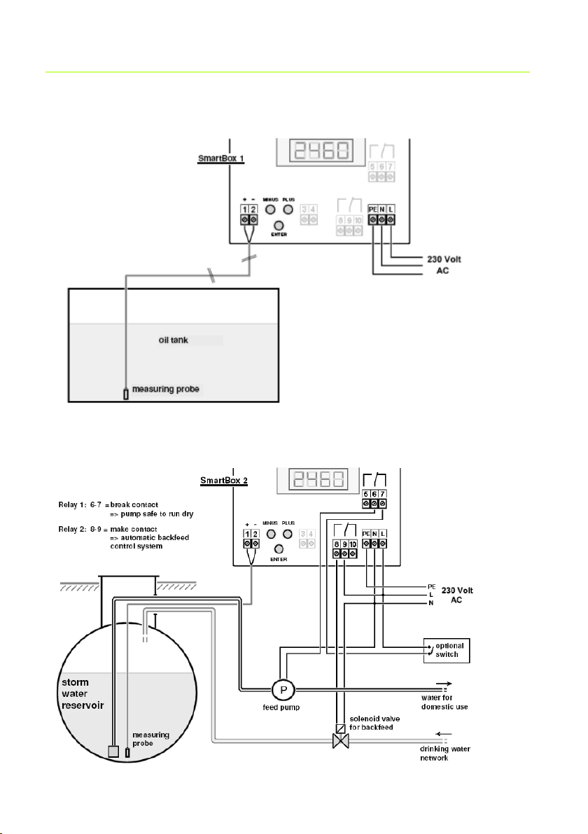
Connection of the relay contacts of SmartBox 2 and SmartBox 3
The indicator SmartBox 2 has two relays (SmartBox 3 1 relay) for the connection
of external control circuits or for activating external alarm or signal devices. In
case of failure of the unit and if the fill level (and optionally the temperature) is
above the selected limit, the contact of relay terminals 6 + 7 and 9 + 10 are
closed, or 5 + 6 and 8 + 9 are open- see the legend on the PCB in the unit.
Switching voltage max.: 250 V AC
Switching current max.: 3.5 A
Connection: closed for alarm open for alarm
Relay 1 terminals 5 + 6 terminals 6 + 7 SmartBox 2
Relay 2 terminals 8 + 9 terminals 9 + 10 SmartBox 2, 3
Connection of interface to SmartBox 4, SmartBox 5 or PC-Link
The measured values can be transmitted to the SmartBox 4, SmartBox 5 or the
PC-Link set via the integrated interface “SERIAL LINK OUTPUT” terminals
3 + 4.
Page 8
Page 8 Security & Electronic Technologies GmbH
Heating oil tank - wiring example Smart Box 1
Rain water reservoir - wiring example SmartBox 2
Page 9

Security & Electronic Technologies GmbH Seite 9
Setting a
parameter:
Press ENTER to call the setup mode.
Select the desired setting parameter via PLUS. Press
ENTER to call up the value selection for the parameter.
Set the value with PLUS/MINUS, press ENTER to save.
Quitting the
setup mode:
You can quit the setup mode at any time.
Select 8. Exit and press ENTER to go back to the
standard display mode.
Step
Input function
Input value
1. Probe
Select probe measuring range (see type
label of the probe) - default value is
250 mbar
______mbar
2. Fluid
(medium)
Select the medium, e.g.:
- heating oil (default): Heat.oil
- Diesel: Diesel
- select other stored media with + / - or
enter density value ...kg/m3
For unknown density values, see the
Notes on Programming
__________
3. Tank
(tank shape)
Select the tank shape, e.g.:
- linear (default): Linear
- cylindrical horizontal: Cyl.
- cyl. horizontal 50 to 100 m³:Cyl.>50m3
__________
4. Volume
(tank volume)
Enter tank volume (or maximum fill
level):e. g.: 20.000L
Important: Please see a volume table for
the highest value, if available.
For a 100 m³ cyl. buried tank, this may for
example be the value 100 600 litres.
_________L
Startup
After the contents indicator has been installed, it can be started up. Before
programming, you need to ascertain the tank data and enter the values into
the right column Input value of the following table. Then, enter the values for
the individual entry steps. Optionally, the device can also be programmed as
explained in the enclosed Quick Guide.
Page 10

Page 10 Security & Electronic Technologies GmbH
5. Height
(tank height
or max. filling
height)
Enter inner tank height in mm: e. g.:
2.500 mm (max. value = 9.999 mm)
(height without dome)
Important: Please see a volume table for
the highest value, if available.
For a 100 m³ cyl. buried tank, this may be
f. e. the value 288 cm = 2.880 mm.
Steps 6 + 7 are only required for SmartBox 2 and SmartBox 3
SmartBox 2:
6. Relay1
or
SmartBox 3:
6. Beeper
(acoustic
alarm
transmitter)
Enter relay switch points as percentage
from 01 to 99 (and/or as °C value from
-99 to +99) – only for a probe with
temperature measuring function)
deactive activate with + / - to
active press Enter to confirm
On: 10% ON: set with + / - Enter
Off: 12% OFF: set with + / - Enter
On: +0°C ON: set with + / - Enter
Off: +0°C OFF: set with + / - Enter
Deactivate the relay and the beeper via
deactive or input of 0% or 0°C (both for
On and Off).
On ___%
Off ___%
On ___°C
Off ___°C
7. Relay2
See 6. Relay 1 for the data for Relay 2
8. Exit (quit)
Press Enter to return to display mode
After performing entry steps 1 - 7, the programming process is completed.
After confirmation of step 8 “Exit“, the device automatically returns to
standard display mode; the current tank contents is shown in the display.
Special functions are available under entry steps 9 to 13 (see later).
After the end of setup, do not forget to re-screw the housing cover!
Page 11

Security & Electronic Technologies GmbH Seite 11
Examples for programming
Example 1 Basement tank for 6000 litres heating oil, litre indication,
linear steel tank
Inner height 165 cm, (fill level 125 cm)
Standard probe TDS-6023 0 – 250 mbar
Step Entries/selection
1. Probe 250 mbar 250mbar
2. Medium: heating oil Heat.oil
3. Tank shape: linear Linear
4. Tank volume: 6000 litres 6000L (set with +/- keys)
5. Inner tank height: 165 cm 1.650mm (set with +/- keys)
6. Relay 1 – no function deactive
7. Relay 2 – no function deactive
8. Exit press ENTER to see the indication e.g. 4550L
Example 2 Buried tank, cylindrical, horizontal, for 100.600 litres Diesel oil
Inner height 2.886 m, (fill level 54 cm)
Standard probe TDS-6023 0 – 250 mbar
Step Entries
1. Probe 250 mbar 250mbar
2. Medium: Diesel Diesel
3. Tank shape cyl. horiz. >50m³ Cyl. >50m3
4. Tank volume: 100.600 l 100600L (exact value from volume table)
5. Inner tank height: 288.6 cm 2886 (exact value from volume table)
6. Relay 1 – no function inactive
7. Relay 2 - no function inactive
8. Exit press ENTER to see the indication e.g. 12.800L
Tank with inner casing
For tanks with inner casing (e.g. cyl. horizontal or basement-welded tanks),
the entries for inner height and volume should be adjusted.
Examples:
Wall thickness of inner casing 0.5 cm reduce value for inner height by
approx. 1 cm, reduce volume for 10 m³ by 1.3%, for 20 m³ by 1%, for 50 m³
by 0.8% and for 100 m³ by 0.7%.
Page 12

Page 12 Security & Electronic Technologies GmbH
Menu
item
Setting
Description
0. Exit
Back to display mode
1.
Probe
100mbar
150mbar
250mbar
500mbar
1000mbar
2000mbar
3000mbar
5000mbar
Set mbar
Cal mode
Tank height heating oil up to 1.2 m – water up to 1 m
Tank height heating oil up to 1.8 m – water up to 1.5 m
Standard probe - tank height heating oil up to 3 m –
water up to 2.5 m
Tank height heating oil up to 6 m – water up to 5 m
Tank height heating oil up to 12 m – water up to 10 m
Tank height heating oil up to 24 m – water up to 20 m
Tank height heating oil up to 36 m – water up to 30 m
Tank height heating oil up to 60 m – water up to 50 m
Entry of a specific probe with different measuring
range Is only indicated if item 10. Set h or 11. Set V
has been activated
Wall thickness of inner casing 2 cm reduce value for inner height by
approx. 4 cm, reduce volume for 10 m³ by 5%, for 20 m³ by 4%, for 50 m³ by
3% and for 100 m³ by 2.5%.
Example 3 Well, 7.50 m maximum water level from ground of the well
(fill level 4.20 m), relay switching function is desired.
Probe TDS-6029 (measuring range 0 – 1000 mbar), indication in m water
column.
Step Entries
1. Probe 1000 mbar 1000mbar
2. Medium: water H2O
3. Tank shape (well): linear Linear
4. Volume 7500l
(indicated in m) 7500L (set with +/- keys)
5. Inner tank height 7.50m 750 cm (set with +/- keys)
6. Relay1 – ON at <05% -
OFF at >10% active On: 05% Off:10%
7. Relay2 – no function
8. Exit press PLUS key to go to
12. Unit – indicated unit: m Unit: m
13. Rounding: auto auto (just confirm with ENTER)
14. Exit press ENTER to see the indication e.g. 4.20m
Notes on programming
Page 13
Security & Electronic Technologies GmbH Seite 13
2.Fluid
Medium
Heat.oil
H2O
Diesel
BioD
RME,FAME
Rapsoil
Palmoil
Motoroil
AdBlue
Normal-B
Super-B
Set kg/m3
Cal mode
0.845 - default setting
0.999
0.830
0.880
0.880 (rapeseed, methyl ester, fatty acid methyl ester)
0.915
0.910
0,865
1.090
0.743
0.750
Entry of a specific density value
is only indicated if item 10. Set h or 11. Set V has been
activated
If the density of the stored medium is unknown, the reference height can be
entered in menu item10. Set h. To this end, determine the current fill level in
mm, deduct 10 mm from it and enter the resulting value - click YES to confirm
the entry. Should the current fill level be smaller 75%, we urgently
recommend to adjust the value after the next refuelling to achieve a good
measuring accuracy.
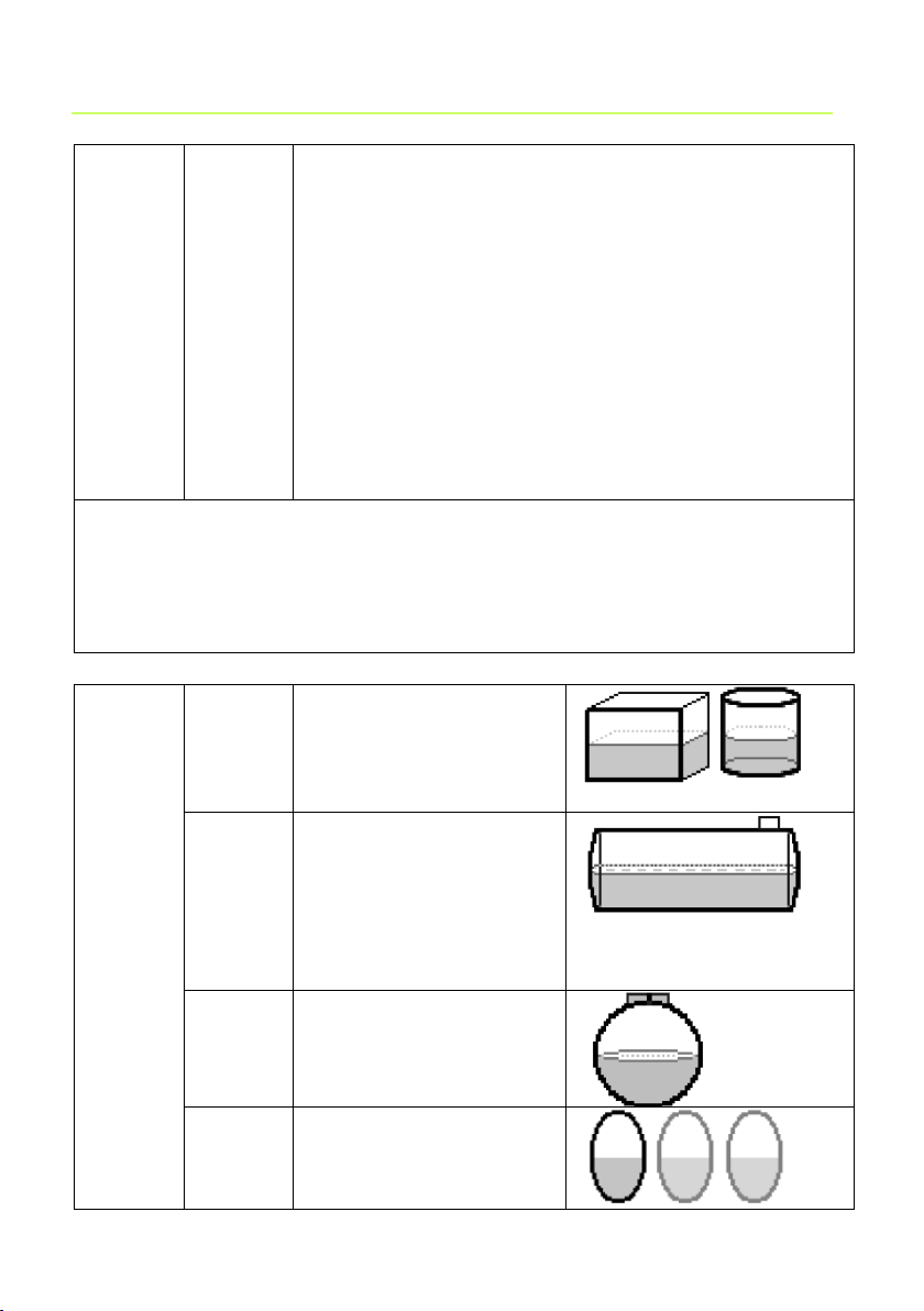
3. tank
tank
shape
Linear
Default setting
linear tank, rectangular
tanks, vertical cylinders,
basement-welded steel
tanks.
Cyl.
cylindrical tank
(optionally, see
Cyl.>50m³), horizontal
cylinders; tubular tanks,
max. 45 m³; typical
shape for steel outdoor
or buried tanks.
Ball
spherical tank; buried
tanks with spherical
basic shape; frequently
plastic buried tank(GRP).
Oval
oval basement tanks;
typical shape of GRP
tanks and single-walled
sheet metal tanks
Page 14
Page 14 Security & Electronic Technologies GmbH
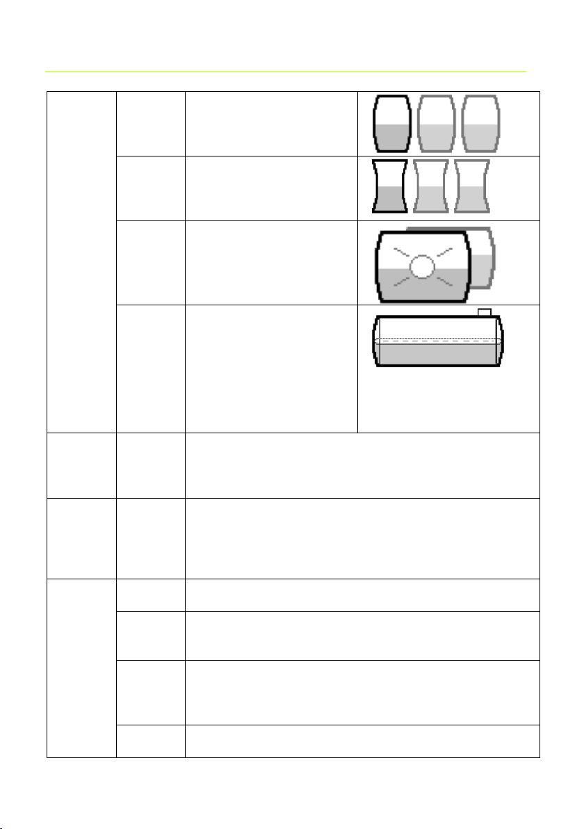
Convex
Plastic battery tanks,
convex, slightly bellied
shape, alternative to
linear
Concav
e
Plastic battery tanks,
concave, slightly cavedin shape, alternative to
linear
Plastics
Plastic tank with recess.
Plastic tank with a large
recess (hollow) in the
centre (without tape
bindings)
Cyl.>50
m³
large cylindrical outdoor
tank 50.000 litres to
100.000 litres; a special
bearing chart conversion
table can be ordered
specifically for large
cylindrical tanks of 50 m³
to 100 m³.
4.
Volume
tank
volume
xxx.xxxL
Default setting is 0L. 0L is an invalid value.
This parameter must be set in all cases.
5.
Height
Inner
tank
height
x.xxx
mm
(or cm)
Default setting is 2.000 mm (the maximum value is
9.999 mm) - for probes from 1.000 mbar, the height is
indicated/set in cm, not in mm.
6.
Relay1
deactive
active
Default setting (enter on deactive go to next entry
step). Enter on active results in the next „On‟ step
On:
10%
10% is the default setting, range is 0..99
Relay and beeper switches ON if the content of the
tank falls below a limit of e.g. 10%.
Off:12%
12% is the default setting (hysteresis)
Relay and beeper switches OFF again if the content of
the tank rises above a limit of e.g. 12%. If On=0% and
Off=0%, no fill level switching function is active.
On: +0C
Only if a temperature adapter is available; range is
-99C .. +99C When On=0C and Off=0C, no
Page 15

Security & Electronic Technologies GmbH Seite 15
temperature switching function is active
Relay switches ON if the temperature falls below a limit
of e.g. 15°C.
Off: +0C
Relay and beeper switches OFF again if the
temperature rises above a limit of e.g. 17°C
(hysteresis).
7.
Relay2
For entries for Relay2, refer to 6.Relay1
8. Exit
Back to display mode
9.
Offset
ESC
Calibrat
Default
Zero point adjustment (probe offset)is indicated only
after a calibration has been performed
10.
Set h
xxxx
mm
Possibility to enter reference height for 2-pointmeasurement, for a different probe measuring range,
or if density is unknown. Deduct 10 mm from the
current fill level as measured*, and enter the resulting
value. If tank height “5. Height” has been indicated in
cm (e.g. for probe measuring range from 1,000 mbar),
the value will be indicated in cm here!
Cal: No
Cal: Yes
If activated (Yes), a confirmation dialog follows
because from now on, the system will not calculate
with the density as entered but with a special factor.
Then, “Cal Mode” is indicated in step 1+2. If this entry
is made while the tank is almost empty, it is advisable
to perform a readjustment later on, see 11.Set V.
11.
Set V
xxx.xxxL
Readjustment of the fill level indication with +/- key.
Cal: No
Cal: Yes
See 10.Set h
12.
Unit
Unit:
m3Unit:
%Unit:
m
Default setting (3 decimal points: 999,900L)
(2 decimal points: 75.50 m3 )
(2 decimal points: 99.50 % )
(2 decimal points: 2.50 m )
13.
Round
Auto
Off
2, 5, 10,
20, 50,
100
Default setting (increments of 1). In dependence on the
preset volume, one or two zeros are added. This is to
say that a selected rounding value 2..100 refers to the
4th indicated position (e.g. for a 100.000L tank, 10=
stands for 1.000L rounding)
14. –19.
Exit
Back to display mode
20. LCD
Contr 52
Set the contrast of the LC-display
21. Info
Shows the following:
Page 16

Page 16 Security & Electronic Technologies GmbH
Software version V1.00
Serial number SN1234 X0xxxx Bxxxx
22. Test
Indication of the current mA measured value and the
hex value for the A/D-converter
23.
TestR
Rel1 ON
Rel1
OFF
Rel2 ON
Rel2
OFF
Relay test
24. Init
Sure:
No
Sure:
Yes
Abort
Clear all settings (factory settings)
26. Exit
Back to display mode
Error Code
Significance
Error E1
The set value is invalid
Error E2
Measured value too small (<3mA => probe defective)
Error E3
Measured value too large for zero point calibration
(probe must not be immersed)
Error E4
Not defined
Error E5
Not defined
Error E6
Set height is too great (measured value is too small the probe must be immersed)
Error E7
Set volume is too great (measured value is too small the probe must be immersed)
Error E8
Measured value is too great (probe short-circuited,
defective, or incorrectly connected
Error E9
Measured value is 0 (no probe connected, or wire
breakage, or reversed polarity)
Error E10
Calibration error
Error E11
Warning „Tank empty‟ (tank content is actually too
Error messages
Page 17

Security & Electronic Technologies GmbH Seite 17
small for calibration) Press OK to continue
nevertheless)
Checking the level probe signal:
At 0 cm fill level app. 3.5 – 4.5 mA. Can be checked in menu item 22.
For 1 m water column approx. 9 - 11 mA (for standard probe with
measuring range of 250 mbar)
Operation
The contents indicator does not require any attention during ongoing
operation.
Performance check
After refuelling the tanks or once per year, check whether the indicated value
corresponds to the fill level.
Maintenance
With correct installation and operation, the contents indicator is free of
maintenance. The indicator and the probe element must be checked annually,
as described under Performance Check
Repair
In case of repeated error or alarm message (relay output) while the tank
content does not reach /remains under the set fill level alarm threshold at the
probe element, check the connection line of the signal and probe element for
breakage or short-circuit, re-install if necessary.
If the measures explained in sections Setup, Operation and Maintenance fail
to achieve regular re-START, and unless the instructions have been
misunderstood, the device must be removed and sent to the manufacturer for
a check-up. Any unauthorized handling will result in loss of any warranty
claims.
Page 18
Page 18 Security & Electronic Technologies GmbH
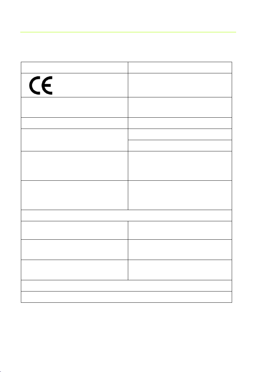
Indicator
Pursuant to EN 50081-1,
EN 50082-1, EN 61010-1 / A2
Supply voltage: 230 V AC 50 Hz
Degree of protection: IP 30 or
IP 65 acc. to IEC 529
Power input: max. 2 VA
Measuring input: 4 – 20 mA;
U0 = 20 V
Resolution: 10 Bit
Accuracy: ± 1 %
Relay output:
Switching voltage: max. 250 V AC
Switching current: max. 3.5 A
Optional (see accessories)
Analogue output: 0 - 5 V DC
4-20 mA
Dimensions W x H x D in [mm]:
120 x 120 x 49 (IP30) or
130 x 130 x 60 (IP65)
Housing: Polystyrene (IP30)
or
Polycarbonate (IP65)
Probe element (relative pressure probe for level detection)
Operating voltage: 20 V DC
Degree of protection: IP 68 acc. to
IEC529
Material: V4A ; POM;FPM; HD-PE
Length of probe (without cable)
90 mm
Standard version: 250 mbar
Length of probe connection
cable 6 m
Installation position: vertically suspended, or horizontally supine
Temperature range: Ambience operating media: 0 °C to 80 °C
Technical specification
Page 19

Security & Electronic Technologies GmbH Seite 19
Order
no.
Product description
Information on application
HW065
Data transmission
module 0-5 V
Retrofittable module as interface to
data transmission, e.g. for the
master control system of the
building
HW067
Data transmission
module 4-20 mA
Retrofittable module as interface to
data transmission, e.g. for the
master control system of the
building
HW088
M-Bus interface
For data transmission e.g. to
building control systems
HW070
PC set
Retrofit kit for data transmission to
a PC – incl. software for
indication/evaluation and for
sending messages via e-mail
HW079
Cable junction box
IP 66, water-proof, with
pressure equalization
To extend the probe cable - e.g. in
the dome
HW021
SmartBox 5 data
transmitter
GSM telecommunication system
for SmartBox 1, 2, or 3 and event
messages (e.g. burner
malfunction)
HW071
Additional antenna
Additional antenna for reception
amplification at the SmartBox 5 data transmitter
Accessories
Page 20

Wireless radio controlled filling and overfill prevention system:
LRC Small – Level Remote Control
Products for wireless data transfer in EX-zones:
SECU-DATA 420: for 4-20 mA probes
SECU-DATA 500: for 2 relay contacts
SECU-DATA 600: for NAMUR probes
SECU-DATA 710: for TRbF-probes
SECU-BAR 125: active barrier
Other products:
In the distribution line: filling level measuring systems
Visit also our homepage:
 Loading...