

Page 1

Conten
t
s Measurement
Operating Instructions
SECU-DATA-LEVEL
SD 1232L, SD 232L
SD 420L, SD 1420L, SD 421L, SD 1421L
with wireless data transmission
SDL M E 01
05 2011
Page 2

Security & Electronic Technologies GmbH
Page 2
Important: The technical specification stated in this document is subject to modification by the manufacturer without any notice.
© SECURITY & ELECTRONIC TECHNOLOGIES GmbH.
Page 3

Seite 3
Security & Electronic Technologies GmbH
TOC - Table of Contents
Safety instructions ................................................................... 4
Product description .................................................................. 4
Components..................................................................................... 4
SECU-DATA-LEVEL devices ........................................................ 5
Contents of delivery ................................................................. 6
Control elements: ..................................................................... 8
Commissioning ......................................................................... 9
Installation ........................................................................................ 9
Proper positioning of the antennae ............................................ 10
Wiring the connection lines ......................................................... 11
Terminal connection ..................................................................... 12
Adjustment of the parameters of SD (1)232L: .......................... 15
Selection of the RF channel block .............................................. 17
Operation of the equipment ................................................... 18
Maintenance ............................................................................ 21
Warranty .................................................................................. 21
Disposal................................................................................... 21
Troubleshooting ..................................................................... 22
Technical specification .......................................................... 23
Page 4

Seite 4
Security & Electronic Technologies GmbH
Safety instructions
During installation and operation of this measurement system in explosive
environments adhere strictly to the operating instructions of the manufacturer,
take into account all local applicable safety instructions, standards and technical recommendations.
SECU-DATA 420L, 421L and 232L are designed for the ATEX-zone 1.
SECU-DATA 1420L, 1421L and 1232L have to be mounted outside of ATEXzone.
For improper use and for any resulting damage, the manufacturer accepts no
liability. Changes to the product are not allowed.
Service, repair, and maintenance can be done by the manufacturer or authorised service facilities only.
The instruments shall be installed and operated by persons only who are authorized and trained by the plant operator/manager and if they have studied
and understood these operating instructions. If the devices are installed in the
ATEX-zone, the person has to be allowed and trained for installing in this
area. The operator of the plant is responsible for instructing the users.
Product description
Components
The components of the SECU-DATA-LEVEL product line make use of latest
technologies for the transmission of measurement data via radio frequency
connections in the 433 MHz band.
It is possible to use several 4-20mA measurement probes. The volume is
measured and transmitted to a PC. The program Secu-Data-Manager visualizes level information’s and generates data for possible further processing.
Page 5

Security & Electronic Technologies GmbH
Features:
• Wireless data transmission with galvanic potential free connection
• For use in ATEX-area (SD 420L, SD 421L, SD 232L)
• Class IP67 for outdoor use
• No wiring between probe and central necessary. No ground loops
possible
• Fast installation without stemming and digging
• High reliability through fail-safe wireless connection with automatic
channel selection
• Managing up to 100 tanks
• Range for local tanks up to 1500m
• Connection of far away tanks via line- or GSM-modem
Seite 5
SECU-DATA-LEVEL devices
SECU-DATA SD 1420L (non-Ex version) / SD 420L (Ex-version)
Unit for evaluation and transmission of 4-20 mA signals with 12-bit resolution
to a central receiver SD 232 or SD 1232. Further indicates a changeover relay contact, whether there is a minimum or maximum alarm.
SECU-DATA SD 1421L (non-Ex version) / SD 421L (Ex-version)
Unit for evaluation and transmission of 4-20 mA signals with 16-bit resolution
to a central receiver SD 232 or SD 1232. Further indicates a changeover relay contact, whether there is a minimum or maximum alarm.
SECU-DATA SD 1232L (nicht-Ex Version) bzw. SD 232L (Ex-Version)
Central receiver connected to a RS232 interface of a Windows-PCs or to a
modem.
SECU-Bar SB 125
Power supply and barrier to supply a SECU-DATA-LEVEL unit in hazardous
areas (SD 420, SD421, SD 232).
Page 6

Seite 6
Security & Electronic Technologies GmbH
Contents of delivery
Please, check the contents of delivery immediately after receipt and unpacking. In case of missing components or transport damages contact your local
dealer or a SECU-TECH representative.
You need for each tank or probe one measurement device (SD 1420L, SD
1421L, SD 420L or SD 421L). For connection to a PC you need one SD
1232L or SD 232L. For each device you need an aerial stick. For each device
in the hazardous area you need one barrier SB 125.
SD 1420L – 4-20 mA, 12-Bit resolution (non-ATEX)
• For small tanks or if a lower resolution is acceptable
Order No. ST002033
SD 1421L – 4-20 mA, 16-Bit resolution (non-ATEX)
• For big tanks, very precise resolution Order No. ST002031
SD 420L – 4-20 mA, 12-Bit resolution (ATEX)
• For small tanks or if a lower resolution is acceptable
Order No. ST002034
SD 421L – 4-20 mA, 16-Bit resolution (ATEX)
• For big tanks, very precise resolution Order No. ST002035
SD 1232L Receiver (non-ATEX)
• For connection to PC or modem
Order No. ST002032
SD 232L Receiver (ATEX)
• For connection to PC or modem on request
SB 125 – Barrier and power supply for ATEX devices
• 24VDC active barrier Order No. ST002020
Aerials:
Secu-Top150 Standard, lambda/4 aerial ST002027
Secu-Top300 for more range, lambda/2 aerial ST002025
Secu-Roof 150 car roof aerial with 4m cable ST002030
Page 7

Security & Electronic Technologies GmbH
Optional Accessories:
SITOP-POWER 230VAC to 24VDC power supply for DIN rail ST002027
SECU-TOP1 aerial cable extension 1 m + angle ST002021
SECU-TOP3 aerial cable extension 3 m + angle ST002022
SECU-TOP6 aerial cable extension 6 m + angle ST002023
Trafag 8438 hydrostatic probe 250mbar, 0,2% HW009001
More level measuring probes on request!
Furthermore, you need:
• Connection cable RS232 to PC
• Possibly a USB / RS232 adapter
• Level probe (e.g. look at optional accessories) with 4-20mA output (if
your probe is not supported by Secu-Data-Manager program, please
send a request with the probe data sheet to our development department: ms@secu-tech.at
• For hydrostatic probes you need additionally:
o Pressure compensation box
o Protective tube
• PC with Windows XP, Vista or Windows 7
• Possibly a line- or GSM-modem with RS232 interface
Seite 7
Page 8

Seite 8
LED
wire
Security & Electronic Technologies GmbH
Control elements:
LED indicators with the following functions
Green: Radio connection:
Off: no RF connection
Blinking: searching for partner device,
On: RF connection active
Yellow: Power supply:
Offl: power failure
On: power supply in nominal range
Blinking : programming mode or modem reset
Red: Error indication:
Off: system working properly
On: internal error or device was initialized (blinking)
RF aerial: app. 150 mm (λ/4), with TNC connector. Extension cables and
an extra long antenna (λ/2) are available as an option.
Cable glands (M16 x 1.5).
glands
Aerial
indicators
Page 9
Security & Electronic Technologies GmbH
Seite 9
Commissioning
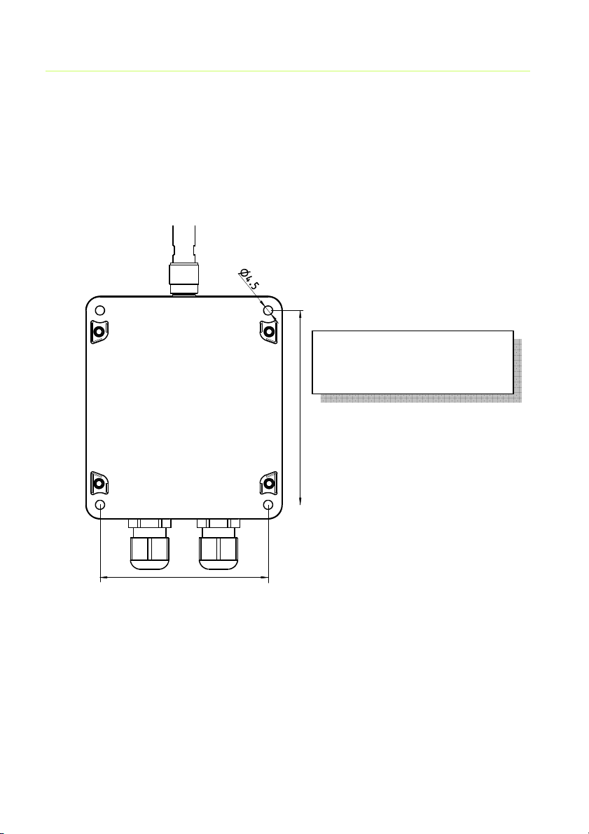
Installation
Mount the SECU-DATA-LEVEL (without power) to a base with 4 pieces M4screws:
M4
Distance of drilling holes:
Horizontal: 83 mm
Vertical: 96 mm
96 mm
83 mm
In case of metallic base material (chassis of vehicles, machinery) try to maximize the distance between RF-antenna and the base to achieve maximum
effective RF range.
Mount the RF-antenna or the extension cable to the connector on the housing.
The devices have internal block terminals (type: WAGO series 256, ATEX
certified) for connection of the corresponding external wires.
Page 10

Seite 10
wall
Antenna free
Antenna free
wall
wall
Security & Electronic Technologies GmbH
Attention:
Only qualified personnel with relevant training and authorization by the system operator may SECU-DATA connect to an existing plant. The locally applicable safety regulations must be observed.
Proper positioning of the antennae
Right:
Metal or
Wrong!
Metal or
Mount the antenna as
high as possible to give
radio a chance to over-
come buildings
Antenna is
shielded
Metal or
Page 11

Security & Electronic Technologies GmbH
Seite 11
Wiring the connection lines
Open the housing by removing the fixing screws of the lid.
Button A
Important:
Install the wiring only after the power supply of the installation has been
turned off.
Follow strictly the safety instructions from the manufacturer; adhere to all applicable standards, norms and technical guidelines.
Pass all required wires through the cable glands (M16 x 1.5) and fix them
tightly to ensure the water protection of the housing. You can use one or both.
If you let one of them unused, mount the dummy plug to seal it.
Button B
Page 12

Seite 12
Security & Electronic Technologies GmbH
Terminal connection
SD 1420L, SD 1421L, SD 420L, SD 421L
Terminal Signal, Description
1
Plus of power supply (+11 V …+40 V),
reverse polarity protected over 2 diodes
2
Minus of power supply (0 V)
3
Measurement signal 4-20 mA, plus to supply
passive probes 4-20mA (for active probes don’t
connect this pin)
4
Measurement signal 4-20 mA (minus for passive probes)
5
Minus for active probes 4-20mA (Attention:
standard until 2012, when ordering please specify in advance)
(for passive probes 4-20mA don‘ connect this
pin)
6, 7, 8
Relay contact to signal the Min- or Max-Alarm
7 is the common, on alarm terminal 6-7 are
closed, for no alarm 7-8 are closed.
Maximum load: 30 V, 500 mA !
Page 13

Security & Electronic Technologies GmbH
Pro
tective tube
SD 142xL, SD 42xL with passive 4-20mA probe:
Pressure compensation box
+24VDC, e.g. from SB 125
Minus
Protective tube
probe +
Tank
Probe output
+24VDC
Relay, 24VDC, <500mA
Minus
probe
SD 142xL, SD 42xL with active 4-20mA probe:
Attention: first 2012 in series previously specify when ordering!
Pressure compensation box
+24VDC, e.g. from SB 125
Minus
Probe output
Tank
+24VDC
probe -
Relay, 24VDC, <500mA
Minus
1
2
3
4
5
6
7
8
1
2
3
4
5
6
7
8
Seite 13
Power supply
4-20mA
Alarm-contact
Power supply
4-20mA
Alarm-contact
probe
Page 14

Seite 14
Security & Electronic Technologies GmbH
SD 1232L, SD 232L
Terminal Signal, Description
1
Plus of power supply (+11 V …+40 V),
reverse polarity protected over 2 diodes
2
Minus of power supply (0 V)
3
TxD, data-output to PC or modem
4
RxD, data-input from PC or modem
5
RTS, handshake-output to PC or modem
6
CTS, handshake-input from PC or modem
7
Minus of RS232, minus for modem power
supply
8
Switched +24VDC power supply for modem
SD 1232L, SD 232L on PC:
9
8
7
6
9-pin D-Sub socket
+24VDC, e.g. from SB 125
5
4
3
2
1
Minus
1
2
3
4
5
6
7
8
Power supply
TxD
RxD
RTS
CTS
Minus
Page 15

Security & Electronic Technologies GmbH
Seite 15
SD 1232L, SD 232L on modem:
9-pin D-Sub
plug
6
7
8
9
+24VDC power supply for modem
+24VDC, e.g. from SB 125
1
2
3
4
5
Minus for modem
Minus
1
2
3
4
5
6
7
8
Power supply
TxD
RxD
RTS
CTS
Minus
Supply your 24VDC modem over Pin 7 and 8 (Attention: power consumption<= 500mA). In this case the SD (1)232L can automatically switch the
power of the modem and initialize it accordingly, e.g. if it comes to a crash of
the modem.
Adjustment of the parameters of SD (1)232L:
If you only want to connect the SD (1)232L central to the PC, it is not necessary to adjust the parameters, cause the default values are set to PC use.
Do you want to connect the SD (1)232L to a modem, you have to adjust the
parameters.
Connect the device to a PC (as indicated on page 14) and leave open the lid.
Start a terminal program (e.g. HyperTerminal) and set the parameters of the
program to 9600 baud, 8 data bits, 1 stop bit, no parity, hardware handshake
or no handshake. Furthermore, you should enable the local echo to see your
entries.
Page 16

Seite 16
Security & Electronic Technologies GmbH
Press and hold the button „A“ and press the button „B“ two times. Now you
can release the button „A“.
On the terminal screen is displayed:
Baudrate >> 0:1200 1:2400 2:4800 3:9600 4:19200 5:38400 6:76800 7:115200 8:300 9
:600?
[5]:
Do you want to connect the device directly to a PC, press 5 (or Enter, if the
number is shown in the right bracket): 5 = 38400 Baud
Do you want to connect it on a modem, then press 7 (115200 Baud).
PC: „5“ (38400 Baud)
Modem: „7“ (115200 Baud)
Parity >> 0:NO, 1:EVEN, 2:ODD ?
[0]:
PC: „0“ (no parity)
Modem: “0“ (no parity)
Databits >> 0:7_BIT, 1:8_BIT ?
[1]:
PC: “1” (8 data bits)
Modem: “1” (8 data bits)
Stopbits >> 0:1_BIT, 1:2_BIT ?
[0]:
PC: „0“ (1 stop bit)
Modem: „0“ (1 stop bit)
Mode >> 0:RS232, 1:GSM_Modem ?
[0]:
PC: „0“ (RS232 -> PC connection)
Modem: „1“ (modem connection)
Then it will displayed OK and the device is configured.
Page 17

Security & Electronic Technologies GmbH
Taste B
Taste A
Example for modem configuration:
Seite 17
Selection of the RF channel block
SECU-DATA-LEVEL device use one RF-channel out of 64. These are organized in 8 blocks with 8 channels each. Within this frequency block the SD
(1)232L is searching a unused channel. The default setting is block #6. Each
SECU-DATA-LEVEL devices of a system have to have the same frequency
block.
Vorgangsweise für alle Geräte:
Page 18

Seite 18
Security & Electronic Technologies GmbH
Open the housing. Avoid the intrusion of moisture and pollution while the instrument is open to maintain the reliability!
1. Turn on the power supply of the device
2. Press the B-button two times shortly
3. The green RF-LED will blink several times, the number of light pulses
gives the actual number of frequency block (1-8).
4. The light pulses are repeated after a 1 s pause. Each press on button
A increments the block number by 1. On the end of the range the
block number falls back from 8 to 1 automatically.
5. An interruption of the power supply aborts the procedure, the original
block number remains in memory; the actual one is not stored.
6. The procedure can be finished by pressing the B-button; the actual
block number is stored permanently.
7. Repeat this procedure for the next device to set the same block
number.
If required you may check the block number using steps 1 to 4 as described
above..
Operation of the equipment
The devices SD 420L, SD 421L, SD 1420L and SD1421L supplies the passive 4-20mA probe and permanently measure the current signal with high accuracy and resolution (12- or 16-bit).
The central SD 1232L or SD 232L receives directly from the PC (over RS232)
or over a modem commands to request a SD (1)42xL and sent the values of
alarms to it.
The SD (1)232L sends this information to the requested device and gets the
digital measured current value back.
Both alarm levels will stored permanently in the SD (1)42xL, so the alarm relay is working also if the radio link is broken (e.g. the PC is shut down).
The SD (1)232L sends the received mA values to the PC. The PC calculates
the volume and the level of the tank .
Page 19

Security & Electronic Technologies GmbH
If you are working with a hydrostatic probe, the displayed volume is independent from temperature. However, the displayed liquid level is only valid at the
same temperature at which the tank table was created. This is usually 15 ° C.
The system is basically limited only by the software to 100 tanks. For local
tanks (directly controlled by radio from the PC), the tanks are permanently
polled (about 4 tanks per second). If you have installed 100 local tanks, the
update rate is about 25 seconds, at 4 local tanks, 1 second.
Far away tanks can be joined to islands via modem. I.e. one SD (1)232L on a
far away tank farm can theoretically control up to 100 tanks there.
The PC-Program can theoretically control up to 100 far away tank farms.
The limit of the system is to have at maximum 100 tanks in one system. If
you need more tanks, a special software can be developed.
Limit examples: You can define 100 different far away tank farms, each of
them with one tank. Also you can define one far away tank farm with 100
tanks.
The modem connection is established depending on the setting once a day
or once per hour. This is not a SMS or GPRS technology, but a normal call
set-up with data exchange.
In this case you have only costs for the call on the central (on the PC side)
and not on the remote tank farms, because the central will call the other stations.
In principle, every line modem or GSM modem can be used with AT command set. To ensure reliable operation, we recommend the use of industrial
grade modems.
Seite 19
Page 20

Seite 20
Security & Electronic Technologies GmbH
Example of a system with local and 2 remote tank farms tanks:
Local
SD 421 SD 421
SD 420
SD 421
SD 420
SD 1232
Computer
Modem
London Paris
SD 1420
SD 1421
Modem
SD 1232 SD 1232
Modem
Page 21

Security & Electronic Technologies GmbH
Seite 21
Maintenance
Devices of the product range SECU-DATA-LEVEL do not need any maintenance, no user serviceable components are inside of the housing.
Important:
Repair and service tasks can be done by qualified service personnel only.
This is the only way to maintain the required level of ignition prevention.
Warranty
For the actual services and conditions see the internet home page:
www.secu-tech.at see the GTCS – General Terms and Conditions of Sale.
Disposal
SECU-DATA instruments must not be
disposed of via the municipal waste collection system.
Security & Electronic Technologies
GmbH. takes back used SECU-DATA instruments for appropriate disposal for a
small charge.
The symbol for disposal via qualified recyclers is attached visibly and permanently on the instrument.
Page 22

Seite 22
Security & Electronic Technologies GmbH
Troubleshooting
Problem: The radio connection cannot be established
Solution 1:
Check:
• Is the supplied antenna mounted correctly?
• Are there obstacles which block the propagation of the RF waves?
• Is the distance between transmitter and receiver more than 1 km
(with standard antenna)?
Select an optimal position for the antenna, antenna extension cables are
available as an option.
Solution 2:
Interrupt shortly the power supply of the affected devices and turn them on
again. The modules will establish a new connection and they will search for
free undistorted RF-channels automatically.
Solution 3:
Restart your PC and the Secu-Data-Manager program.
Solution 4:
Check the number of frequency block. All devices have to have the same
block to can communicate together.
For the procedure of verification and re-definition of the RF-channel block see
chapter „Selection of the RF channel block“
Solution 5:
Check the parameters of the RS232.
For the procedure of verification and re-definition of the parameters see
chapter „Adjustment of the parameters of SD (1)232L“
If all measures described in this chapter do not solve your problem then send
in the modules with a short description of the problem and with a copy of the
delivery note (in case of warranty claims) to the manufacturer or to an authorised service facility.
Page 23

Security & Electronic Technologies GmbH
Seite 23
Technical specification
Funkdatenübertragung:
The radio data exchange is bidirectional and works in the 433MHz band. It is
a very narrow band radio with 25kHz band space, 64 channels divided in 8
blocks to 8 channels (block number is changeable on the device). Radio
range: 1 km on free space (more with 30cm antenna stick), high temperature
stability, immune to interference, automatic selection of an undisturbed channel. Hardware data speed between Secu-Data devices: 4.800 Baud .
Technical specification - general
Display:
Fuses:
RF module:
Housing
Dimensions (L x W x H): 146 x97 x60 mm (Without antenna and cable glands)
Weight: app. 650 g incl. antenna
Antenna: app.160 mm, connector: TNC
Construction: moldered
Protection: IP 67
CTI value: 250 (SD 420L, SD 421L, SD 232L)
3 LEDs
Thermo fuse
Conform to ETSI EN 300 220
Rated specification
Supply voltage: 11 V ... 40 V DC,
Power consumption (without probe): max. 1,2 W
Ambient temperature: -30°C ≤ Ta ≤ ... +75°C
Measurement uncertainly SD 421L, SD 1421L - 16-Bit
Typical at 25°C: ±0,02% of measured value
Max. (-30 … 75°C): ±0,1% of measured value
Resolution : 0,4 µA
Rise time: <0,5 s
Messunsicherheit SD 420L, SD 1420L - 12-Bit
Typisch bei 25°C: ±0,1% of measured value
Max. (-30 … 75°C): ±0,3% of measured value
Resolution: 6 µA
Rise time: <0,5 s
Page 24

Seite 24
Security & Electronic Technologies GmbH
ATEX parameters – for SD 232L, SD 420L, SD 421L:
Attention: For applications in explosive areas all inputs have to be
connected to intrinsically safe lines only.
Power supply (Pins 1, 2, ignition protection „ib“):
UI = 25,2 V, II = 131,3 mA, CI ~ 0, LI ~ 0
Alarm relay (Pins 6, 7, 8, ignition protection „ib“):
UI = 30 V, II = 500 mA, CI ~ 0, LI ~ 0
SD 420L, SD 421L – current input (Pins 3, 4, ignition protection „ia“):
UO = 25,2 V, IO = 146,8 mA, CO = 107 nF, LO = 2 mH
SD 232L
Ignition protection: “ib”, against terminal 7:
Terminal 3 (TxD): U0 = ±10 V, I0 = 12 mA, C0 = 3 μF, L0 = 2 mH
Terminal 4 (RxD): Ui = ±15 V, Ii = 50 mA, Ci = ~0, Li = ~0
Terminal 5 (RTS): U0 = ±10 V, I0 = 12 mA, C0 = 3 μF, L0 = 2 mH
Terminal 6 (CTS): Ui = ±15 V, Ii = 50 mA, Ci = ~0, Li = ~0
Terminal 8 (modem power): U0 = 25,2 V, I0 = 146,8 mA, C0 = 107 nF, L0 = 2
mH
Norms, standards applied:
ATEX (EC directive 94/9/EC), EN 60079-0:2004, EN 60079-11:2007, EN
61241-0:2006, EN 61241-11:2006, EN 60529, ETSI EN 300 220 (EC
directive 5/1999 R&TTE).
ATEX certification
SD 232L, SD 420L, SD 421L:
Certification No.: TÜV-A 06ATEX0008X
Class: II 2 G Ex i(a)b IIC T4
II 2 D Ex i(a)bD (20)21 T135°C
SECU-BAR 125:
Certification No.: TÜV-A 06ATEX0009X
Class:
II (2) G [Ex i(a)b] IIC T4
II (2) D [Ex i(a)bD] (20)21 T135°C
 Loading...