

Page 1
Securitron Magnalock Corp. www.securitron.com ASSA ABLOY, the global leader
T
Tel 800.624.5625 techsupport@securitron.com
in door opening solutions
ELECTRO-MECHANICAL BAR (EMB) SERIES
INSTALLATION INSTRUCTIONS
1. SPECIFICATIONS
MECHANICAL ELECTRICAL/ENVIRONMENTAL
Physical Size:
Height: 2-5/8” [66mm]
Depth: 1-5/8” [41mm] (from mounting
surface)
Overall Length:
36” Door = 34-1/2” [876mm]
42” Door = 40-1/2” [1029mm]
48” Door = 46-1/2” [1181mm]
Operating Force (Maximum): 15 Lbs. [66.7N]
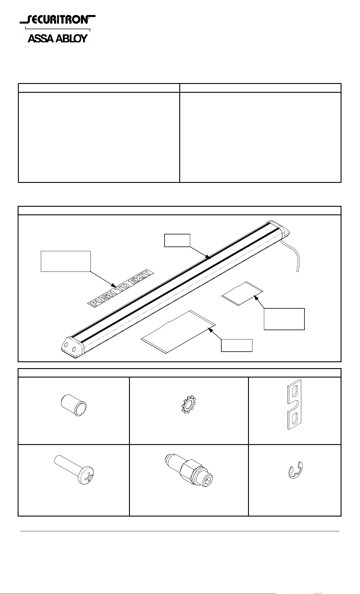
2. COMPONENTS
EMB UNIT PACKAGE
Push To Exit
Label
Maximum Recommended Current:
1.5 Amps @ 30VDC
Environmental (Recommended):
Temperature: 32ºF to 120ºF [0ºC to 49ºC]
Humidity: 10% to 90% RH
EMB
Mounting
Hardware
SB-C
MOUNTING HARDWARE
4X – 1/4-20 Blind Nut 4X – External Tooth Washer 2X – End Mount Retainer
4X – 1/4-20 x 1” Long
Phillips Pan Head
1X – Blind Nut Installation Tool 2X – E-clip
© Copyright, 2011, all rights reserved PN# 500-23130
Page 1 Rev. C, 03/11
Page 2
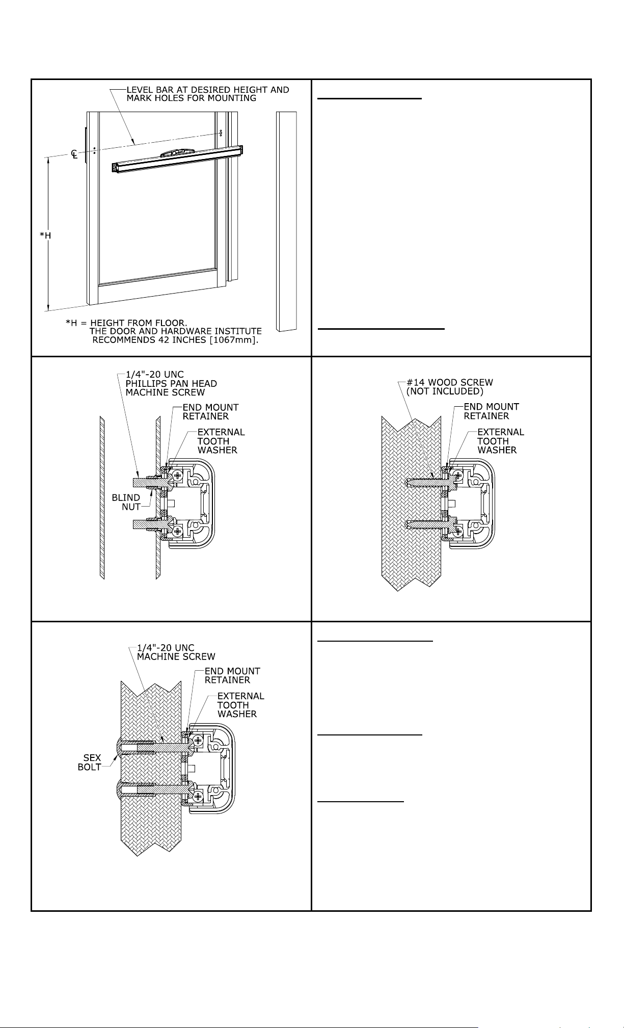
3. DOOR PREPARATION
New Installation:
With the door in the closed position, verify
that the bar fits between the stops of the
door frame. If not, the bar may be
shortened as described in Section 6.
Review the following illustrations and
determine the mounting configuration to be
used (i.e. hollow metal, solid wood or
through door).
Using a Phillips screwdriver, remove the bar
end caps.
Position and level bar against inside of door
between frame stops.
Using the holes in the bar end mounts
and/or the Mounting Diagram, mark hole
locations for mounting.
Replacement Install
:
Remove existing bar and hardware.
Hollow Metal Door (Blind Nut) Solid Wood Door (Screw)
Hollow Metal Door
:
Drill holes through mounting surface only as
shown in the following Mounting Diagram
(Detail A and B).
Install blind nuts as described in the Blind
Nut Installation section.
Solid Wood Door
:
From the mounting surface drill four (4)
7/32” [5.5mm] diameter holes to the depth
of the #14 screws to be used.
Through Door
:
The through door mount configuration requires
the EMB-TDM accessory kit. This kit, which
may be ordered separately, provides a secure
through-the-door attachment of the EMB to
various door types. Please follow the
Through Door Mount
(Requires EMB-TDM Kit)
PN# 500-23130
Page 2 Rev. C, 03/11
instructions included with the EMB-TDM kit for
proper installation.
Page 3
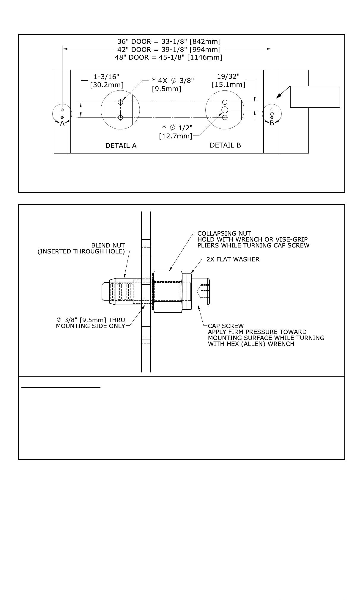
Hinge Side
of Door
Mounting Diagram
Hollow Metal (Aluminum Frame Glass) Door Preparation Shown
* NOTE: Drill holes through mounting side of hollow doors only!
Blind Nut Installation:
Insert the blind nut of the installation tool into a 3/8” [9.5mm] diameter hole.
Hold the collapsing nut with a 1/2” box end wrench.
While maintaining pressure toward the mounting surface, use a 3/16” hex wrench to tighten
the cap screw and collapse the blind nut.
Once the blind nut is firmly collapsed, remove the to ol by unthreading the cap screw from the
installed nut.
Place another blind nut onto the installation tool and install remaining blind nuts using the
same procedure.
PN# 500-23130
Page 3 Rev. C, 03/11
Page 4

4. INSTALLATION
Mount Bar to Door
:
Feed wire cable through hole in
door, or route wire through the
end cap (See Wire Routing
instructions in Section 5).
Install bar to door (Detail C)
using included hardware – or
the hardware from previous bar
installation.
Ensure that the end mount
retainer is used to provide
secure attachment to door.
Connect electrical circuit(s) and
test operation (See Section 7 for
general wiring diagrams).
Install bar end caps and the
push to exit label.
5. WIRE ROUTING
Routing the EMB wire cable from a solid wood door to the frame can optimally be acco mplished
utilizing a concealed electrical power transfer device (such as Securitron’s EPT, EPTL, CEPT or
SEPT). Another alternative for solid or glass door mounting of the EMB is routing the wir e cable
through the bar’s end cap. See Wire Routing Through End Cap, Section 5.1 for detailed
instructions on implementing this option.
Routing the wire from a hollow metal door to the frame may be achieved using the included
TSB-C armored door cord. The TSB-C is normally installed toward the top and along the hinge
side of the door. The following step-by-step instructions may be used to install the TSB-C:
TSB-C Installation:
Drill a 3/8” [9.5mm] diameter hole in both the door and frame as shown.
Position door cord caps to fully cover each of the 3/8” [9.5m m] diameter holes, and then mark
the two (2) mounting holes for each cap.
Drill a 1/8” [3.2mm] diameter hole at each of the previously marked cap mounting hole
locations.
Insert one door cord insert into each end of the flexible door cord shield.
Run wire cable from the hole in the door through the door cord shield (with inserts).
Route wire cable through hole in frame and make electrical connections.
Insert each end of the door cord shield into one of the cord caps. Ensure that the spiral
grooves of the cord shield are engaged by the teeth inside the cord cap.
Install the two (2) cord caps, one to the door and one to the frame, using the provided #6
screws.
PN# 500-23130
Page 4 Rev. C, 03/11
Page 5

5.1 WIRE ROUTING THROUGH END CAP (OPTIONAL)
OR
Left End Cap
(Bottom)
Right End Cap
(Bottom)
Drill End Cap:
Determine which bar end cap to
feed the flexible door cord shield
into. Normally the bar wire cable
and door cord shield go to the
hinge side of door.
Mark and/or center punch the
bottom side of the chosen end
cap at the location shown.
Drill a 3/8” [9.5mm] diameter
hole through the wall of the end
cap.
Install Cord Shield to Cap
:
Insert the door cord shield
through the hole drilled in the
end cap.
Secure cord shield in place
through the hole using two (2)
provided E-clips. (One to the
inside and one to the outside of
the cap).
Install Door
Cord Insert
Here
Install a door cord insert into
each end of the door cord shield.
Route bar wire cable through the
cord shield.
Install the end cap to the end of
the bar.
3/8” [9.5]
Diameter Hole
2X 1/8” [3.2]
2X #6 Mounting
Diameter Hole
Screws
Door Cord
Door Cord
Insert
Cap
Install Cord Shield to Frame:
Drill a 3/8” [9.5mm] diameter hole into the door frame at the desired position adjacent to bar
end mount.
Position door cord cap to fully cover the 3/8” [9.5mm] diameter hole, and then ma rk the two
(2) mounting holes.
Drill two (2) 1/8” [3.2mm] holes at the marked locations.
Install door cord insert over end of bar wire cable and slide up and into the loose end of the
flexible door cord shield.
Route wire cable through hole in frame and make electrical connections.
Insert the end of the door cord shield into the cord cap. Ensure that the spira l grooves of the
cord shield are engaged by the teeth inside the cord cap.
Install the door cord cap over the wire cable and door cord shield, and then secure into place
using the two (2) provided #6 screws.
PN# 500-23130
Page 5 Rev. C, 03/11
Page 6

6. SHORTENING THE BAR (OPTIONAL)
Measure for fit:
Measure the distance between stops on the door frame.
Subtract 2” [51mm] from the distance measured between stops. This will be the
measurement to use to cut both of the aluminum bar extrusions.
o Example: The distance between stops is 31-3/4 inches [806mm], subtract 2 inches
[51mm] = total extrusion length of 29-3/4 inches [755mm].
Remove both of the end caps from the front bar extrusion and remove the end m ount located
opposite the wire cable end of the bar from the rear bar extrusion.
Cut to size:
Slide the front bar extrusion completely off of the bar assembly and mark required length.
Using a chop or miter saw, cut the front bar extrusion to length.
Using same measurement, mark the length for the rear bar at the end of the extrusion
opposite the wire cable end.
Using a chop or miter saw, cut the marked end (opposite the wire cable) to length.
Using compressed air clean all debris from cutting operations out of the inside of the bar.
PN# 500-23130
Page 6 Rev. C, 03/11
Page 7

7. ELECTRICAL CONNECTION
Typical Wiring Configurations:
The following wiring diagrams are provided as examples of various egress control configurations.
Single Magnetic Lock:
Note:
Each wiring diagram shows an MOV wired in parallel with the magnetic lock. An MOV acts to
suppress the inductive kickback generated by a lock which, if left unsuppressed, could greatly
shorten the life of the bar’s switch contacts. The MOV has no polarity, but in order to function
properly it should be spliced into the wiring as close to the lock as possible. An MOV is provided
with each EMB unit.
If a Securitron Magnalock is used in an installation, the implementation of an MOV is
NOT necessary as the Magnalock is already internally suppressed.
Double-Door/Dual Magnetic Locks:
PN# 500-23130
Page 7 Rev. C, 03/11
Page 8

Double Break Wiring
Many installations include a controlled access device such as a digital keypad or card reader.
Such devices typically have a REX (request to exit) input. When dry contacts close on this input,
the entry device will open the lock for the same amount of time that is programmed for entry.
Implementation of the REX input for exit can provide timed exiting. Also, for most entry
controls, the REX input must be use d fo r exiting to avoid an alarm condition at the door.
If the REX input alone is used for exiting, a safety/reliability problem will exist. If the entry
device malfunctions, exit will not be possible and people may be trapped. It is recommended
that double break wiring which is supported by the EMB be used. The EMB normally closed
contacts are used to break power to the fail safe electric lock while the normally open contacts
trip the REX input of the controlled entry device. This releases the lock a second time, hence the
term, "double break". If the controlled entry device fails for any reason, direct exit is still
possible.
The following diagram illustrates a typical double break wiring circuit.
Double Break Wiring:
ELECTRO-MECHANICAL BAR USAGE NOTES
:
As the EMB is normally used to permit egress on an electrically secured door, ensure
that all applicable building and fire codes are being followed. Verify installation with
local building and/or fire prevention codes and regulations.
The EMB may not be used on a fire rated door that requires a fire rated latch! The EMB
has no latch. In some instances however, fire doors are permitted on openings where
a fire rated barrier is not required. Use of the EMB should always be verified and
approved through local building code and/or fire prevention agencies.
IF YOU ENCOUNTER PROBLEMS WITH THE INSTALLATION OF THIS PRODUCT,
CALL SECURITRON: 1-800-MAG-LOCK
8. MAGNACARE
LIFETIME REPLACEMENT WARRANTY
For warranty information visit: www.securitron.com/en/site/securitron/About/MagnaCare-Warranty
PN# 500-23130
Page 8 Rev. C, 03/11
 Loading...