

Page 1

Model TSH
Touch Sense Handle
Installation and
Operation Instructions
1 500-17700, Rev D
Page 2

Table of Contents
Description ................................................................................................ 3
UL 294 Access Control Performance Levels ............................................ 3
Installing the TSH ...................................................................................... 3
RemovetheHandle...............................................................................3
DrilltheMountingandWireWayHoles...............................................4
MountthePlasticBasetotheDoor......................................................5
ConnecttheElectricalWithinthePlasticBase.....................................5
MounttheHandletothePlasticBase..................................................6
ConnecttheElectricalWiringandPowerSupply..................................6
Adjust
andTesttheSensitivity..............................................................8
TestandUsetheRedundant(Backup)Switch....................................10
InstallthePlaque................................................................................10
SelecttheElectricLock........................................................................10
ReplacetheSensor..............................................................................11
Operational Security Considerations ...................................................... 11
Troubleshooting ...................................................................................... 12
MagnaCare® Lifetime Replacement Warranty ........................................ 14
2 500-17700, Rev D
Page 3

Description
The Model TSH touch sense handle is an exit device for doors secured
by electric locks. It can be employed as a door push or pull and is
particularly well suited for aluminum frame glass doors. The assembly
consists of a plastic base with an electronic touch sensor mounted
inside, and an aluminum handle which is used to pull or push the door
open. Touching the handle trips a relay in the sensor, releasing the lock.
The relay contacts are double pole with the second pole being optionally
employed to shunt either an alarm system or the alarm function of an
access control system. The unit’s sensitivity is adjustable. In the
unlikely event of sensor failure, a push switch is mounted on the plastic
base. Depressing the switch has the same effect as activating the
sensor by touch and therefore represents built in safety redundancy.
The TSH cannot be used outside in rain conditions.
As the TSH is normally used to allow egress on an electrically secured
door, make sure that you are complying with applicable building codes
for your area. Check with your local building department and/or fire
prevention department.
UL 294 Access Control Performance Levels
The following are the UL294 access control performance levels:
Destructive Attack = Level 1
Line Security = Level 1
Endurance = Level IV
Standby Power = Level 1
Installing the TSH
Remove the Handle
1. UNSCREW the handle from the plastic base (large Phillips screws) to
reveal the base mounting holes.
2. SET the handle aside.
3 500-17700, Rev D
Page 4

Drill the Mounting and Wire Way Holes
NOTE 1: There are two different diameters of holes depending on the
door type. Hollow metal doors employ supplied machine
screws and "blind nut" fasteners. The second method is to use
wood screws (not supplied) on a solid wood door.
NOTE 2: If the TSH is used on a solid door, the door must be core
drilled to get the wire way cable to the hinge side for take-off
via the supplied door cord.
NOTE 3: The TSH may not be used on a fire-rated door that requires a
fire-rated latch (the TSH has no latch).
1. USE the supplied template to set drilling positions for the two
mounting holes.
2. For a hollow metal door, DRILL two 3/8" [9.5 mm] diameter
holes only deep enough to get
not completely through the door.
NOTE: The TSH may be mounted with wood screws (not furnished).
It is recommended that 1-3/4" #14 wood screws with a hex,
pan, oval, or round head be used for mounting.
3. For a solid wood door, DRILL two 3/16"
to a depth of 1-1/4" (32 mm).
through the inner side of the door—
(5 mm) diameter holes
NOTE 1: The TSH connects to its power source and to the devices it
controls using a six-conductor cable with push-on connector
(supplied).
NOTE 2: Exit from the door may be via the supplied door cord, which
may be mounted at the top of the door, where it is out of the
way, or via any of many commercially available transfer hinges
or pivots, which serve to route the wiring off the door in a
concealed manner.
NOTE 3: The template for the wire way hole is handed. The TSH can
be vertically flipped to suit a right hand or left hand door, but it
must be known which way the aluminum handle will face in
order to correctly orient the template.
4. DRILL a 3/8" [9.5 mm] diameter hole for the wire way.
4 500-17700, Rev D
Page 5
Mount the Plastic Base to the Door
1. PERFORM the following to mount the plastic base to a hollow metal
door.
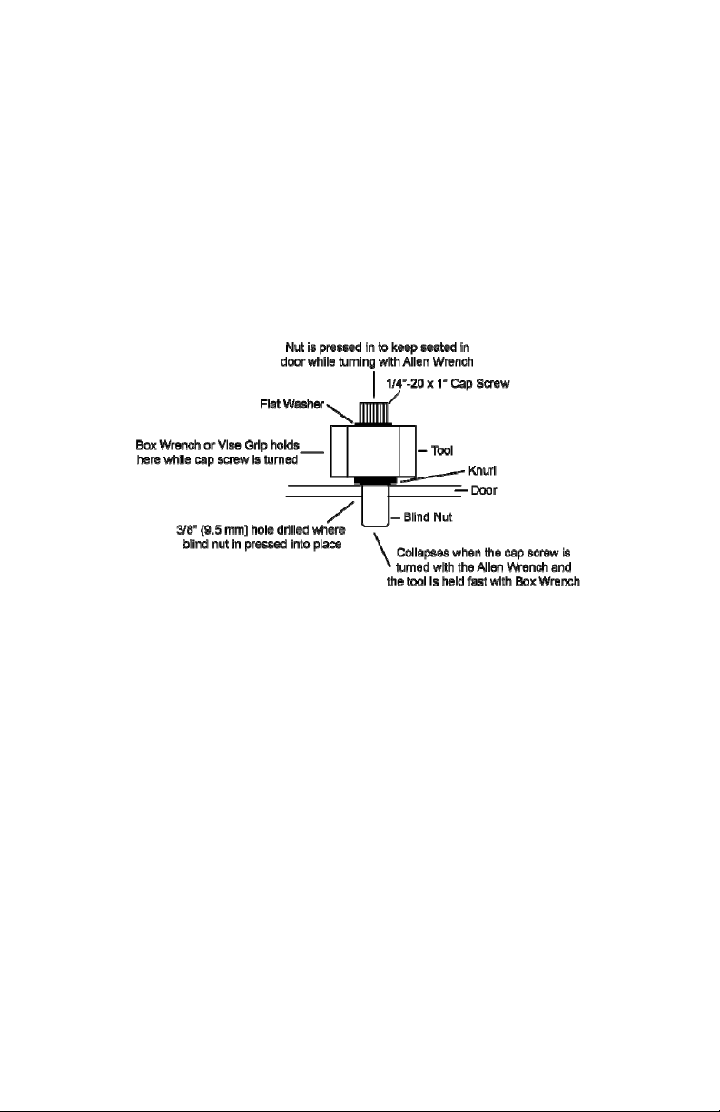
a. LOCATE the two supplied blind nuts.
b. INSERT the nuts with the knurl engaging the edge of each hole.
c. USE the supplied collapsing tool to collapse the nuts (see
Figure 1, “Collapsing the Blind Nuts in a Metal Door”).
d. PLACE a tooth washer under the head of each screw and
MOUNT the plastic base.
e. TIGHTEN the cap screw, but DO NOT OVERTIGHTEN.
Figure 1. Collapsing the Blind Nuts in a Metal Door
Connect the Electrical Within the Plastic Base
NOTE: Electrical connections with the plastic base must be made
before the handle is attached to the base.
1. ROUTE the cable connector across the circuit board and PLUG into
the corresponding connector on the board (see Figure 2, “Plastic
Base and Handle Detail”).
5 500-17700, Rev D
Page 6

Figure 2. Plastic Base and Handle Detail
Mount the Handle to the Plastic Base
1. INSTALL the handle onto the base using the two large flathead
Phillips screws.
Connect the Electrical Wiring and Power Supply
NOTE 1: Figure 3, “TSH Wiring for Fail Safe Electric Lock,” and
Figure 4, “TSH Double Break Wiring,” show a generic use of
the TSH with any type magnetic lock and power supply.
NOTE 2: When using all Securitron products, the installation is simple.
It should be noted that for any Securitron Magnalock, the red
wire denotes the "+" input and the black wire denotes the “–“
input. Also, the MOV does not need to be installed with any
Securitron Magnalock.
1. CONNECT the electrical wiring in accordance with Table 1, “Sensor
Wiring,” and Figures 3 and 4.
6 500-17700, Rev D
Page 7

Table 1. Sensor Wiring
r
Wire Colo
Red “+” DC Power
Black “–“ DC Power
White Relay Common, Pole 1
Green Relay Normally Closed, Pole 1
Blue Relay Common, Pole 2
Orange Relay Normally Closed, Pole 2
Connection
Figure 3. TSH Wiring for Fail Safe Electric Lock
Figure 4. TSH Double Break Wiring
2. CONNECT the power supply outputs to the rest of the system as
shown above.
7 500-17700, Rev D
Page 8

Adjust and Test the Sensitivity
NOTE: The TSH is capable of being operated by a wide variety of
power supplies and does not require regulated power.
However, a certain class of power supplies called "switching"
can sometimes interfere with operation. Switching power
supplies can produce line noise which affects the TSH by
rendering it hard to adjust.
1. PERFORM the following if the TSH is hard to adjust.
a. REPLACE the power supply with a linear power supply, if
possible.
b. IF not,
THEN CONNECT one 0.01 mF capacitor between power supply
“+” and earth ground, and CONNECT a second 0.01 mF
capacitor between power supply “–“ and earth ground (see
Figure 5, “Connecting Capacitors to a Switching Power Supply.”
Figure 5. Connecting Capacitors to a Switching Power Supply
2. PERFORM the following test to make sure a problem does not exist
after the installation is complete.
a. TURN UP the sensitivity up to the point just before it is open all
the time.
NOTE: The effect of coupling the reader's energy though a body
into the door tends to increase the sensitivity of the TSH.
b. From the outside of the door, PLACE hand on the reader and
LEAN body against the door to see if the TSH can be triggered.
8 500-17700, Rev D
Page 9

NOTE 1: Securitron has developed a simple filter circuit which will
absorb the interference from the reader. This requires a
22 millihenry (mH) inductor (DigiKey Part # M7223-ND, JW
Miller Part # 70F222AI). This part can also be purchased
at a local electronics parts supply house or directly from
Securitron.
NOTE 2: Because the inductor is an insulated part, it can lay in the
cavity in the plastic base on top of the circuit board.
c. INSTALL the inductor by identifying the ring terminal with brown
wire, which connects the “antenna” screw on the back side of the
aluminum handle to the circuit board, clipping this wire, and
splicing in the inductor.
3. ADJUST the sensitivity.
NOTE 1: The sensor board has a potentiometer which is accessible
through a “pot access hole” from the top of the aluminum
handle before the plaque has been installed (see
Figure 2). The potentiometer increases sensitivity when
turned clockwise and decreases it when turned
counterclockwise. An LED on the sensor circuit board,
also visible through an access hole in the aluminum
handle (see Figure 2), “follows” the sensor. It is on
the sensor is releasing the door.
when
NOTE 2: In the following step, sensitivity is so high that the unit is
all of the time.
on
a. ROTATE the potentiometer (POT) clockwise, without touching
the TSH, until the LED just turns on
.
b. ROTATE the POT slowly counterclockwise until the LED turns
off
, and then another 15 degrees counterclockwise.
c. EXPERIMENT by touching the handle and observing if the LED
comes on
.
d. ADJUST the POT, as required.
9 500-17700, Rev D
Page 10

Test and Use the Redundant (Backup) Switch
NOTE: Pushing the redundant backup button breaks the connection
between white (COM1) and green (NC1) wires just the same
way as if the TSH was touched, providing a "hard" backup
circuit break which releases the controlled fail safe lock.
1. TEST the redundant (backup) switch (red push switch mounted on
the side of the plastic base) for functionality in providing backup in
case of any malfunction or maladjustment of the sensor.
Install the Plaque
NOTE 1: The two supplied plaques provide the following choices:
A legend can be selected, either “PULL” or “PUSH”,
depending on which way the door swings
The back side of either plaque can be selected, which will
yield a plain finish in either a matching or contrasting color
to the color of the handle depending on aesthetic
preference
NOTE 2: A choice of colors is provided for the included screws to match
the selected plaque color.
1. INSTALL a plastic plaque in the slot in the aluminum handle to cover
up the mounting holes and access holes to the circuit board, after the
wiring is complete.
Select the Electric Lock
NOTE 1: The TSH allows silent and immediate egress without the
mechanical action of traditional exit devices, which require
periodic maintenance and replacement.
NOTE 2: Having no moving parts, the TSH possesses an extended
operating life.
NOTE 3: The TSH was designed for use with Securitron's Magnalock.
The Magnalock secures the door with magnetic force only and
therefore has no possibility of jamming and thereby denying
egress. The Magnalock also has internal electronics which
allow it to release very rapidly. When used with the TSH, which
is also a fast device, exit is immediate and the impression a
person exiting gets is that the door is not locked at all.
1. SELECT the appropriate electric lock to use with the TSH.
10 500-17700, Rev D
Page 11

Replace the Sensor
1. REMOVE two screws holding the plaque and SLIDE out the plaque.
2. REMOVE two large flathead Phillips machine screws and carefully
REMOVE the aluminum handle from the plastic base.
NOTE: As aluminum handle is removed, it is connected to the base
via a ring terminal with brown wire screwed into the handle and
soldered into the sensor circuit board.
3. UNSCREW ring terminal from the handle and SET the handle aside.
4. Remove two Phillips machine screws holding the board to the base,
and REPLACE the board.
5. SECURE the board to the base using two Phillips machine screws.
6. GET the handle and SCREW the ring terminal to it.
7. ATTACH the aluminum handle to the plastic base using the two large
flathead Phillips machine screws.
8. ATTACH the plaque with the two holding screws.
Operational Security Considerations
The TSH provides free egress from the interior protected area, while the
electric lock secures against unauthorized entry from outside. It is
important to note that persons on the outside cannot activate the interior
release device from the outside. This is a common problem with other
interior release devices. For instance, if a panic bar with switch is used,
it is possible to trip it from the outside if a would-be intruder can introduce
a coat hanger in between the door and frame. Aluminum frame glass
doors tend to allow this more than other types. Similarly, microwave
detectors used on the inside can sometimes be activated from the
outside if the door is vibrated strongly. The TSH is more secure with
respect to the outside. To ensure this security, the user must be made
aware of the following operational characteristics:
1. The sensor functions by setting up an oscillating electric field which
conforms along any metal surface that contacts the sensor's antenna
wire. In the TSH, it is the handle itself that carries this field. The
electric field is disturbed by the near proximity of ionization from within
the body, which forms a conductive mass. It is this mass that the
sensor detects. As a proximity device, the handle is sensitive to the
closeness of the mass. For example, if a person wearing gloves
touches the handle with a finger tip, the door will generally not
release. However, if a gloved hand is wrapped around the handle in
normal use, the door will release because the conductive mass of the
hand is in much closer contact with the handle.
11 500-17700, Rev D
Page 12

2. The main security concern regarding outside entry is if a person could
introduce a metal wire from the outside and make metal to metal
contact with the handle. The field could then propagate along the
wire and be activated by the intruder's hand. In practice, this is
unlikely. The handle is anodized and therefore insulated, so it will not
make contact with the wire. The intruder would have to scratch away
the anodization, which requires both effort and knowledge.
Additionally, the field propagates weakly along a thin wire. If,
however, high security from the outside is critical in the application,
the sensitivity of the TSH should be set as low as satisfies the exit
performance requirements.
Troubleshooting
The door will not release when the handle is touched
1. TEST the operation of the TSH.
a. LISTEN to hear the relay click when the TSH is touched.
b. Alternately, REMOVE the plaque and MONITOR the LED which
comes on
c. IF a click is not heard,
OR the LED does not
THEN TRY the backup switch.
when the TSH senses touch.
come on,
NOTE: A door that does not
release from a touch of the TSH and
from a push on the backup switch shows that there is most
likely a fault in the overall installation wiring.
d. IF the door does not
open after pushing the backup switch,
THEN CHECK the wiring to ensure it is correct,
AND RETEST.
NOTE: A door that does not
release from a touch of the TSH, but
does release from pushing the backup switch, shows that
the general wiring is correct, but the sensor is not
reading
a touch.
e. ADJUST the sensitivity of the TSH—it may be set too low.
f. IF the above step does not
solve the problem,
THEN the fault could be that the sensor itself is not receiving
12–24 VDC power on the red and black wires,
AND CHECK the power supply wiring,
AND ENSURE the input polarity is correct,
AND CHECK the connector block that plugs into the sensor card
for loose wires,
AND RETEST.
12 500-17700, Rev D
Page 13

g. IF the above step does not solve the problem,
THEN ENSURE that the ring terminal that connects the sensor to
the handle itself has not
come loose.
h. CALL the factory if any of the above does not solve the problem,
because the defect appears to be in the relay contacts and the
sensor will have to be replaced.
The door remains released constantly
NOTE: The LED that comes on
when the TSH senses a touch is most
easily monitored if the plaque is removed.
1. IF a click is heard when the handle is touched,
AND the lock remains released,
THEN REVIEW the wiring to be sure the sensor is correctly applied in
the circuit,
AND CORRECT, as necessary,
AND RETEST.
2. IF the LED is on
constantly,
OR a click is not heard when the TSH is touched,
THEN ADJUST the sensitivity of the sensor (probably adjusted too
high) by rotating the adjustment pot counterclockwise while not
touching the handle,
AND RETEST.
3. IF the above steps do not
solve the problem,
AND the lock remains released,
THEN ENSURE there is no "foreign object" creating a conductive
path from the TSH to the door (e.g., metal blinds, water leak),
AND CORRECT, as necessary,
AND RETEST.
NOTE: Certain large electronic noise sources can "swamp" the sensor
although this is rare. Examples would include large radio or
radar transmitters in the building or a high voltage neon sign
mounted within a few feet of the door.
4. IF a noise induced problem is suspected,
THEN CALL the factory for assistance.
13 500-17700, Rev D
Page 14

NOTE: In very rare instances, the sensor can “hang up” in a condition
that continuously releases the door.
5. IF the sensor is in a “hang up” condition,
THEN TURN OFF the power to the unit,
AND TURN the adjustment pot all the way counterclockwise,
AND TURN ON the power to the unit,
AND VERIFY that the door locks,
AND RE-ADJUST the sensor potentiometer normally.
MagnaCare® Warranty
LIFETIME - NO FAULT – TOMORROW
Lifetime - We guarantee our products, and since we've been making
Magnalocks for over 35 years that’s a promise you can trust
No Fault - for any reason, including but not limited to installation error,
vandalism or act of God
Tomorrow - replacement product is shipped at Securitron's expense,
next day air if needed
Hassle Free - No product registration is required
SECURITRON MAGNALOCK CORPORATION warrants that it will
replace at customer’s request, at any time for any reason, products
manufactured and branded by SECURITRON since January 1, 1999.
SECURITRON will use its best efforts to ship a replacement product by
next day air freight at no cost to the customer within 24 hours of
SECURITRON’s receipt of the product from customer. If the customer
has an account with SECURITRON or a valid credit card, the customer
may order an advance replacement product, whereby SECURITRON will
charge the customer’s account for the price of the product plus next day
air freight, and will credit back to the customer the full amount of the
charge, including outbound freight, upon SECURITRON’s receipt of the
original product from the customer. SECURITRON’s sole and exclusive
liability, and customer’s sole remedy, is limited to the replacement of the
SECURITRON product when delivered to SECURITRON’s facility (freight
and insurance charges prepaid by customer). The replacement, at
SECURITRON’s sole option, may be the identical item or a newer unit
which serves as a functional replacement. In the event that the product
type has become obsolete in SECURITRON’s product line, this
MAGNACARE warranty will not apply. This MAGNACARE warranty also
does not apply to custom, built to order, or non-catalog items, items
made by others (such as batteries), returns for payment, distributor stock
reductions, returns seeking replacement with anything other than the
14 500-17700, Rev D
Page 15

identical product, or products installed outside of the United States or
Canada. This MAGNACARE warranty also does not apply to removal or
installation costs. SECURITRON will not be liable to the purchaser, the
customer or anyone else for incidental or consequential damages arising
from any defect in, or malfunction of, its products. SECURITRON does
not assume any responsibility for damage or injury to person or property
due to improper care, storage, handling, abuse, misuse, or an act of
God. EXCEPT AS STATED ABOVE, SECURITRON MAKES NO
WARRANTIES, EITHER EXPRESS OR IMPLIED, AS TO ANY MATTER
WHATSOEVER, INCLUDING WITHOUT LIMITATION THE CONDITION
OF ITS PRODUCTS, THEIR MERCHANTABILITY OR FITNESS FOR
ANY PARTICULAR PURPOSE.
15 500-17700, Rev D
Page 16

Securitron
10027 S. 51st St. Ste 102
Phoenix, AZ 85044
1.800.MAGLOCK
1-800-624-5625
Mon-Fri: 6:00am - 4:00pm PDT
www.securitron.com
ASSA ABLOY is the global leader in door
opening solutions, dedicated to satisfying
end-user needs for security, safety and
convenience
© 2015, Hanchett Entry Systems, Inc., an ASSA ABLOY Group Company.
16 500-17700, Rev D
 Loading...