

Page 1
Securitron Magnalock Corp. www.securitron.com ASSA ABLOY, the global leader
Tel 800.624.5625 techsupport@securitron.com
in door opening solutions
CONCEALED ELECTRICAL POWER TRANSFER SERIES CEPT
INSTALLATION INSTRUCTIONS
PRODUCT COMPATIBILITY NOTE
openings with the following door/frame/hinge configurations:
Offset Pivots Pocket Pivots Center Hung Doors
: The Securitron CEPT will NOT operate properly on
Butt Hinges over 6” Swing Clear Hinges Balanced Doors
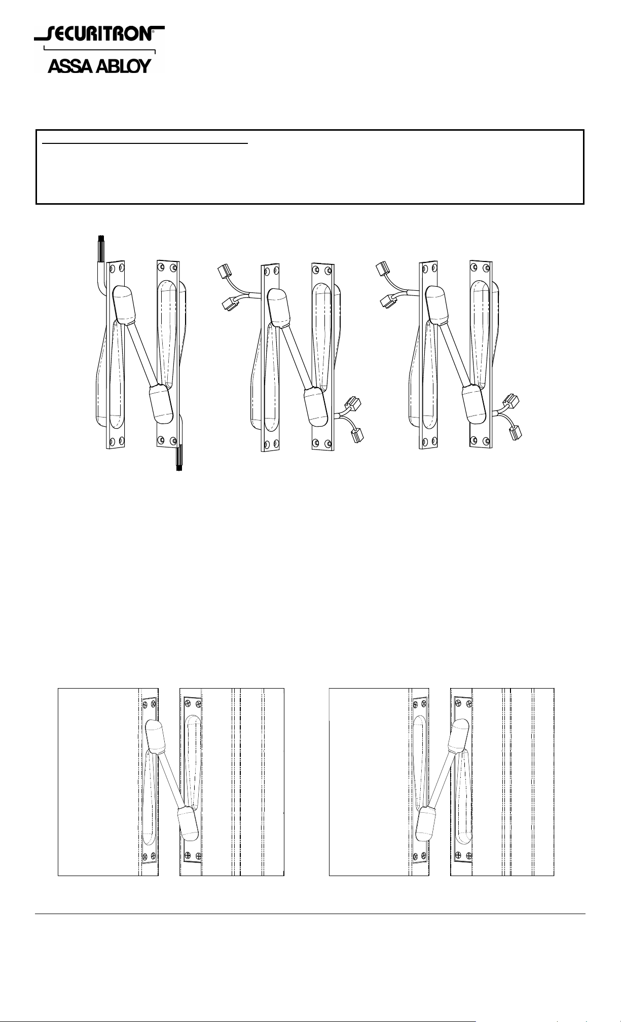
Available CEPT Models:
CEPT-10
Traditional Connect
10 Wire (2 + 8)
(2) Wire Nut
+ (8) Crimp
EL-CEPT
ElectroLynx®
(Assa Abloy)
12 Wire (8 + 4)
Connectors: 8 Pin + 4 Pin
(TIA/EIA-568-B Compatible)
Connectors: 6 Pin + 4 Pin
CEPT-C5E
CAT 5e
9 Wire (8 + 1)
DESCRIPTION
The Concealed Electrical Power Transfer CEPT unit is designed to provide a secu re multiple wire
power and/or data transfer between a door frame and door. The unit mounts directly between
the frame and door along the hinged edge and is available in three multi-wire configurations.
The CEPT is non-handed, allows mechanical (hinged) movement of the door and is totally
concealed when the door is fully closed. This manual provides the information required to
successfully install a CEPT to a standard hinged door opening.
© Copyright, 2011, all rights reserved PN# 500-22115
Page 1 Rev. C, 05/11
Page 2
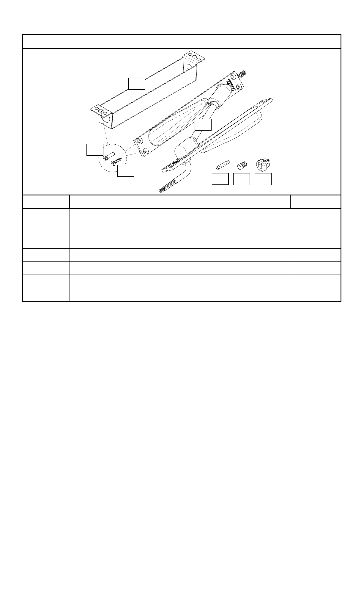
Components included with this Product:
B
A
C
D
G
F
E
Item Description Quantity
A CEPT Assembly 1
B Back Box 2
C Screws, 10-24 x 3/4” Phillips Flat Head Undercut (for metal) 13
D Screws, #10 x 3/4” Phillips Flat Head (for wood) 13
E Strain Relief Bushing 2
F Wire Nut (CEPT-10 Only) 4
G Dolphin™ Connector (CEPT-10 Only) 17
RECOMMENDED TOOLS
Basic for Factory Prepped Door Install: Additional for More Detailed Install:
Hammer
Flat Tip Screwdriver: 1/4”
Phillips Screwdriver: #2
Wire Strippers/Crimpers
Pliers
Center Punch
Drill Motor & Bits
Reciprocating Saw & Blades
Router & Bits
Chisel
Metal File
SPECIFICATIONS
Physical
For proper installation and operation of the CEPT, the thickness of the door should be 1-3/4”
minimum. The door opening limitations listed here apply to a (1-3/4”) door equip ped with the
following hinge sizes and configurations.
Door Hinge Configuration:
Door Opening Angle Range:
Up to 5” Butt Hinge 0-180°
5-1/2” Butt Hinge 0-130°
6” Butt Hinge 0-110°
PN# 500-22115
Page 2 Rev. C, 05/11
Page 3

Electrical
(
(
)
The following chart shows the electrical specifications for each CEPT model.
MODEL TYPE WIRE SIZE/QTY CURRENT LIMIT (Per Wire)
18 AWG/2 Max. 5A
CEPT-10 10 Wire (2+8)
22 AWG/8 Max. 1A
EL-CEPT ElectroLynx® (8+4) 22 AWG/12 Max. 1A
24 AWG/8 Max. 1A
CEPT-C5E CAT 5e (8+1)
22 AWG/1 Ground (Max. 1A)
INSTALLATION INSTRUCTIONS
NOTE: The CEPT should always be mounted above the second hinge from the floor.
The CEPT was designed primarily to be installed into a factory prepped door and frame.
However, the unit can be installed into an un-prepped door and frame by following the specific
instructions provided on the product installation diagram. The following exploded illustration
shows the included hardware required to properly install a CEPT to a factory prepped door
opening (CEPT-10 shown).
Prepped) Door
Back Box(es
Prepped) Frame
CEPT
To install the CEPT to a factory prepped door and frame:
Route/pull utility wires/cable through the prepped holes in door and frame.
Pop out the desired knock-out hole in the back box.
Notes:
1. Back boxes are normally required to meet fire code requirements.
2. The 7/8” diameter knock-out holes in the back boxes are provided for EMT type
electrical conduit fittings.
3. The 5/8” diameter knock-out holes are for use of the provided strain relief bushings.
To install the strain relief bushing, lay the utility cable (not included) into the slotted
opening in the bushing allowing a sufficient wire length (loop) for making connections.
Fold the hinged retainer over the cable, squeeze together using pliers and then insert
through the 5/8” [15.9mm] knock-out in the back box.
PN# 500-22115
Page 3 Rev. C, 05/11
Page 4

When required, install the appropriate connectors for ElectroLynx® or CAT 5e (not
included) to the end of your utility cable.
Using a #2 Phillips screwdriver, attach each back box to the door and/or frame using the
10-24 x 3/4” long screws (for metal) or the #10 x 3/4” long screw s (for wood). These
screws are to be placed through the center hole in each flange of the back box.
Metal Door Prep. Wood Door Prep.
Back Box
10-24 X 3/4”
CEPT
Back Box
#10 X 3/4”
CEPT
Make connections to the CEPT by:
o Using the connectors (EL-CEPT or CEPT-C5E models).
o Using the provided wire nuts for connection of the two (2) 18 AWG wire s - and by
using the Dolphin™ (crimp type) connectors to make the appropriate connections to
the remaining 22 AWG wires (CEPT-10 model).
Using a #2 Phillips screwdriver, assemble each side of the CEPT to the door and frame
using the 10-24 x 3/4” long screws (for metal) or the #10 x 3/4” lon g screws (for wood).
These screws are to be placed through the four corner holes in the face flange of each of
the CEPT housings and also through the outer (clearance) holes in the back box.
MAGNACARE
For warranty information visit www.securitron.com/en/site/securitron/About/MagnaCare-Warranty/
LIFETIME REPLACEMENT WARRANTY
PN# 500-22115
Page 4 Rev. C, 05/11
 Loading...