

Securitron EL-DSB-CL, EL-DSB-BK, DSB-BK, DSB-BKI, DSB-CL User Manual
...
ASSA ABLOY, the global leader in
door opening solutions
SERIES DSB DUAL SENSE BAR
INSTALLATION and OPERATION
INSTRUCTIONS
Securitron Magnalock Corp. www.securitron.com
Tel 800.624.5625 techsupport@securitron.com
© Copyright, 2011, all rights reserved PN# 500-22700
Rev. F, 03/11
Securitron Magnalock Corp. www.securitron.com ASSA ABLOY, the global leader
1X 4X
Tel 800.624.5625 techsupport@securitron.com
in door opening solutions
SECURITRON SERIES DSB DUAL SENSE BAR
INSTALLATION AND OPERATION INSTRUCTIONS
1. INTRODUCTION
The Securitron Dual Sense Bar (Model DSB) is an exit device intended for use on magnetically
locked, non-fire rated doors only. The bar will operate via mechanical movement (push) to
provide a primary egress function that does not require human touch in addition to function by
touch sense. The mechanical function has been included to simplify use and ease exit for
personnel with prosthetics or those who may otherwise have their hands occupied (e.g. carrying
boxes, manipulating carts, maneuvering wheelchairs, etc.). The assembly consists of an
aluminum bar available in lengths to fit standard U.S. door openings: (36", 42", and 48"). The
end mounts provide the mounting platform for the bar and house the electronic PC boards and
mechanical switching mechanisms within the bar.
2. SPECIFICATIONS
MECHANICAL ELECTRICAL
Physical Size:
Height: 3” [76mm]
Depth: 3” [76mm] (from mounting surface)
Overall Length:
36” Door = 34-3/16” [868mm]
42” Door = 40-3/16” [1021mm]
48” Door = 46-3/16” [1173mm]
Operating Force (Maximum): 15 Lbs. [66.7N]
Environmental (Recommended):
Temperature Range: 32ºF [0ºC] to
120ºF [49ºC]
Humidity: 10% to 90% RH
3. PRODUCT OVERVIEW
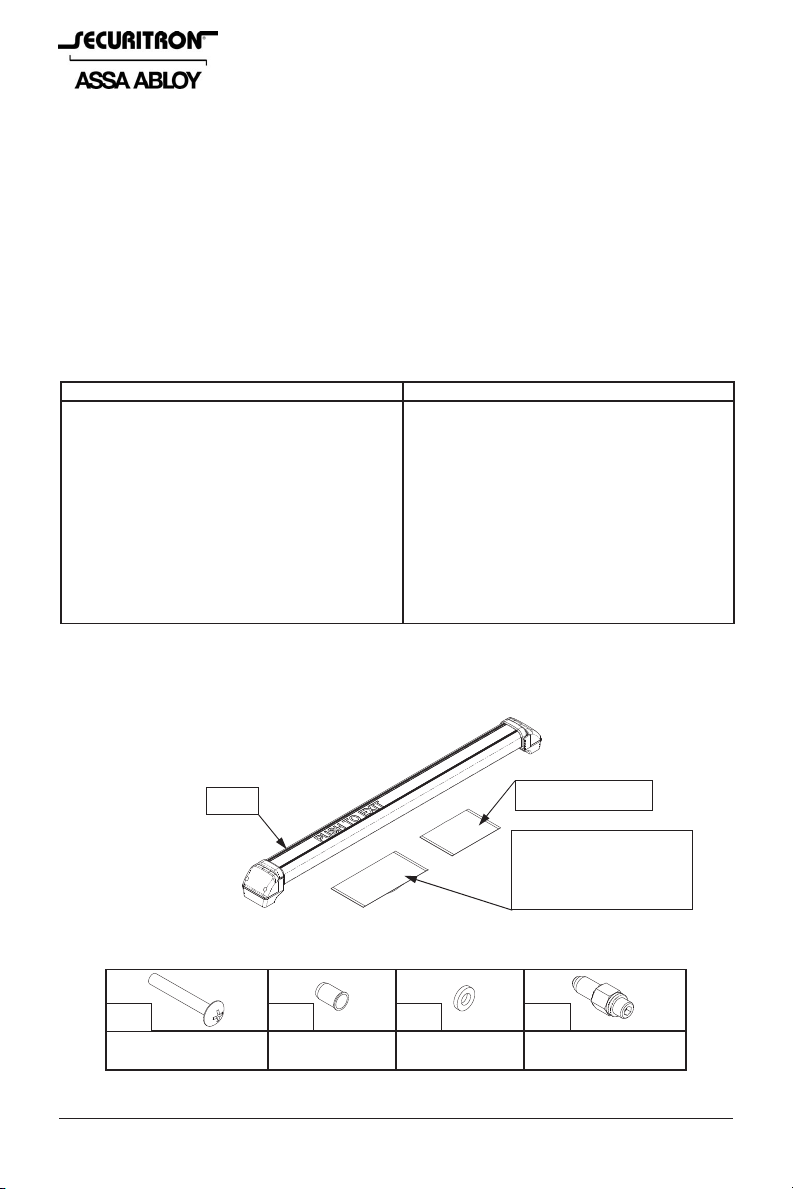
Upon unpacking this product, an inventory should be made to ensure that all the required
components and hardware have been included. Along with these instructions, the DSB product
should include the following items:
Voltage Input: 12 or 24 Volts DC
Current Draw (Base - At Rest): 24mA
(DPST) Contact Rating: 1 Amp @ both 12
and 24VDC
Illuminated Sign (Option): 20mA Maximum
(additional)
DSB Connection: 16-Foot [4.88 Meter] Wire
Cable with Traditional Connector
ELDSB Connection: Wiring Harness with
ElectroLynx Connector
DSB
Hardware Pack
Traditional Power
Cable (w/ TSB-C)
OR
ElectroLynx Harness
Figure 1
4. HARDWARE (U.S. STANDARD)
4X
Phillips Truss Head
Screw, 1-3/4” Long
4X
Blind Nut
Plastic Flat
Washer
Blind Nut Collapsing
Tool
© Copyright, 2011, all rights reserved PN# 500-22700
Page 1 Rev. F, 03/11
Fasteners for metal doors (aluminum frame and hollow steel) are included. For through door
mounting please call Securitron for a no-charge DSB-TDM kit. Note that US standard or metric
fasteners are supplied depending on the version of the bar which was ordered. (The metric
version part number for a DSB series bar will include the suffix “M”).
5. RECOMMENDED TOOLS
Bubble Level Power Drill
Hammer Pliers, Vise-grip
Center Punch
Wrenches:
1/2” Box-end (or Adjustable Wrench)
Drill Bits:
3/8” [9.5mm], 11/16” [17.5mm]
Screwdrivers:
#1 and #2 Phillips, 1/8” [3mm] Flat
Standard DSB Hex Wrench: 3/16”
Metric DSB Hex Wrench: 5mm
6. INSTALLATION INSTRUCTIONS
AS THE DSB IS NORMALLY USED TO ALLOW EGRESS ON AN ELECTRICALLY SECURED
DOOR, ENSURE THAT ALL APPLICABLE BUILDING AND FIRE CODES ARE BEING
FOLLOWED. VERIFY INSTALLATION WITH LOCAL BUILDING AND/OR FIRE
PREVENTION CODES AND REGULATIONS.
THE DUAL SENSE BAR MAY NOT BE USED ON A FIRE RATED DOOR THAT REQUIRES A
FIRE RATED LATCH! THE DSB HAS NO LATCH. IN SOME INSTANCES HOWEVER, FIRE
DOORS ARE ALLOWED ON OPENINGS WHERE A FIRE RATED BARRIER IS NOT
REQUIRED. USE OF THE DSB SHOULD ALWAYS BE VERIFIED AND APPROVED
THROUGH LOCAL BUILDING CODE AND/OR FIRE PREVENTION DEPARTMENTS.
6.1. BAR POSITIONING AND MOUNTING HOLE MARKING
Using a #1 Phillips screwdriver, remove the screws and the end caps from both ends of the bar.
Verify that the bar is the correct length for the door. If it appears that the bar is longer than it
should be for the door, see Section 6.6 for cutting instructions. Take note of which end has the
main (touch sense) PC board in it, this end has a ring terminal connecting the PCB to the bar
profile. This is the end that should be mounted on the hinge side for the most convenient wire
exit from the door.
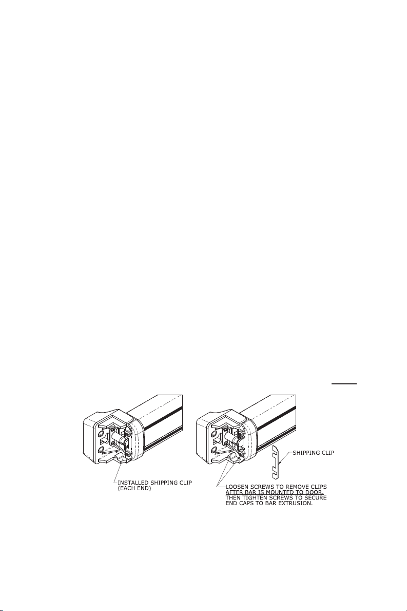
The DSB, as shipped from the factory, is assembled with shipping clips at each end that
temporarily hold the bar together while positioning and mounting the bar to the door (see
Figure 2).
FOR EASE OF INSTALLATION, DO NOT REMOVE THE SHIPPING CLIPS UNTIL AFTER
THE
BAR HAS BEEN MOUNTED.
Figure 2
For best results, the assembled DSB itself may be used as a template to locate and mark the
mounting holes. When positioning the bar for marking the holes, ensure the following:
The bar is positioned at the correct height from the floor (see Figure 3).
Generally, US Building Codes require that the bar be located between 30 inches [762mm] and
44 inches [1118mm] from the bottom of the door.
PN# 500-22700
Page 2 Rev. F, 03/11
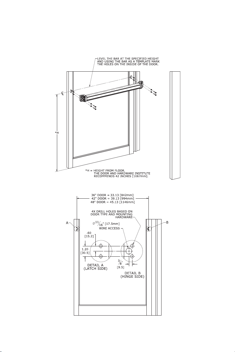
The bar is level.
The bar is centered on the door (left to right) between the door frame stops.
By using the assembled bar as a template, the correct separation between the mounting holes
will automatically be maintained. After marking the hole locations, verify that the centers of the
holes are at the required distance as shown in Figure 4.
Figure 3
Figure 4
PN# 500-22700
Page 3 Rev. F, 03/11
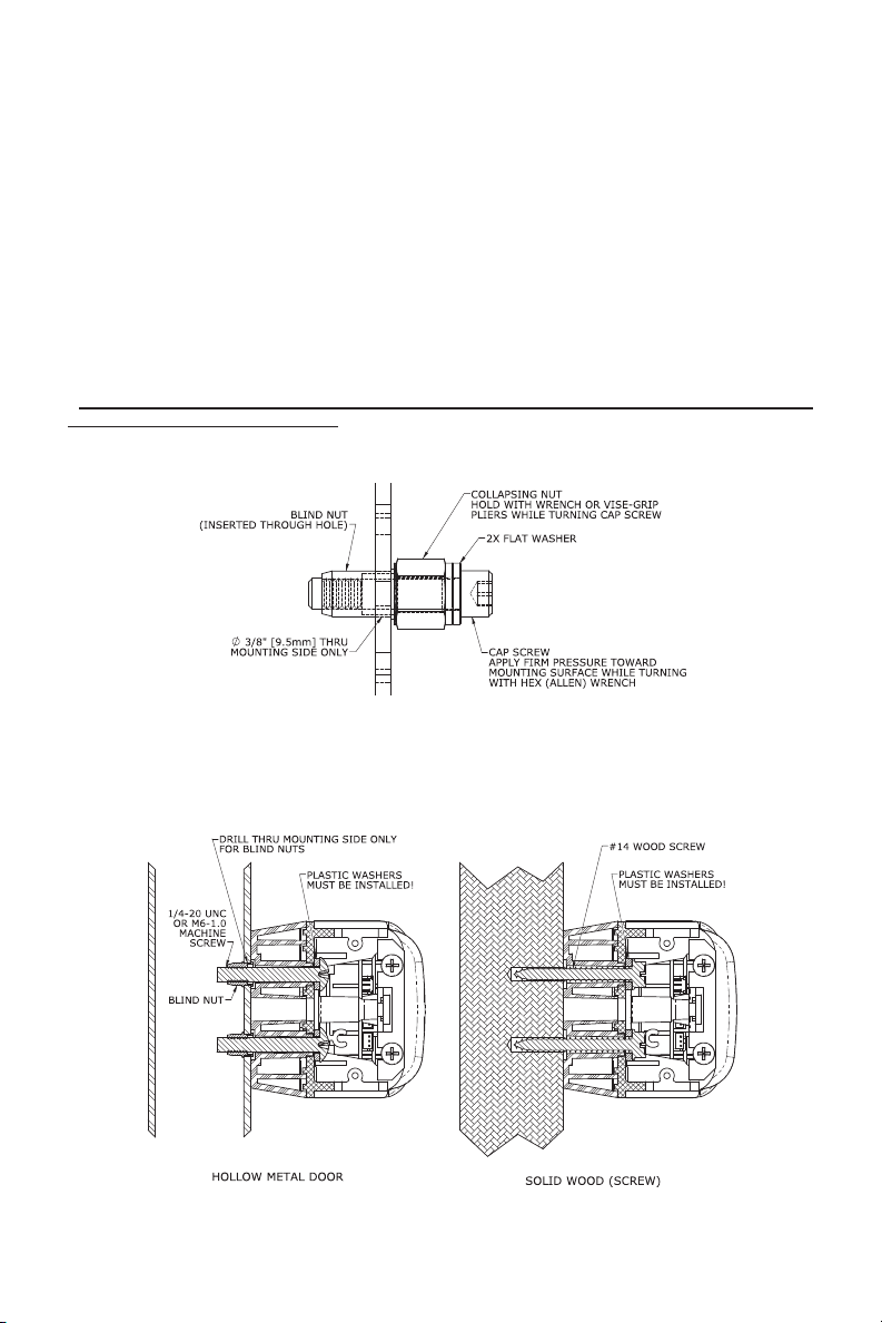
6.2. HOLLOW METAL DOOR PREPARATION
The bar should be mounted to the door using the blind nuts and screws provided as shown in
Figure 6. Use the following step-by-step instructions and Figure 5 for the installation of the
blind nuts:
a. Drill the four (4) 3/8” [9.5mm] diameter holes through the interior (mounting) surface of the
door at the previously marked hole locations. DO NOT drill completely through the door.
b. Insert one blind nut assembled to the installation tool into a mounting hole.
c. While holding the collapsing nut of the tool with a 1/2” box-end wrench, turn the socket head
cap screw using a 3/16” (or 5mm) hex wrench. Note: Maintain firm pressure toward the
mounting surface while collapsing the nut.
d. Once the blind nut is adequately collapsed, remove the tool from the installed nut by backing
the cap screw out of the blind nut.
e. Install all blind nuts by using the collapsing tool and repeating the previous steps.
f. After all blind nuts are installed, hold the bar in place over the blind nuts and secure into
place with the *plastic washers and mounting screws provided.
*THE PLASTIC WASHERS MUST BE INSTALLED UNDER THE SCREW HEADS FOR THE
DSB TO FUNCTION PROPERLY. ALSO ENSURE THAT THERE IS 1/32” CLEARANCE
BETWEEN EACH BAR END CAP AND THE INNER FLANGE OF THE BASE MOUNT BEFORE
FINAL TIGHTENING OF THE MOUNTING SCREWS.
Figure 5
6.3. SOLID WOOD DOOR PREPARATION:
The bar may be mounted using wood screws (not furnished). Four (4) #14 wood (or SMS)
screws with a hex head are recommended (see Figure 6).
Figure 6
PN# 500-22700
Page 4 Rev. F, 03/11
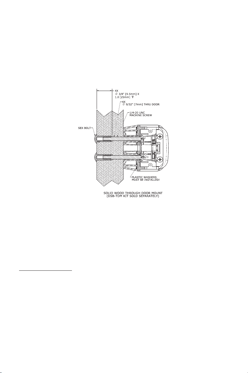
6.4. BOLT THROUGH DOOR PREPARATION:
For through-bolt mounting on various door types a DSB-TDM kit will be required (see Figure 7).
This product accessory is furnished separately and can be ordered from the factory at no charge.
This configuration may be used on solid wood doors, hollow or solid metal doors, or chalk filled
*fire doors. Please follow instructions included with the DSB-TDM kit for proper installation.
*THE DUAL SENSE BAR MAY NOT BE USED ON A FIRE RATED DOOR THAT REQUIRES A
FIRE RATED LATCH! THE DSB HAS NO LATCH. IN SOME INSTANCES HOWEVER, FIRE
DOORS ARE ALLOWED ON OPENINGS WHERE A FIRE RATED BARRIER IS NOT
REQUIRED. USE OF THE DSB SHOULD ALWAYS BE VERIFIED AND APPROVED
THROUGH LOCAL BUILDING CODE AND/OR FIRE PREVENTION DEPARTMENTS.
Figure 7
6.5. WIRE ACCESS HOLES
The DSB connects to a power source and access control systems via either a 16-foot 6conductor traditional wiring cable assembly (included with the standard DSB series), or an 8conductor ElectroLynx connector “pigtail” harness (included with the ELDSB series).
All DSB/ELDSB installations require that an 11/16” [17.5mm] diameter wire way hole be located
in the hinge side of the door at the position shown (see Figure 4). This hole allows either the
traditional cable with connector or the ElectroLynx wiring harness connectors to be pulled into
the door.
DSB – Traditional Wiring
:
Wire routing from a hollow door implementing the traditional wiring method may be achieved
using a door cord. The TSB-C (included with the standard DSB) may be mounted toward the top
of the door between the door and frame, or mounted directly between the bar end mount and
frame (see Appendix B). Other commercially available electrical transfer hinges or pivots (such
as Securitron’s EPT or EPTL Electric Power Transfer) may also be used to route the wiring from
the door to the frame in a concealed manner. The following step-by-step instructions may be
used for the installation of the armored door cord between the door and frame:
a. Drill a 3/8” [9.5mm] diameter hole in the door and frame (hinge side) as shown in Figure 8.
b. Insert one (1) door cord insert into each end of the flexible cord conduit.
c. Run electrical wiring as required through the flexible cord conduit (with inserts) and the holes
in the door and frame.
d. Position the door cord caps to completely cover each 3/8” [9.5mm] diameter hole and use
the cap mounting holes as a template to mark and then drill two (2) 1/8” [3.2mm] pilot holes
for mounting.
PN# 500-22700
Page 5 Rev. F, 03/11
 Loading...