

seca 515/514
Administrator Manual
Software version 1.1 from
Build 550

English
CONTENTS
1. Device description . . . . . . . . . . . . . . . . . . . . . . . . . . . . 3
1.1 Intended use . . . . . . . . . . . . . . . . . . . . . . . . . . . . . 3
1.2 Description of function. . . . . . . . . . . . . . . . . . . . . . 3
Calculating weight and height . . . . . . . . . . . . . . 3
Bioimpedance measurement. . . . . . . . . . . . . . . 3
Administering patient data. . . . . . . . . . . . . . . . . 3
Evaluation . . . . . . . . . . . . . . . . . . . . . . . . . . . . . 3
Administration of user data . . . . . . . . . . . . . . . . 4
Data transmission and network functions . . . . . 4
Compatibility . . . . . . . . . . . . . . . . . . . . . . . . . . . 4
1.3 User qualification . . . . . . . . . . . . . . . . . . . . . . . . . . 4
Administration/network connection . . . . . . . . . . 4
Measuring mode . . . . . . . . . . . . . . . . . . . . . . . . 4
1.4 Contraindications. . . . . . . . . . . . . . . . . . . . . . . . . . 5
2. Safety information . . . . . . . . . . . . . . . . . . . . . . . . . . . . 6
2.1 Safety instructions in these instructions for use . . . 6
2.2 Basic safety instructions . . . . . . . . . . . . . . . . . . . . 6
Handling the device. . . . . . . . . . . . . . . . . . . . . . 6
Preventing electric shock. . . . . . . . . . . . . . . . . . 7
Preventing injuries and infections. . . . . . . . . . . . 7
Preventing device damage . . . . . . . . . . . . . . . . 8
Dealing with measuring results . . . . . . . . . . . . . 8
Dealing with packaging . . . . . . . . . . . . . . . . . . . 9
3. Device overview . . . . . . . . . . . . . . . . . . . . . . . . . . . . . 10
3.1 Controls . . . . . . . . . . . . . . . . . . . . . . . . . . . . . . . 10
3.2 Symbols in the start display . . . . . . . . . . . . . . . . . 12
3.3 Color symbols and other controls . . . . . . . . . . . . 14
3.4 Menu structure . . . . . . . . . . . . . . . . . . . . . . . . . . 16
3.5 Identification on the device and the type plate . . . 17
3.6 Identification on the packaging . . . . . . . . . . . . . . 18
4. Making the device operational . . . . . . . . . . . . . . . . . 19
4.1 Scope of delivery. . . . . . . . . . . . . . . . . . . . . . . . . 19
4.2 Establishing power supply . . . . . . . . . . . . . . . . . . 20
4.3 Setting up the device. . . . . . . . . . . . . . . . . . . . . . 20
4.4 Operating the device in a PC network . . . . . . . . . 21
Connecting the network via Ethernet or
seca 360° wireless network . . . . . . . . . . . . . . . 21
Print . . . . . . . . . . . . . . . . . . . . . . . . . . . . . . . . 22
Indirect connection via USB memory stick. . . . 22
4.5 Operation using a seca 360° stadiometer . . . . . . 23
5. Operating concept . . . . . . . . . . . . . . . . . . . . . . . . . . . 24
5.1 Swiveling the touchscreen display . . . . . . . . . . . . 24
5.2 Switch on device . . . . . . . . . . . . . . . . . . . . . . . . . 24
5.3 Selecting functions . . . . . . . . . . . . . . . . . . . . . . . 24
5.4 Selecting extended functions. . . . . . . . . . . . . . . . 25
5.5 Entering text . . . . . . . . . . . . . . . . . . . . . . . . . . . . 25
5.6 Entering numbers . . . . . . . . . . . . . . . . . . . . . . . . 26
5.7 Measuring procedure . . . . . . . . . . . . . . . . . . . . . 26
5.8 Automatic standby . . . . . . . . . . . . . . . . . . . . . . . 27
5.9 Switching off the device. . . . . . . . . . . . . . . . . . . . 27
6. Configuring the device. . . . . . . . . . . . . . . . . . . . . . . . 28
6.1 Adapting the default module selection for
bioimpedance analysis . . . . . . . . . . . . . . . . . . . . 28
Showing/hiding default module selection. . . . . 28
Creating default module selection . . . . . . . . . . 29
6.2 Administering user accounts and access rights . . 30
6.3 Calling up the Administrator menu. . . . . . . . . . . . 30
6.4 Making default settings . . . . . . . . . . . . . . . . . . . . 32
Setting units of measurement . . . . . . . . . . . . . 32
Making regional settings . . . . . . . . . . . . . . . . . 32
Setting the date and time . . . . . . . . . . . . . . . . 35
Setting display brightness and volume. . . . . . . 36
6.5 Setting up the network . . . . . . . . . . . . . . . . . . . . 36
Requirements . . . . . . . . . . . . . . . . . . . . . . . . . 36
Network services. . . . . . . . . . . . . . . . . . . . . . . 36
Network-dependent functions . . . . . . . . . . . . . 37
Integrate device in an Ethernet network. . . . . . 37
Setting up seca CLS network
(via Ethernet only). . . . . . . . . . . . . . . . . . . . . . . 38
Setting up the seca 360° wireless network . . . 40
Viewing wireless devices . . . . . . . . . . . . . . . . . 42
6.6 System data . . . . . . . . . . . . . . . . . . . . . . . . . . . . 43
Viewing versions . . . . . . . . . . . . . . . . . . . . . . . 43
Making system settings. . . . . . . . . . . . . . . . . . 43
Using service functions . . . . . . . . . . . . . . . . . . 48
6.7 Saving settings . . . . . . . . . . . . . . . . . . . . . . . . . . 50
Applying settings. . . . . . . . . . . . . . . . . . . . . . . 50
Exiting the administrator menu . . . . . . . . . . . . 50
7. Troubleshooting . . . . . . . . . . . . . . . . . . . . . . . . . . . . . 51
7.1 Power supply and display . . . . . . . . . . . . . . . . . . 51
7.2 Height and weight . . . . . . . . . . . . . . . . . . . . . . . . 51
7.3 Bioimpedance analysis . . . . . . . . . . . . . . . . . . . . 52
7.4 Data transmission . . . . . . . . . . . . . . . . . . . . . . . . 53
7.5 Print . . . . . . . . . . . . . . . . . . . . . . . . . . . . . . . . . . 55
8. Optional accessories . . . . . . . . . . . . . . . . . . . . . . . . . 55
9. Spare parts . . . . . . . . . . . . . . . . . . . . . . . . . . . . . . . . . 56
10. Technical information . . . . . . . . . . . . . . . . . . . . . . . 56
10.1 The seca 360° wireless network . . . . . . . . . . . . 56
10.2 Technical modifications . . . . . . . . . . . . . . . . . . . 56
10.3 Additional technical information . . . . . . . . . . . . . 57
11. Disposal. . . . . . . . . . . . . . . . . . . . . . . . . . . . . . . . . . . 57
12. Warranty . . . . . . . . . . . . . . . . . . . . . . . . . . . . . . . . . . 57
13. Declaration of conformity . . . . . . . . . . . . . . . . . . . . 57
2 •

English
1. DEVICE DESCRIPTION
1.1 Intended use
1.2 Description of function
The medical Body Composition Analyzer seca 515/514 is mainly used in
hospitals, medical practices and inpatient care facilities in accordance with
national regulations. The
electric impedance measurements and parameters, e.g. fat-free mass (FFM),
which can be derived from them for automatic calculation. The results are displayed graphically and assist the attending physician with the following medical issues:
• determining energy expenditure and energy reserves as a basis for
nutritional advice
• assessing metabolic activity and the success of a training program, e.g.
within the framework of rehabilitation or physiotherapy
• determining a patient's fluids status
• determining general state of health or, in the case of a previously-known
disease, assessing its severity
seca 515/514 is not a diagnostic device. To make an accurate diagnosis,
The
the physician needs to commission thorough examinations and take their
results into account in addition to the results of the
seca 515/514 device records weight, height and bio-
seca 515/514.
Calculating weight and height The device uses an electronic scale. Weight is recorded across 4 load cells.
Height is recorded via manual entry or via wireless transmission from a
seca 360° stadiometer.
Bioimpedance measurement Bioimpedance is measured according to the 8-point method. The flow of the
low alternating current and the measurement of impedance are performed for
each side of the body using a pair of foot electrodes and 3 pairs of hand electrodes. The hand electrodes are attached at different heights so that persons
with a height of between 1.60 m and 2.0 m can adopt the ideal position on
the device for a bioimpedance measurement.
Administering patient data seca patient files can be created directly on the device for administering mea-
sured results. The seca patient files are stored in the patient database of the
seca analytics 115 PC software supplied. Alternatively, seca patient files can
be saved on the USB memory stick supplied. The USB memory stick likewise
contains a seca patient database.
seca patient files and seca patient databases contain exclusively data necessary for working with seca products or determined using seca products. seca
patient files can be administered and edited only using the
software. The export and import functions of the
be used for exchanging data with surgery and hospital information systems.
seca 115 PC software can
seca 115 PC
Evaluation Bioimpedance measurements are evaluated in graphical form based on sci-
entifically-established formulas. An in-house study by seca established formulas for determining the parameters of total body water (TBW), extracellular
water (ECW), fat-free mass (FFM) and skeletal muscle mass (SMM) for arms,
legs, torso and the whole body. In the same studies, in-house reference values were determined for the following parameters, in order to allow normal
ranges to be shown: bioelectric impedance vector analysis (BIVA), mass indices (FMI, FFMI), phase angle (φ). You can find further information in the
Instructions for Use for Physicians and Assistants.
Device description • 3

Administration of user data Access data for users of the device is administered in the seca 115 PC
software supplied. A user PIN for the seca 515/514 is generated automatically
when user accounts for the seca 115 are created. The administrator also has
the option of specifying a user PIN him or herself.
The device can only be configured with administrator rights. An initial administrator PIN for the device is provided. It can only be changed on the device.
The creation and administration of user data is only necessary if the seca
patient database of the
device.
seca 115 PC software is to be accessed from the
Data transmission and network
functions
Compatibility This device (software version 1.1 from Build 550) is compatible only with ver-
The device is networkable. The network connection allows the device to use
both the seca patient database and the special print function of the seca 115
PC software.
The special print function of the
start printing out a detailed results report directly on the medical Body
Composition Analyzer
Alternatively to the Ethernet link, seca mBCAs and the
can communicate wirelessly via seca 360° technology. For this purpose, the
seca 360° wireless USB adapter 456 (included in the scope of delivery) must
be connected to a PC on which at least the application software of the
seca 115 is installed.
seca 360° stadiometers can wirelessly transmit measured results to the
device.
The device has the following interfaces:
• on the weighing platform
– network connection (Ethernet)
• on the touchscreen display
– internal seca wireless module
– USB interface for connecting a USB memory stick (included in the
scope of delivery)
sion 1.4 from Build 560 of the
compatibility with older versions of the seca 115. For a summary of technical
modifications, see the section entitled “Technical modifications” on page 56.
seca mBCAs with older device software can be updated. Go to
www.seca.com and contact your local seca service partner.
seca 515/514.
seca 115 PC software makes it possible to
seca 115 PC software
seca 115 PC software. There is no downward
1.3 User qualification
Administration/network connection The device may only be set up and incorporated in a network by experienced
administrators or hospital technicians.
Measuring mode The device and the seca 115 PC software may only be operated by persons
with sufficient specialist expertise.
4 •

English
1.4 Contraindications
Bioimpedance measurements may not be performed on patients exhibiting
the following characteristics:
• electronic implants, e.g. cardiac pacemakers
• active prostheses
Bioimpedance measurements may
connected to one of the following devices:
• electronic life-support systems, e.g. artificial heart, artificial lung
• portable electronic medical devices, e.g. ECG devices or infusion pumps
Impedance measurements may only be performed on persons exhibiting the
following characteristics after discussion with the attending physician:
• cardiac arrhythmias
• pregnancy
not be performed on persons who are
Device description • 5

2. SAFETY INFORMATION
2.1 Safety instructions in these instructions for use
DANGER!
Identifies an exceptionally hazardous situation. If you fail to take note
of this information, serious irreversible or fatal injury will result.
WARNING!
Identifies an exceptionally hazardous situation. If you fail to take note
of this information, serious irreversible or fatal injury may result.
CAUTION!
Identifies a hazardous situation. If you fail to take note of this
information, minor to moderate injury may result.
ATTENTION!
Indicates that the product may have been operated incorrectly. If you
fail to take note of this information, the device may be damaged or the
measured results may be incorrect.
NOTE:
Contains additional information on how to use this device.
2.2 Basic safety instructions
Handling the device ► Please take note of the instructions in these instructions for use.
► Keep the instructions for use in a safe place. The instructions for use are a
component of the device and must be available at all times.
DANGER!
Risk of explosion
Do not use the device in an environment in which one of the following
gases has accumulated:
► oxygen
► flammable anesthetics
► other flammable substances/gas mixtures
CAUTION!
Hazard to patient, damage to device
Additional devices connected to medical electrical devices must
►
provide evidence of compliance with the relevant IEC or ISO standards (e.g. IEC 60950 for data-processing devices). Furthermore, all
configurations must comply with the requirements of standards for
medical systems (see IEC 60601-1-1 or Section 16 of the 3rd edition of IEC 60601-1 respectively). Anyone connecting additional devices to medical electrical devices is considered a system configurer
and is therefore responsible for ensuring that the system complies
with the requirements of standards for systems. Your attention is
drawn to the fact that local laws take precedence over the abovementioned requirements of standards. In the event of any queries,
please contact your local specialist dealer or Technical Service.
► Please have maintenance, subsequent verification (seca 515 only)
and BIA measuring technology checks performed every two years.
► Technical modifications may not be made to the device. The device
does not contain any parts for servicing by the user. Please only
have maintenance, technical checks and repairs performed by an
authorized service partner. You can find a service partner in your
area at www.seca.com or by sending an e-mail to
service@seca.com.
► Use only original accessories and seca spare parts, otherwise seca
will not grant any warranty.
6 •

English
CAUTION!
Hazard to patient, malfunction
Keep other medical devices, e.g. high-frequency surgical devices,
►
at a minimum distance of approx. 1 meter to prevent incorrect
measurement or wireless transmission interference.
► Keep high-frequency devices such as cellphones at a minimum
distance of approx. 1 meter to prevent incorrect measurement or
wireless transmission interference.
► The actual transmission output of high-frequency equipment may
require minimum distances of more than 1 meter. For details, go to
www.seca.com.
Preventing electric shock WARNING!
Electric shock
Set up devices which can be operated with a power pack so that
►
the power supply socket is within easy reach and the power supply
can be quickly disconnected.
► Ensure that your local power supply matches the details on the
power pack.
► Never touch the power pack with wet hands.
► Do not use an extension cable and multiple outlets. This also applies
to the USB connection on the touchscreen display.
► Make sure that the power cable is not crushed and cannot be
damaged by sharp edges.
► Do not operate the device above an altitude of 3000 m.
Preventing injuries and infections WARNING!
Hazard to patient
Subject the device to a hygiene treatment after each measurement
►
(see “Troubleshooting” on page 51).
► Ensure that the patient does not have any contagious diseases.
► Ensure that the patient does not have any open wounds on the
palms of their hands or the soles of their feet.
► Ensure that the device is steady and level.
► The device is not designed as a standing aid. Assist people with
limited mobility, e.g. when they are getting up from a wheelchair.
► Ensure that the weighing platform is dry before the patient steps
onto it.
► Ensure that the patient has dry feet before stepping onto the
weighing platform.
► Ensure that the patient does not step directly onto the edges of the
weighing platform.
► Ensure that the patient steps onto the weighing platform slowly and
safely.
► Route the network and power cables such that no one can trip over
them.
WARNING!
Risk of infection
Before and after every measurement, wash your hands to reduce
►
the risk of cross-contamination and nosocomial infections.
► Hygienically reprocess the scale regularly as described in the re-
spective section in this document.
► Make sure that the patient has no infectious diseases.
► Make sure that the patient has no open wounds or infectious skin
alterations, which may come into contact with the device.
Safety information • 7

Preventing device damage ATTENTION!
Damage to device
Make sure that fluids never get inside the device. These can destroy
►
the electronics.
► Switch off the device before you disconnect the power pack from
the power supply.
► If the device is not be used for an extended period, disconnect the
power pack from the power supply. Only then is the device deenergized.
► Do not drop the device.
► Do not subject the device to shocks or vibrations.
► Do not place the device in direct sunlight and make sure that it is not
placed in the direct proximity of a heat source. The excessive temperatures could damage the electronics.
► Perform a function check at regular intervals as described in the cor-
responding section in the “Instructions for Use for Physicians and
Assistants”. Do not operate the device if it is not working properly or
is damaged.
► Avoid rapid temperature changes. If the device is transported so
that a temperature difference of over 20 °C occurs, the device must
be left to stand for at least 2 hours before it is switched on, otherwise condensation may form; this can damage the electronics.
► Use only disinfectants free of chlorine and alcohol and which are ex-
plicitly suitable for acrylic sheet and other sensitive surfaces (active
ingredient: quaternary ammonium compounds, for example).
► Do not use aggressive or abrasive cleaning agents.
► Do not use organic solvents (e.g. white spirit or petroleum spirit).
Dealing with measuring results WARNING!
Hazard to patient
The seca 515/514 is not a diagnostic device. The device assists the
attending physician in reaching a diagnosis.
► To reach a precise diagnosis and to initiate therapies, the attending
physician must have thorough examinations conducted and take
the results of these into consideration, as well as using the seca 515/
514
.
► The responsibility for diagnoses and the therapies derived from
them lies with the attending physician.
CAUTION!
Hazard to patient
To prevent misinterpretations, measured results for medical purposes
may only be displayed and used in SI units (weight: kilograms, height:
meters). Some devices have the option of displaying measured results
in different units. This is purely an additional function.
► Only use measurements in SI units.
► The user takes sole responsibility for the use of measured results in
non-SI units.
ATTENTION!
Loss of data
Before you save and re-use values measured with the seca 515/514
►
(e.g. in the seca PC software or in a hospital information system),
ensure that the measured values are plausible.
► If measured values have been transmitted from the seca 515/514
device to seca PC software or to a hospital information system, ensure before re-using them that the measured values are plausible
and assigned to the correct patient.
8 •

English
ATTENTION!
Measurements from third-party devices not compatible
Bioimpedance measurements performed by devices from different
manufacturers are not compatible. Follow-up measurements performed on a device other than a seca medical Body Composition
Analyzer may lead to inconsistent data and misinterpreted measured
results.
► Ensure that follow-up measurements are also performed on a seca
medical Body Composition Analyzer.
Dealing with packaging WARNING!
Danger of suffocation
Packaging made of plastic film (bags) presents a danger of
suffocation.
► Store packaging out of the reach of children.
► If the original packaging is no longer available, only use plastic bags
with safety holes to reduce the risk of suffocation.
NOTE:
Store the original packaging for future use (e.g. returning for
maintenance).
Safety information • 9
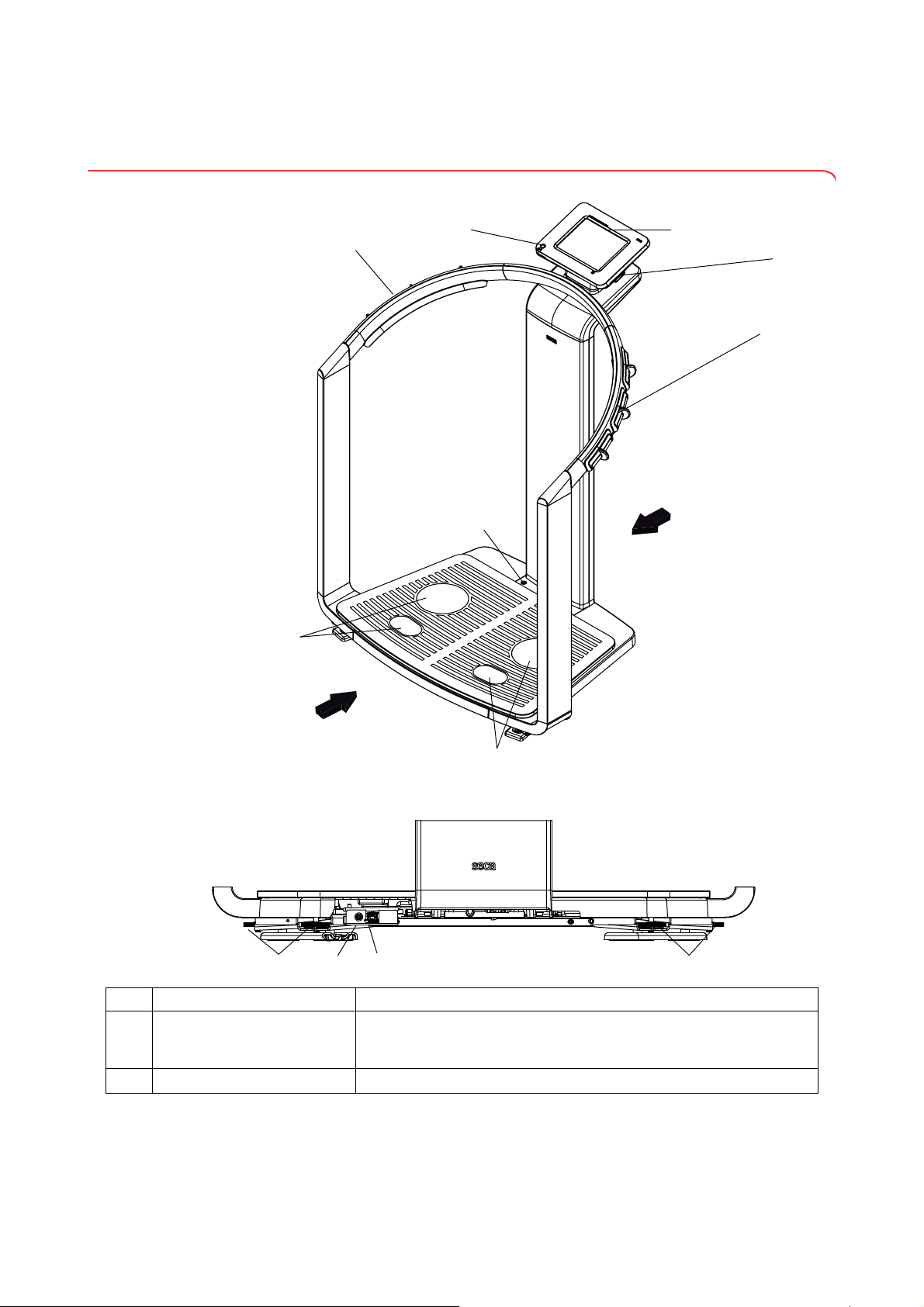
3. DEVICE OVERVIEW
2
3
6
4
7
5
1
8
91110 12
Front
Rear
Rear of weighing platform
3.1 Controls
No. Control Function
Switches device on: press button briefly
1
2
ON/OFF button with LED
Touchscreen display Central control and display element, can be swiveled 180° to left and right
Switches device to standby: press button briefly
Switches device off: press button and hold
10 •

English
No. Control Function
For connecting a USB memory stick (contained in the scope of delivery)
for administering the following data:
• creating seca patient files on the device
USB interface
3
Pair of hand electrodes, right
4
Spirit level Shows whether the device is horizontal
5
Pair of foot electrodes, right For heels and balls of feet, for bioimpedance measurement
6
Pair of foot electrodes, left For heels and balls of feet, for bioimpedance measurement
7
Pair of hand electrodes, left
8
Foot screws, right 2 pcs, for precise alignment of the device
9
Power pack connection For connecting the power pack
10
Ethernet interface For integrating the device in a PC network
11
Foot screws, left 2 pcs, for precise alignment of the device
12
• loading seca patient files from the seca 115 PC software supplied onto
the USB memory stick; calling up data on the device
• saving measured results to the USB memory stick
• reading out log files from the device (administrator function)
3 pcs. with finger spacers, for bioimpedance measurement
The patient selects an electrode pair depending on their height
3 pcs. with finger spacers, for bioimpedance measurement
The patient selects an electrode pair depending on their height
Device overview • 11
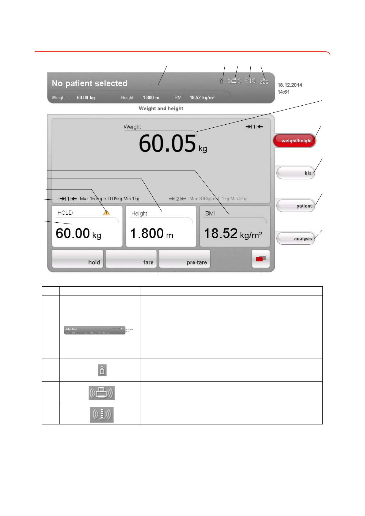
3.2 Symbols in the start display
A
C
I
J
E
D
K
L
M
F
O
Q
N
G
H
P
B
Symbol Meaning
A
B
C
D
Header, remains unchanged in all menu levels and tabs. The following
data are displayed:
•patient data
-name
-weight
-height
-BMI
• data connections
•date/time
Login symbol:
indicates whether the user is logged in to a seca patient database (user
PIN required)
Printer symbol:
indicates whether the print function of the seca 115 PC software is
available
Measuring rod symbol:
indicates whether there is a connection to a seca 360° stadiometer
12 •
English
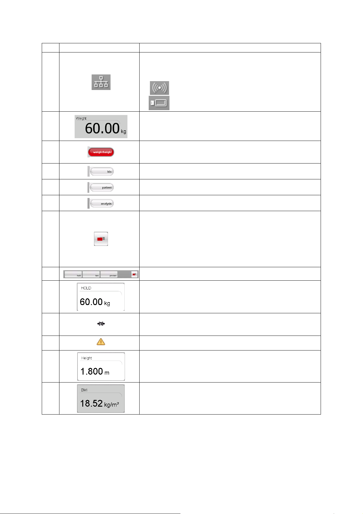
Symbol Meaning
Data connection symbol:
indicates the current type of connection to the seca patient database (in
this case Ethernet connection between PC and
Additional possible connection types:
seca 115
E
• seca 360° wireless connection between PC and seca 115
• USB memory stick connected to device
G
H
K
M
F
I
J
L
Weight display
weight/height tab
Automatically active after device is switched on
For determining weight and height of patient
bia tab
For performing a bioimpedance analysis
patient tab
For assigning the measured results to a seca patient file
evaluation tab
For evaluating measured results and analysis results and for saving data
menu changeover button
Appears if secondary menu is available
• Primary menu: contains the functions commonly used in the current
context
• Secondary menu, contains the following functions:
settings
-
- print
- save
Menu bar with context-dependent buttons and menu changeover button
Hold value display
Weighing range currently in use:
N
O
P
Q
• 1: finer divisions of the weight display at a lower capacity
• 2: maximum capacity
Non-verifiable function is active (for verified models only)
Display of patient's height
• Can be entered manually
• Can be received by a seca 360° stadiometer
Display of patient's body mass index (BMI)
Calculated automatically as soon as a weight is available and a height
value has been received or entered
Device overview • 13

3.3 Color symbols and other controls
Control/display Symbol Meaning
LED white: device on
ON/OFF button
Data connection
symbol, in this case
seca 360° wireless link
between a PC and
seca 115
Login symbol: log in to a
seca patient database
Tab
LED green: device on standby
LED off: device off
White: connection available
Red: data being transmitted on the available connection
Gray: connection not available
White: user is logged in
Gray: no user logged in
White: tab not selected
Red: tab selected
Light gray: function available
Buttons
Electrode indicator (for
bioimpedance
measurement)
Drop-down triangles
Checkboxes
Gray: button pressed, function selected
Dark gray: function not available
Red: contact poor
Green: contact good
Gray: function available
Light gray: function not available
No tick: function deactivated
Tick: function activated
14 •
English
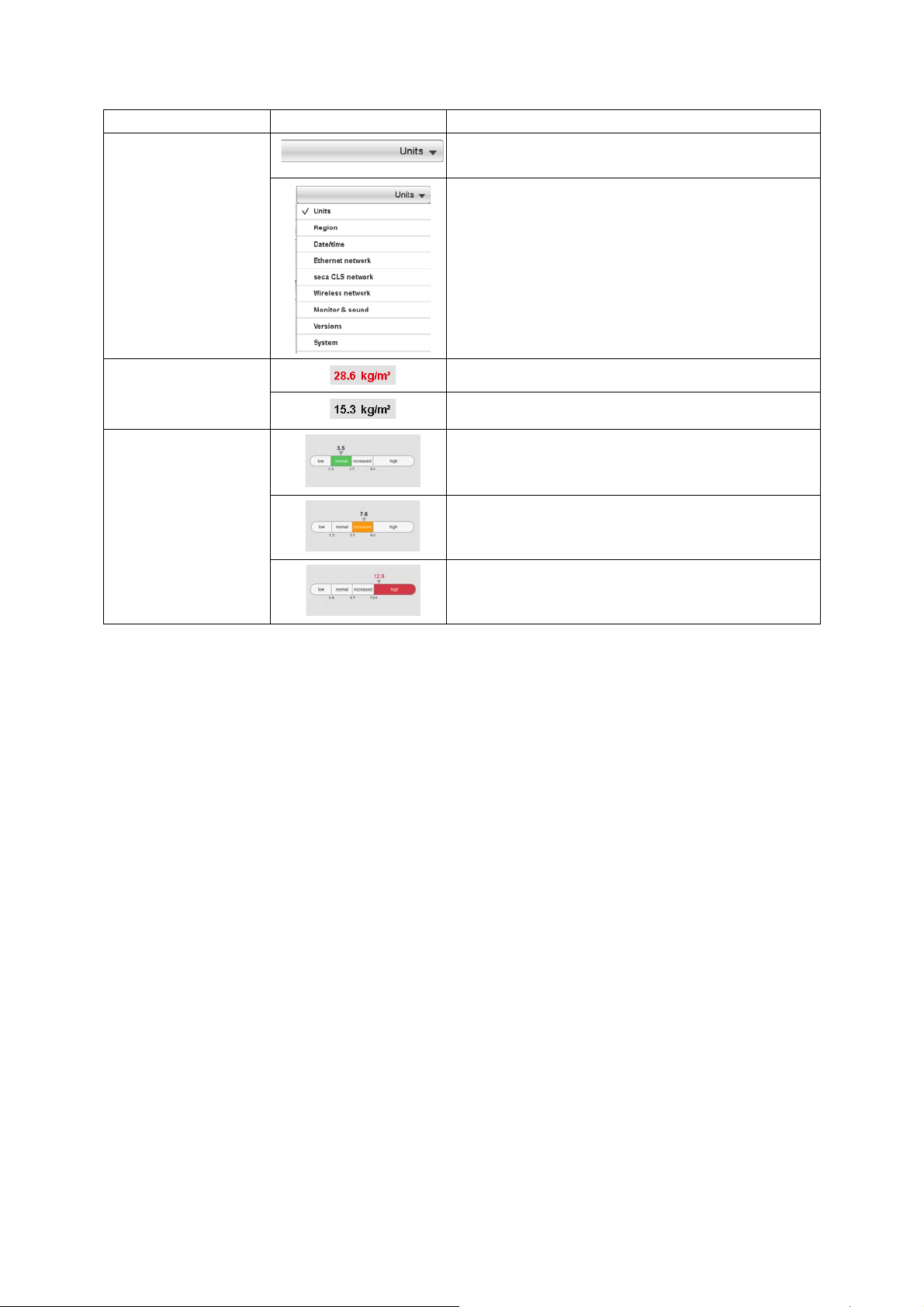
Control/display Symbol Meaning
Selected function
Drop-down menu
Drop-down menu open
Red text: value outside normal range
Text color
Gray text: value within normal range
Green: Value within normal range
Display, evaluation
Orange: Value slightly elevated
Red: Value outside normal range
Device overview • 15
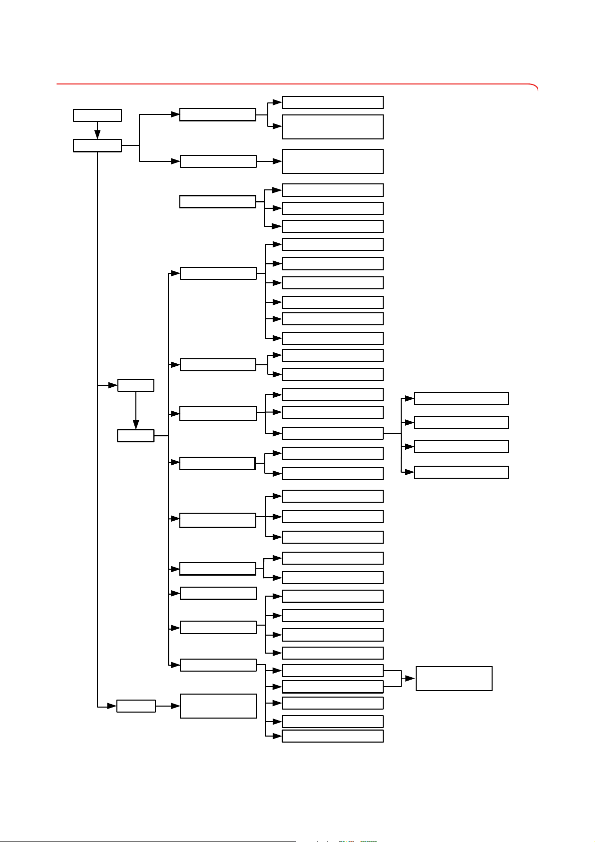
3.4 Menu structure
System
Unit changeover
Ethernet network
seca CLS network
Wireless network
Monitor & sound
Change GAL value
Calibrate device
Set the quality check
Read off calibration counter
Show/hide default module selection
before BIA measurement
settings
user
Activate/deactivate modules
for default module selection
Default module selection
Set weight units
Set energy units
Set height unit
Set setup location
Set language
Region
Set date format
Set time format
Set name format
Set name hyphen
Set date
Date/time
Set time
admin
Enter IP address
View current settings
Activate/deactivate DHCP
Set up Ethernet
Enter netmask
admin PIN
Enter domain name server
Enter IP address
Enter default gateway
Enter port
Activate/deactivate wireless module
Set up wireless group
View wireless devices
Set display brightness
Set volume
Export system log file
Versions
Change administrator PIN
System
Calibrate touchscreen display
Reset admin settings
Service: primary functions
For authorized service
engineers only
For authorized service
engineers only
service
Update device software
Export/import settings
16 •
English
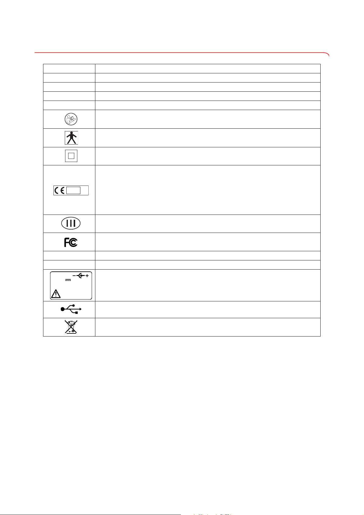
3.5 Identification on the device and the type plate
M
16
0102
0123
use compatible
seca adapter only
12 V
min. 1,25 A
Text/symbol Meaning
Mod Model number
Approval Type Type designation of design approval (
S/N Serial number, consecutive
ProdID Product identification number, consecutive
Follow instructions for use
Medical electrical device, type BF
Insulated device, protection class II
Device complies with EC standards and directives.
M: Conformity label according to Directive 2014/31/EU governing non-automatic weighing
•
instruments (verified models)
16: (Example: 2016) Year in which the declaration of conformity was completed and the CE
•
symbol was applied (verified model)
0102: Notified body metrology (verified models)
•
• 0123: Notified body medical products
Class III scale to Directive 2014/31/EU and OIML R76-1 (verified models)
seca 515 only)
FCC symbol (USA)
FCC ID For USA: device license number from the Federal Communications Commission (FCC)
IC For Canada: device license number from Industry Canada
Operate device only with an original seca power pack
USB interface
Do not dispose of device with household waste
Device overview • 17
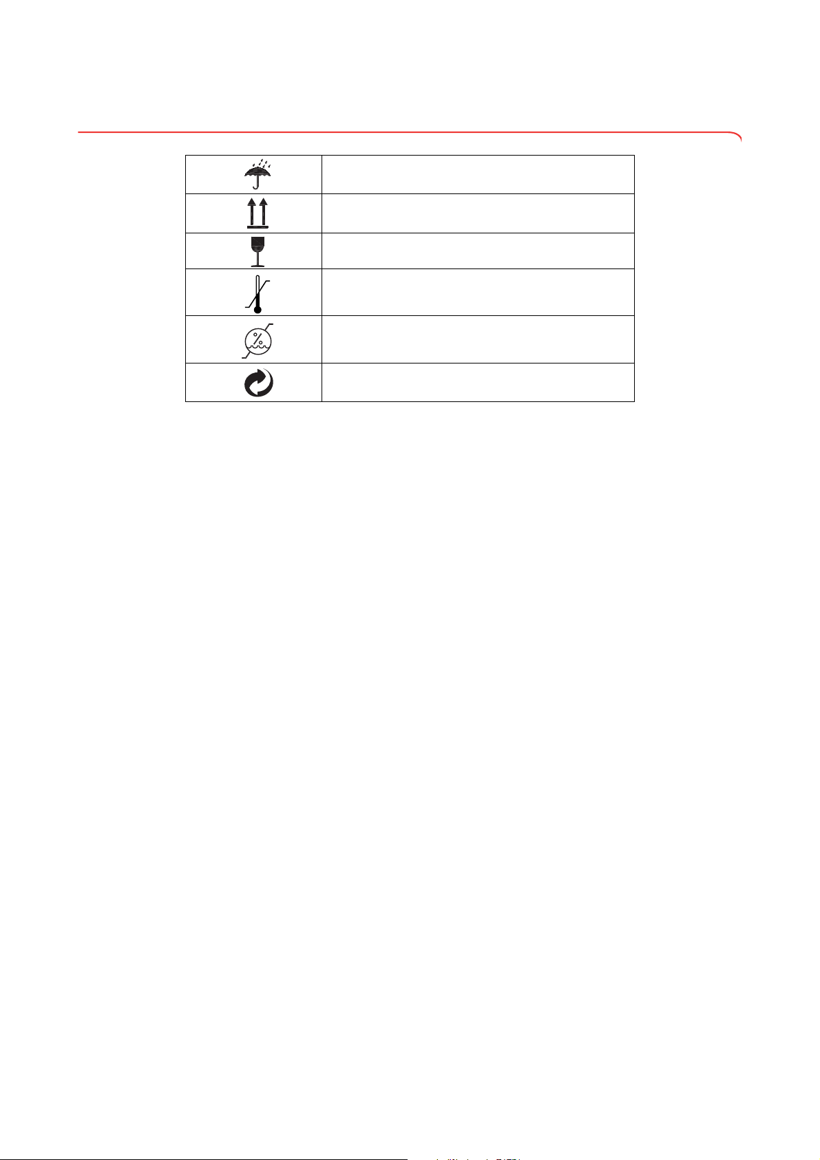
3.6 Identification on the packaging
Protect from wet
Arrows point to top of product
Transport and store upright
Fragile
Do not throw or drop
Permitted min. and max. temperature for transport and
storage
Permitted min. and max. humidity for transport and
storage
Packaging can be disposed of via recycling programs
18 •

English
4. MAKING THE DEVICE OPERATIONAL
seca 115
User Docs
seca
515/514
a b
c
ghf
e
d
4.1 Scope of delivery
No. Component Pcs.
medical Body Composition Analyzer 1
a
Power pack 1
b
DVD with seca 115 PC software and license for a permanent workplace 1
c
DVD with user documentation in PDF format:
• Instructions for Use for Physicians and Assistants
d
• Administrator Manual
• additional information
Instructions for Use for Physicians and Assistants, hard copy 1
e
seca 360° wireless USB adapter 456 1
f
seca USB memory stick, 2 GB, initialized (USB PIN: 0000) 1
g
Ethernet cable (1.5 m) for connecting to a TCP/IP network 1
h
1
Making the device operational • 19

4.2 Establishing power supply
4.3 Setting up the device
WARNING!
Using the wrong power packs may cause bodily injury or damage to
the device
Conventional power packs may deliver a higher voltage than is indicated on them. The device may overheat, catch fire, melt or shortcircuit.
► Use only the original seca power pack as contained in the scope of
delivery and listed in the section entitled “Spare parts” on page 56.
The connection for the power pack is located on the underside of the
weighing platform. To establish the power supply, proceed as outlined below.
1. Insert the plug required for your power supply into the power pack.
2. Tilt the device forward.
3. Insert the device connector of the power pack into the connector socket
of the device.
4. Carefully return the device to an upright position.
5. Plug the power pack into a power supply socket.
The device is fully assembled upon delivery.
ATTENTION!
Incorrect measurement due to force shunt
If the device and its housing are in contact with something, e.g. due to
an uneven or soft floor covering, weight will not be measured correctly.
► Set up the device so that only its foot screws are in contact with the
floor.
1. Place the device on a firm, level surface.
ATTENTION!
Incorrect alignment may cause incorrect measurements
The spirit level is very sensitive. Additional weights, such as towels,
can result in incorrect scale alignment.
► Align the device only without a load on it.
20 •
2. Level the device by turning the foot screws.
The air bubble in the spirit level must be located in the center of the circle.

English
4.4 Operating the device in a PC network
The device does not have “on-board” patient and user administration. If you
wish to administer seca patient files and user accounts, the device must be
connected to a PC on which the
the following connection options:
• network connection via
• indirect connection via USB memory stick
seca 115 software and the device itself should only be installed and
The
configured by experienced PC administrators or hospital technicians.
ATTENTION!
Loss of data
Incorrect installation or incorrect changes to the installation can lead
to loss of data and, as a result, to misdiagnoses.
► Make sure the installation or changes to the installation are carried
out by an experienced administrator or hospital technician.
seca 115 PC software is installed. You have
seca 360° wireless network or Ethernet
Connecting the network via
Ethernet or seca 360°
wireless
network
If the device is to be directly integrated in a PC network, the steps below are
necessary.
• Install the
• Administer the
• Configure the
seca 115 PC software on the PC
seca 115 PC software
seca 515/514
• Set up Ethernet or seca wireless network
Details on the steps mentioned can be found in the section entitled “Configuring the device” from page 28 and in the Administrator Manual for the
seca 115
PC software.
seca 115
seca 115
Making the device operational • 21

Print If the device is connected to the seca 115PC software via seca 360° wireless
seca 115
Printer
Indirect connection via USB
memory stick
network or Ethernet, you can use the special print function of the seca 115 PC
software and print out detailed results reports on a PC printer.
The print function is a component of the so-called seca mediator service, a
function module of the
seca 115 PC software. The seca mediator service
performs the tasks outlined below.
• Calculating bioimpedance analysis from the raw data for impedance of the
device
• Graphical processing of the bioimpedance analysis
• Collation and printing of a detailed results report
Printing of a results report can be started directly from the device. The raw
data for impedance are sent to the
seca 115 PC software and the seca
mediator service starts automatically.
In order to be able to use this function via Ethernet, the device must be incorporated in a seca CLS network. Details on this can be found in the section
entitled “Setting up seca CLS network (via Ethernet only)” from page 38 and
in the Administrator Manual for the
seca 115 PC software.
If the device is not to be integrated directly in a PC network, you can create
seca patient files and save measurements on the seca USB memory stick
supplied.
The seca USB memory stick is supplied initialized, which means that it contains a seca patient database and is secured with an initial USB PIN (0000).
If you wish to use additional USB memory sticks (seca original accessories
recommended), these must also be initialized before patient files can be
saved on them. Details on this can be found in the Administrator Manual for
seca 115 PC software.
the
You can synchronize the seca patient database on the USB memory stick
with the seca patient database of the
seca 115 PC software.
The steps below are necessary.
• Install the
• Administer the
• Configure the
seca 115 PC software on the PC
seca 115 PC software
seca 515/514
• If already available, load seca patient files from the seca 115 PC software
onto the USB memory stick
Details on the steps mentioned can be found in the section entitled “Configuring the device” from page 28 and in the Administrator Manual for the
seca 115
PC software.
22 •

English
4.5 Operation using a seca 360° stadiometer
seca 115
As an alternative to manual entry, you can use a seca 360° stadiometer to
determine height and transfer the height to the device via
network.
Height is taken into account when analyzing the bioimpedance measurement.
If the device is connected to the
together with the other measured results in a seca patient file and transmitted
seca 115 PC software.
to the
The steps below are necessary.
• Setting up
• Setting up
• Setting up the seca 360° wireless network
Details on the steps mentioned can be found in the section entitled “Configuring the device” from page 28 and in the instructions for use for the
stadiometer and in the Administrator Manual for the seca 115 PC software.
seca 515/514 and establishing a power supply
seca 360° stadiometer
seca 360° wireless
seca 115 PC software, height is recorded
seca 360°
Making the device operational • 23

5. OPERATING CONCEPT
max. 180°!
max. 180°!
5.1 Swiveling the touchscreen display
The touchscreen display of the device can be swiveled. As a result, it can be
perfectly positioned for every application.
► Swivel the touchscreen display so that is convenient for you to operate
and read.
ATTENTION!
Damage to device
The swivel mechanism of the touchscreen display has an end stop.
Do not attempt to swivel the touchscreen display by more than 180°.
This will lead to mechanical damage to the housing and the internal
cabling.
► In every direction, only rotate the touchscreen display as far as the
5.2 Switch on device
The device is switched on using the ON/OFF button. During the switch-on
procedure, the device performs a self-test. The self-test may take several
seconds.
1. Press the ON/OFF button briefly.
The LED of the button briefly turns white.
The internal PC of the device boots up. This takes several seconds.
The weighing function is available when the LED of the button is
permanently white and the
2. Press the bia tab in the display.
The bioimpedance analysis function is available if the
message is no longer displayed and the Module selection dialog window
appears.
The device is ready for operation.
end stop.
weight/height tab is shown in the display.
Self-test active
5.3 Selecting functions
Functions can be selected using the following elements of the touchscreen
display:
•tabs
• buttons
•drop-down menus
•checkboxes
► To select a function, press directly on the corresponding display element
(in this case tab, buttons).
24 •

English
5.4 Selecting extended functions
Functions commonly used in a certain context are accessible in the primary
menu. Additional functions are accessible in the secondary menu.
1. Press the
2. Press the
5.5 Entering text
Text is entered via a computer keyboard shown on the touchscreen display.
NOTE:
The assignment of functions to the primary and secondary menus is
specified at the factory and cannot be changed.
Menu changeover button.
The secondary menu is displayed.
Menu changeover button again.
The functions in the primary menu are shown again.
1. Press an input field.
If the field is intended to have text entered in it, a computer keyboard
appears in the display.
2. Type in the desired text.
3. Press the Enter key on the keyboard.
The entry is accepted.
Operating concept • 25

5.6 Entering numbers
Numbers are entered via a computer numerical keypad shown in the
touchscreen display.
.
1. Press an input field.
If the field is intended to have numbers entered in it, a numerical keypad
appears in the display.
2. Type in the desired number.
3. Press the Enter key on the numerical keypad.
The entry is accepted.
5.7 Measuring procedure
The operating concept is based on the typical measuring procedure outlined
below.
• Measure weight and height
• Perform a bioimpedance measurement
• Assign measurements to a seca patient file
• Evaluate measured results
• Save measuring procedure
The order of the tabs on the touchscreen display follows this sequence. It is
possible to operate in a different order.
You can find additional information on the measurement procedure in the
Instructions for Use for Physicians and Assistants.
26 •

English
5.8 Automatic standby
5.9 Switching off the device
The device automatically switches to standby if there are no entries on the
device for 5 minutes. This has the following effects:
• measured results and settings which have not been saved are lost.
• the user currently logged in is automatically logged out.
• the LED of the ON/OFF button is green.
• the touchscreen display goes out.
WARNING!
Electric shock
The device cannot be de-energized by pressing the ON/OFF button.
► Always take out the power supply plug if the device needs to be
de-energized - e.g. for a hygiene treatment.
► Press the ON/OFF button briefly.
The LED of the button turns green. The touchscreen display goes out.
The device is on standby.
► Press and hold the ON/OFF button
The LED of the button goes out. The touchscreen display goes out. The
device is switched off.
NOTE:
When switching on again from standby, the
weight/height tab is active
immediately. When switching a device which has been switched off
back on again, the internal PC boots up again. This takes several
seconds.
Operating concept • 27

6. CONFIGURING THE DEVICE
6.1 Adapting the default module selection for bioimpedance analysis
The default module selection determines which evaluation modules are
considered during a bioimpedance analysis.
The device is factory-set so that when the
module selection
dialog window appears and all evaluation modules are activated. This way, the module selection can be verified before each measurement and, if necessary, adapted to suit the individual measurement.
The device can be configured in such a way that the
dialog window does not appear if the bia tab is activated. You can also create
an in-house default module selection.
bia tab is activated, the Default
Default module selection
Showing/hiding default module
selection
In order to determine whether or not the Default module selection dialog
window is displayed before each bioimpedance analysis, proceed as outlined
below.
1. Press the
menu changeover button.
The secondary menu is displayed.
2. Press the
The
settings button.
User menu appears.
The current setting is displayed (button appears gray = pressed).
3. Press the desired setting.
–
no: default module selection is active. It is displayed before every
bioimpedance analysis and can be adapted to suit the measurement in question.
–
yes: default module selection is active but is not displayed before
the bioimpedance analysis. The default module selection can only
be adapted in the
4. Press the
apply button.
settings menu.
The module selection is saved and will be available from the next
bioimpedance analysis.
28 •

English
Creating default module selection To create an in-house default module selection, proceed as outlined below.
1. Press the
The secondary menu is displayed.
2. Press the
The
3. Press the drop-down menu.
The drop-down menu opens.
4. Press the
menu changeover button.
settings button.
User menu appears.
Default module selection menu element.
The current module selection is displayed.
The
Raw data for impedance evaluation module is deactivated at the fac-
tory. Activation/deactivation of the Raw data for impedance, Energy and
Health risk evaluation modules affects the course of the bioimpedance
measurement as outlined in the table below.
Setting
Evaluation module
Energy
Health risk
Raw data for
impedance
• = activated,
- = deactivated
•
-
•
-
-
•
Physical activity level (PAL) is
interrogated
No interrogation of physical
activity level (PAL)
Waist circumference (WC) is
interrogated
No interrogation of waist
circumference (WC)
Duration of measurement:
max. 17 s
Duration of measurement:
max. 75 s
Raw data for impedance available
Effect
a
for 19 frequencies
a.Interrogation of PAL and WC in the Module-specific entries dialog win-
dow. Dialog window is skipped if the Energy and Health risk evaluation
modules are deactivated.
5. Press all modules you wish to deactivate.
The tick in the checkbox is no longer displayed.
NOTE:
Press on a module again to reactivate it.
Configuring the device • 29

6. Press the apply button.
The module selection is saved and will be available from the next
bioimpedance analysis.
NOTE:
To exit the dialog window without saving, press the
the most recently active tab (red, in this case
bia). The most recently
active tab is active again.
6.2 Administering user accounts and access rights
The device has no “on-board” user administration. User accounts can only be
set up and edited in the seca 115 PC software.
When setting up user accounts, different PINs and passwords must be
assigned for the usage and administration of the system. The table below
provides an overview.
Password/PIN Use Source Change in
seca 515/514:
User PIN
USB PIN
Admin PIN
User password
Admin password
access to seca 115 patient database:
•Ethernet
• seca wireless network
• USB memory stick
seca 515/514:
access to
seca 115 patient database:
• USB memory stick
seca 515/514:
device configuration
seca 115:
administering measurements and
patient data
seca 115:
administration of PC software
Automatic assignment by
admin when setting up a
seca 115 user account
Initial USB PIN (0000) is supplied with the USB stick
seca 115
seca 115
Initial admin PIN (00000) is
supplied with the
514
seca 515/
seca 515/514
Created by Admin in seca 115 seca 115
Initial Admin password is supplied with the seca 115
seca 115
cancel button or
Additional information on user administration and access rights can be found
in the Administrator Manual for the
6.3 Calling up the Administrator menu
1. Press the menu changeover button.
The secondary menu is displayed.
2. Press the
The secondary menu
3. Press the
seca analytics 115 PC software.
settings button.
settings is displayed.
admin button.
30 •

English
The password request appears.
4. Enter your administrator PIN (factory setting: “00000”).
5. Press the Enter key on the numerical keypad.
The entry is accepted.
The
admin dialog window appears.
6. Press the drop-down menu.
The drop-down menu opens.
7. In the drop-down menu, select the desired menu elements as described
in the sections below.
Configuring the device • 31

6.4 Making default settings
Setting units of measurement
1. Call up the Administrator menu.
The
Units dialog window is active.
The current settings for weight, energy and height are displayed (button
gray = pressed).
2. Press the desired settings.
CAUTION!
Hazard to patient
To prevent misinterpretations, measured results for medical purposes
may only be displayed and used in SI units (weight: kilograms, height:
meters). Some devices have the option of displaying measured results
in different units. This is purely an additional function.
► Only use measurements in SI units.
► The user takes sole responsibility for the use of measured results in
non-SI units.
3. Press the
apply button.
The new settings are active.
Making regional settings 1. Call up the Administrator menu.
2. In the drop-down menu, select the
Region dialog window appears.
The
3. In the
Setup location drop-down menu, select the country in which you
are operating the device.
Region element.
32 •

English
NOTE:
The selection of the setup location has an impact on which references
the device uses to evaluate measured results. For information on the
topic of references, see the Instructions for Use for Physicians and
Assistants.
4. In the
Dialogue language drop-down menu, select the desired language.
5. In the Date format drop-down menu, select the desired date format.
6. In the Time format drop-down menu, select the desired time format.
Configuring the device • 33

7. In the Name format drop-down menu, select the desired sequence for the
patient's name and surname.
Patients' first names and surnames will be displayed in the device's lists
and dialog windows in accordance with the sequence you select.
8. In the
Name hyphen drop-down menu, select the desired hyphenation.
34 •
In lists and dialog fields, patients' first names and surnames will be
separated by the selected character.
ATTENTION!
Loss of data, incorrect assignment of measurements
The settings for name sequence and name hyphens are not automatically synchronized with the settings in the PC software. If the settings
do not match, patients may be confused and measurements assigned
to the incorrect seca patient file.
► Ensure that the same settings for name sequence and name hy-
phen are made both on the device and in the PC software.

English
9. Press the apply button.
10. Switch the device off and back on again.
The settings are adopted.
Setting the date and time 1. Call up the Administrator menu.
2. In the drop-down menu, select the
3. Press the field for the value you wish to set:
–
Date
Time
–
The numerical keypad appears.
4. Enter the current value.
5. Press the Enter key on the numerical keypad.
The set value appears in the corresponding field
6. Repeat steps 4. and 5. for every other value you wish to change.
7. If you have selected the time format
am / pm setting matches actual time.
ATTENTION!
Loss of data, misinterpretation of measurements
The settings for date and time are not automatically synchronized with
the settings in the PC software. If the settings do not match, different
date and time details may lead to measurements being misinterpreted.
► Ensure that the same settings for date and time are made both on
the device and in the PC software.
8. Press the
9. Switch the device off and back on again.
The settings are adopted.
apply button.
Date/time element.
12 h under Region, ensure that the
Configuring the device • 35

Setting display brightness and
volume
1. Call up the Administrator menu.
2. In the drop-down menu, select the
Monitor & sound dialog window appears.
The
Monitor & sound element.
3. Press the slide control of the desired variable and move it to the left or to
the right.
Variable Left Right
Brightness Dark (20 %) Light (100 %)
Volume Quiet (0 %) Loud (100 %)
4. Press the apply button.
The new settings are active.
6.5 Setting up the network
Requirements • seca 115 PC software installed on a PC
Network services The following table shows which network services are installed in combination
• For Ethernet network: PC with network card and Ethernet interface
seca 360° wireless network: PC with connected
•For
seca 360° wireless USB adapter 456
NOTE:
► To use the network functions, observe the user documentation for
the
seca 115 PC software.
► If a USB memory stick is connected to the device, you can no longer
with the
access data of the
seca 360° wireless network.
seca 115 PC software. Depending on the type of network envisaged,
seca 115 PC software via Ethernet oder
the links to these services need to be set up on the device (• = necessary,
- = not necessary).
seca 360°
wireless
Ethernet
network
Set up wireless network •
Set up Ethernet connection
Set up link to CLS server and
seca mediator service
a.seca mediator service available for seca 515/514 from SW version 1.1 and
for seca 115 from SW version 1.4
a
-
-
-
•
•
36 •

English
NOTE:
► It is possible to combine network cards. For example, you can link
a
seca 360° stadiometer to the device via seca 360° wireless net-
work and link the device itself to a PC on which the
seca 115 PC
software is installed via Ethernet.
► Details on setting up the individual services can be found on the
pages which follow.
Network-dependent functions The following table shows the functions of the device and of the seca 115 PC
software which require a network connection and states in what kind of network these functions are available (• = available,
Height transmitted to the device wirelessly
Start the print function of the
seca 115 PC software directly on the
a
device
Send individual seca patient file from
seca 115 PC software to the
the
device
Search seca patient files from the
device in the patient database of the
seca 115 PC software
Save seca patient files from the
device in the patient database of the
seca 115
a.Available for seca 515/514 from SW version 1.1 and for seca 115 from
SW
version 1.4
- = not available):
seca 360°
wireless
Ethernet
network
•
- •
-
-
•
••
••
Integrate device in an Ethernet
network
seca 115
NOTE:
Information about using the network-dependent functions can be
found in the “Instructions for Use for Physicians and Assistants” for
this device and for the seca 115 PC software.
1. Create the hardware link between the device and the network using an
Ethernet cable.
2. Call up the administrator menu on the device.
3. In the drop-down menu, select the Ethernet network element.
Configuring the device • 37

4. In the DHCP line, press the setting to suit your network.
– No DHCP server in the network: off, proceed with step 5.
– DHCP server in the network: on, proceed with step 7.
5. Press the
set up button.
The dialog window for setting up the Ethernet network appears.
6. Make the applicable settings for your network.
7. Press the save button.
The new settings are active.
Setting up seca CLS network (via
Ethernet only)
38 •
To enable communication between the device and the seca 115 PC software
via Ethernet, you must link the device to the CLS server and the seca mediator service. CLS server and seca mediator service are communication modules of the
seca 115 PC software.
Once the link to the two communication modules has been set up, the
following functions can be used directly from the device:
• accessing the seca patient database of the
seca 115 PC software
• printing out a detailed results report directly from the device on a PC printer
(the printer is selected in the
seca 115 PC software does not need to be started for this. Only the PC
The
seca 115 PC software)
on which the two communication modules and the seca patient database are
installed must be switched on.

English
Netzwerk-Drucker
Network printer
seca 115 client (optional)
CLS server
seca mediator service
seca patient database
IP address 192.168.2.12
Port: 60667
seca 115 client
seca 115 client
seca 115 client
sec 115 Client
seca 115 Client (optional)
CLS-Server
seca mediator service
seca Patientendatenbank
IP-Adresse: 192.168.2.12
seca 115 Client
seca 115 Client
Port: 60667
The two communication modules and the seca patient database are installed
automatically when you select the options
seca 115 PC software.
the
Server or Complete for installing
NOTE:
Also observe the Administrator Manual for the
seca 115 PC software.
The CLS server and seca mediator service are addressed via the same IP
address and the same port. To set up this link, proceed as outlined below.
1. Call up the administrator menu on the device.
2. In the drop-down menu, select the seca CLS network element.
The current settings are displayed.
3. In the
IP address line, enter the appropriate IP address.
Configuration IP address
seca 115 PC software as a client/
server solution
seca 115
PC software as a stand-
alone solution
4. In the
port line, enter the line “n+100” (n = port for the PC selected under
3., default: 60667).
5. Press the apply button.
The new settings are active.
The IP address of the PC on which
the seca 115 PC software was
installed with the options Server or
Complete
IP address of the PC workstation
Configuring the device • 39

Setting up the seca 360° wireless
network
Use the wireless network function to link other seca 360° devices, e.g.
stadiometers, to the seca 515/514 device wirelessly.
NOTE:
► If you wish to link t he device t o t he seca 115 PC software, set up the
seca wireless network from the PC software. Further information
can be found in the Administrator Manual for the PC software.
► For faster data transmission, we recommend connecting the device
via Ethernet to the PC on which the
seca 115 PC software is in-
stalled. For information about this, see this document from page 37
and the Administrator Manual for the
► A description of the functional principle of the seca wireless network
seca 115 PC software.
can be found in the section entitled “Technical information” from
page 56.
To set up a seca 360° wireless network, proceed as outlined below.
1. Ensure that all devices you wish to connect to the
seca 515/514 device are
switched off.
2. Call up the administrator menu on the
3. In the pull-down menu, select the
seca 515/514 device.
wireless network element.
The wireless network dialog window appears.
4. In the
send & receive line, press the on button.
5. In the wireless group line, press the set up button.
6. Press the desired wireless group (in this case wireless group “0”).
The program will suggest three channels.
40 •

English
ATTENTION!
Incorrect device assignment and faulty data transfer
You can select channel numbers other than those suggested by the
system. This may cause devices to be assigned to incorrect wireless
groups, resulting in unreliable data transmission.
► Check that the channel numbers are not being used for the other
two wireless groups.
► Make sure that the channel numbers are at least 30 apart from one
another.
7. Click on
next.
The software will wait for signals from other seca 360° devices in range.
8. Switch on all devices you wish to incorporate in a wireless group.
When the devices are detected, a beep will be heard.
Detected devices (in this case
seca 360° stadiometer) will be shown in the
touchscreen display. The corresponding symbols in the header appear
white.
9. Click on exit.
Configuring the device • 41

Detected devices are shown on the touchscreen display.
10. Click on back.
The
wireless network dialog window appears.
The seca wireless network for wireless group 0 is set up.
11. Click on
The
apply.
wireless network dialog window closes.
Viewing wireless devices 1. In the wireless devices line, press the View button.
All detected devices are displayed.
2. Click on
The
3. Click on
The
back.
wireless network start screen is displayed again.
apply.
wireless network dialog window closes.
42 •

English
6.6 System data
Entry in “scale log book” line
1. 140301 1.0 14.2 02.01.2005
Serial number
Software identification
Software versions of
parts of the program
which have to be verified
Date device was
updated
Viewing versions 1. Call up the Administrator menu.
2. Press the drop-down menu.
The drop-down menu opens.
3. Press the
The
versions menu element.
versions dialog window appears.
Viewing software versions
The versions of the individual software components active in the device are
displayed in the versions dialog window.
1. Read off the versions.
2. To exit the
The
versions dialog window, click on exit.
versions dialog window closes.
Making system settings 1. Call up the Administrator menu.
Viewing scale logbook
You can view versions for device software components which are relevant for
verification in the scale log book line of the versions dialog window. The
current entry is displayed as soon as the
versions dialog window opens.
1. Read off the current entry.
2. To view the sequence of versions, press the
history button.
– Press once: previous entry is displayed
– Press several times: all entries are displayed consecutively.
3. Read off the versions.
NOTE:
The
history function is purely for information. It is not possible to
reactivate older versions.
4. To exit the
5. The
versions dialog window, click on exit.
versions dialog window closes.
2. Press the drop-down menu.
The drop-down menu opens.
3. Press the
system menu element.
Configuring the device • 43

The system dialog window appears.
Exporting the system log file
You can export the system log file at regular intervals. To do so, you require a
USB memory stick with the following characteristics:
• file system: FAT16
• no old log files on the stick
To export the system log file, proceed as outlined below.
1. Connect the empty USB memory stick to the USB port of the
touchscreen display.
2. In the
system dialog window, press the Export button.
44 •
3. Wait until the
Export completed message appears.
4. Analyze and archive the system log file in line with your institution's policy.
5. Delete the system log file from the USB memory stick.
The memory stick is ready for the next export.
Changing administrator PIN
ATTENTION!
Malfunction due to incorrect configuration
Every user who knows the administrator PIN can access the
administrator menu and administer the system.
► Upon initial use, assign a new administrator PIN, in order to prevent
access by persons without sufficient expertise.
► Only give the new administrator PIN to persons with sufficient
expertise in configuring the system.
To change the administrator PIN, proceed as outlined below.
1. Call up the Administrator menu.

English
2. In the drop-down menu, select the system element.
3. In the
system dialog window, press the Change button in the
administrator PIN line.
The numerical keypad appears.
4. Enter the previous administrator PIN (factory setting: 00000).
5. Press the Enter key on the numerical keypad.
The entry is accepted.
6. Enter the new administrator PIN.
7. Press the Enter key on the numerical keypad.
The entry is accepted.
8. Enter the new administrator PIN again.
9. Press the Enter key on the numerical keypad.
The entry is accepted.
The message
Administrator PIN changed appears.
10. Switch the device off and back on again.
The new administrator PIN is active.
Calibrating touchscreen display
If the device has a delayed reaction or does not react at all to the controls in
the touchscreen display being pressed, you can calibrate the touchscreen
display. To do so, proceed as outlined below.
1. Call up the Administrator menu.
2. In the drop-down menu, select the
3. In the
system dialog window, press the Calibrate button in the
touchscreen display line.
system element.
Configuring the device • 45

The calibration display appears.
4. Press and hold the cross symbol.
The cross symbol changes position.
5. Press and hold the cross symbol.
The cross symbol changes position again
6. Repeat steps 4. and 5. until the cross symbol is no longer displayed.
The touchscreen display is calibrated.
7. Press the empty touchscreen display.
The
system dialog window is shown again.
Restoring factory settings
You can restore the factory settings for the functions below.
Function Factory setting
Setup location Others
Language English
Date format mm.dd.yyyy
Time format 24 h
Volume 50 %
Pre-tare (Pt) 0 kg
Height 0.0 cm
Brightness of display (back)lighting 100 %
Wireless module Off
Administrator PIN 00000
CLS server and seca mediator service:
• IP address
•port
0.0.0.0
60767
DHCP yes
Module selection for BIA measurement:
• display prior to BIA measurement
• active modules
raw data for impedance
yes
deactivated
1. Call up the Administrator menu.
2. In the drop-down menu, select the
system element.
3. In the system dialog window, press the Reset button in the admin settings
line.
46 •

English
Factory settings will be restored.
The message Factory settings successfully restored. appears.
4. Press the
The
next button.
system dialog window is shown again.
Configuring the device • 47

Using service functions The Service: primary functions dialog window contains functions your service
engineer uses frequently.
The following functions may only be used by your service engineer. The
functions are protected by a special access code (SEED).
• Correcting GAL value
• Readjusting the device
The functions below can also be used by you as administrator. To do so,
proceed as described on the pages which follow.
• Setting the quality check for the BIA
• Updating device software
• Exporting system settings
• Importing system settings
The functions in this dialog window are included as extras with other service
functions in the
service menu. Contact your service engineer if required.
Updating device software
This function allows you to install a software update on your device. We
provide software updates on our website for you to download.
NOTE:
The firmware of the weight recording module
cannot be updated
using this function.
To install a software update, proceed as outlined below.
1. Load the software update onto a USB memory stick.
2. In the
Service: primary functions dialog window, press the update button.
Security information about the software update appears on the screen.
48 •

English
3. Read the security information carefully.
4. Press the
update button.
The update process starts.
5. Follow the instructions on screen.
Exporting system settings
You can use this function to export and archive all system settings for the
device in order to reload them after a software update, for example, or in
order to configure other devices in the same way. To do so, proceed as
outlined below.
1. Connect the USB memory stick to the USB port of the touchscreen
display.
2. In the
Service: primary functions dialog window, press the Export button.
All system settings are loaded onto the USB memory stick.
3. Archive the system settings in line with your institution's policy.
Importing system settings
You can use this function to reload archived system settings for the device
after a software update, for example. If several devices are in operation, you
can use this function to ensure that the system settings are identical on all
devices. To do so, proceed as outlined below.
1. Load the archived system settings onto a USB memory stick.
2. Connect the USB memory stick to the USB port of the touchscreen
display.
3. In the
Service: primary functions dialog window, press the import button.
Configuring the device • 49

All system settings are loaded onto the device.
4. Follow the instructions on screen.
6.7 Saving settings
Applying settings 1. Press the apply button.
The
Save successful dialog window appears.
2. Press the
The administrator menu appears on the display again.
You can make additional settings in the administrator menu or exit the
administrator menu as described in the section entitled “
administrator menu
Exiting the administrator menu 1. Press the exit button.
The
Unsaved changes dialog window appears.
2. Press the desired button:
–
yes: the changes will be saved. The settings\User menu appears in
the display again.
–
no: the changes will not be saved. The settings\User menu appears
in the display again.
3. Press the
The most recently active tab is active again.
The device is ready to measure.
next button.
Exiting the
”.
exit button.
50 •

English
7. TROUBLESHOOTING
7.1 Power supply and display
Problem Cause Remedy
Device cannot be switched on
Touchscreen display remains
dark
Touchscreen display not
reacting
Image on touchscreen display
faulty
7.2 Height and weight
Problem Cause Remedy
0.00 does not appear before
weighing
The STOP message appears Maximum load exceeded Remove the load from the device
TEMP message appears
The message ER11 appears
The message ER12 appears
The message ER16 appears
No power supply Check whether power is being supplied
Power pack faulty Replace power pack with original part
• Touch the touchscreen display
Device on standby
• Press the on/off button
• Place a load on the device
Device is not switched on Switch on device
No power supply Check whether power is being supplied
Touchscreen display faulty Inform seca service
Device in undefined state following
implausible input
• Switch off the device (press and hold the
on/off button for approx. 3 seconds)
• Switch the device back on
Touchscreen display faulty Inform seca service
Device had load on it before it was
switched on
• Remove the load from the device
• Switch off the device, then switch back on
again
• Set up the device in an ambient
Ambient temperature too high or too
low
temperature between +10 °C and +40 °C
• Wait for around 15 minutes until the
device has adapted to the ambient
temperature
Device overloaded as a whole or in one
corner
Device switched on with too heavy a
load
Natural vibration has been induced in
device, zero point could not be determined
• Remove the load or distribute the load
evenly
• Restart the device
• Remove the load from the device
• Restart the device
• Restart the device
• Restart measurement
Troubleshooting • 51

7.3 Bioimpedance analysis
Problem Cause Remedy
bia tab activated, but module
selection does not appear
Not all modules activated in
module selection
The following message
appears: “Electrode detection
failed.”
No PAL value can be entered
following bioimpedance
measurement
No waist circumference can
be entered following
bioimpedance measurement
Results of bioimpedance measurement deviate significantly
from expected results
Value of an evaluation
parameter is shown in red
After a different tab has been
called up temporarily, the
assigned
no longer shown in the patient
tab
seca patient file is
Module selection deactivated
Default module selection specified in
which some modules have been
deactivated
Patient’s skin too dry
Patient’s skin too calloused
Electrodes faulty Inform seca service
Energy
Health risk
deactivated
Patient moved during the
measurement
Patient used different pairs of hand
electrodes on the left and right
Electrodes faulty Inform seca service
Value outside the normal range determined for the evaluation parameter
seca patient file assigned, but
assignment not confirmed
evaluation module deactivated
evaluation module
Check setting and change if necessary
(see “Adapting the default module selection for bioimpedance analysis” on
page 28)
• Activate missing modules directly in the
module selection and perform the
measurement
• Adapt default module selection (see
“Creating default module selection” on
page 29)
Spray the skin at the contact points with
electrode spray
Spray the skin at the contact points with
electrode spray
• If the
Energy evaluation module is not
required, continue and complete
measurement
Energy evaluation module is
• If the
required, activate the evaluation module
(see “Creating default module selection”
on page 29)
Health risk evaluation module is not
• If the
required, continue and complete
measurement
Health risk evaluation module is
• If the
required, activate the evaluation module
(see “Creating default module selection”
on page 29)
Request the patient not to move during the
measurement and repeat the
measurement
Ensure that the patient uses the same
hand electrodes on both sides and repeat
the measurement
• Repeat the measurement to rule out
measurement errors
• If the repeat measurement also produces
a value outside the normal range, take the
value into account in further investigations
Assign seca patient file again and press the
confirm button (see Instructions for Use for
Physicians and Assistants); only call up
another tab after that
52 •

English
7.4 Data transmission
Problem Cause Remedy
Data transmission cannot be
set up between device and
seca 115
A seca patient file is displayed
as “not assigned” in the
seca 115 PC software following import from a USB memory stick
seca patient file cannot be
found when searching for a
patient on the device
Patient name cannot be
entered in the set language
seca
patient file cannot be
provided by the PC software
Software versions incompatible
For access to the seca patient database of the USB memory stick, use the
USB PIN for the USB memory stick
rather than the user PIN
No seca patient file set up yet
seca patient file is not yet assigned to
you in the
seca 115
Windows firewall port blocking is
active, ports used for communicating
with the device blocked
No seca CLS network set up
seca CLS server of the seca 115 PC
software not started
No keypad available for set language.
Function not available via seca 360°
wireless network, no network connection via Ethernet set up
No seca CLS network set up
seca CLS server of the
seca 115 PC
software not started
Software version not current
Administrator: use compatible software
version:
• device min. software version 1.1
• PC software min. software version 1.4
Manually assign the measurement/seca
patient file to an attending physician in the
seca 115
Create seca patient file (see Instructions for
Use for Physicians and Assistants)
Check whether or not the seca patient file
can be assigned to you in the seca 115
Administrator:
free the port used for communication with
the device in Windows firewall
Administrator:
set up seca CLS network (see “Setting up
seca CLS network (via Ethernet only)” on
page 38)
Administrator:
start seca CLS server manually
• Provide seca patient file from the PC
software (see Instructions for Use for
Physicians and Assistants)
• Administrator: check whether the settings
for region and language are correct
Administrator:
set up Ethernet connection
Administrator:
set up seca CLS network (see “Setting up
seca CLS network (via Ethernet only)” on
page 38)
Administrator:
start seca CLS server manually
Administrator: use current software
version:
• device min. software version 1.1
• PC software min. software version 1.4
Troubleshooting • 53

Problem Cause Remedy
No access to seca patient
database of the seca 115 PC
software
USB memory stick connected
to touchscreen display but no
access to the
database
seca patient
No seca 360° wireless network set up
between device and the PC on which
the seca 115 PC software is installed
No Ethernet connection set up
between the device and the PC on
which the
seca 115 PC software is
installed
Device connected to a standalone PC
via Ethernet cable. The PC’s network
card does not permit automatic
crossover
No USB memory stick connected to
the touchscreen display.
The PC on which the
seca 115 PC
software is installed is not switched on
seca 115 PC software not started Start the seca 115 PC software
Administrator:
seca 360° wireless network (see
set up
“Setting up the seca 360° wireless
network” on page 40)
Administrator:
set up Ethernet connection (see “Integrate
device in an Ethernet network” on page 37)
Administrator:
use a crossover adapter (see “Technical
information” on page 56)
Connect USB memory stick to the
touchscreen display
Switch on the PC and start the seca 115
PC software
Administrator:
No seca CLS network set up
set up seca CLS network (see “Setting up
seca CLS network (via Ethernet only)” on
page 38)
seca CLS server of the
software not started
Non-initialized USB memory stick being
used
PIN not entered or entered incorrectly
Unsuitable USB memory stick being
used
Interference from high-frequency emissions from other devices (e.g. cellphones)
seca 115 PC
Administrator:
start seca CLS server manually
• Use the USB memory stick supplied
• Administrator: initialize USB memory stick
using the
seca 115 PC software
Use your user PIN or the PIN for the USB
memory stick.
• Use the USB memory stick supplied
• Use a FAT16 USB memory stick
Increase distance from high-frequency
devices
54 •

English
7.5 Print
Problem Cause Remedy
Print function not available
Results report not being
printed
No personal data in results
report
No bioimpedance parameters
in results report
No height in results report
Administrator: use compatible software
Software versions incompatible
version:
• device min. software version 1.1
• PC software min. software version 1.4
•Set up
seca 360° wireless network
(“Setting up the seca 360° wireless
No network connection set up between
device and
seca 115 PC software
network” from page 40)
• Set up Ethernet connection (“Integrate
device in an Ethernet network” from
page 37)
Administrator:
No seca CLS network set up
set up seca CLS network (see “Setting up
seca CLS network (via Ethernet only)” on
page 38)
seca 115 PC software service (medi-
A
ator service, calculation service, image
service, print service) has not started
Administrator:
start seca 115 PC software service
manually
PC printer not switched on Switch on PC printer
The PC on which the
software is installed has not been
seca 115 PC
Switch on PC
switched on
No link set up between the
PC software and the PC printer
In the case of repeat measurement: no
seca patient file assigned
On initial measurement: seca patient
file not created yet
No bioimpedance measurement
performed
No height entered on device
seca 115
Set up link between
and the PC printer
Call up the
patient tab and assign seca
patient file (see Instructions for Use for
Physicians and Assistants)
Call up the
patient tab and create seca
patient file (see Instructions for Use for
Physicians and Assistants)
Call up the
bia tab and perform the mea-
surement (see Instructions for Use for
Physicians and Assistants)
Call up the
weight/height tab and enter
height (see Instructions for Use for
Physicians and Assistants)
No height transmitted by the
stadiometer
seca 360°
Measure the patient's height again and
press the
send/print button (see Instruc-
tions for Use for Physicians and Assistants)
seca 115 PC software
8. OPTIONAL ACCESSORIES
Accessory Article number
Measuring stations
• seca 285
• seca 284
Length measuring rods
seca 274
•
• seca 264
seca analytics 115 PC software Application-specific license packages
seca 360° wireless USB adapter 456 USB wireless adapter 456-00-00-009
Crossover adapter for Ethernet cable 08-06-16-469-119
Country-specific versions
Country-specific versions
Country-specific versions
Country-specific versions
Optional accessories • 55

9. SPARE PARTS
Spare part Article number
Power pack: 100-240 V~ / 50-60 Hz / 12 V= / 1.2 A 68-32-10-268
seca 201 circumference tape measure 201-17-17-009
DVD with seca analytics 115 PC software and license for a permanent
workplace
seca 360° wireless USB adapter 456 456-00-00-009
Ethernet cable (1.5 m) 08-06-16-467
Country-specific versions
10.TECHNICAL INFORMATION
10.1 The seca 360° wireless network
seca 360° wireless
Maximum number of wireless groups per PC workstation and USB
adapter
1 baby scale
1 personal scale
1 length measuring device
1 medical Body Composition Analyzer
Maximum configuration per wireless group
1 seca wireless printer (not recommended for
operation with the mBCA)
1 PC with seca USB wireless adapter and
seca 115 software
Number of channels per wireless group 3
Type of channel assignment
Channel numbers 0 - 99
Minimum spacing of channel numbers 30
• Frequency band
• Transmission power
• Maximum range
Automatic (recommended)
2.433 GHz - 2.480 GHz
3
(mBCA)
Manual
< 10 mW
10 m
10.2 Technical modifications
Combination of seca 515/514 (SW version 1.1 from Build 550) and seca 115 (SW version 1.4 from Build 560)
Downward-compatible No
New Save or discard measured results after quality check
• Graphical representation: Body composition chart (BCC), fat-free mass (FFM), fat mass
Modified
(FM), body mass index - WHO reference value for adults (BMI)
• hydration (HYD) parameter in the
Fluid evaluation module
56 •

English
Combination of
Downward-compatible No
New
Modified
No longer applicable Lean soft tissue (LST) parameter in
seca 515/514 (SW version 1.1) and seca 115 (SW version 1.4)
• Regional settings:
• Enter waist circumference when Health risk evaluation module activated
• Visceral adipose tissue (VAT) parameter in the Health risk evaluation module
• Skeletal muscle mass (SMM) parameter in the
module
• Send individual seca patient file from the seca 115 PC software to the mBCA
• Start printing results reports directly on the device (
Graphical representation: phase angle (φ), bioimpedance vector analysis (BIVA), body
composition chart (BCC), total body water (TBW)
Name format, Name hyphen drop-down menus
10.3 Additional technical information
Additional technical information can be found in the “ Instructions for Use for
Physicians and Assistants”:
• Hygiene treatment
• Maintenance/reverification
• Technical data
11.DISPOSAL
Do not dispose of the device with your household waste. It has to be properly
disposed of as electronic waste. Follow your respective national regulations.
For more information, please contact our service representatives at:
service@seca.com
Function/rehabilitation evaluation
seca 515/514)
Function/rehabilitation evaluation module
12.WARRANTY
There is a two-year warranty period from delivery for defects attributable to
poor materials or workmanship. All movable parts, including batteries, cables,
power packs, rechargeable batteries etc. are exempt. Defects which come
under the warranty will be repaired for the customer free of charge against
proof of purchase. Additional claims cannot be considered. Costs of transport to and from seca are the responsibility of the customer if the device is
located somewhere other than the customer's headquarters. In the event of
transport damage, warranty claims can only be made if the complete original
packaging was used for transport and the device was secured and fastened
therein according to its originally-packed condition. You should therefore
keep all packaging parts.
The warranty will be voided if the device is opened by persons not expressly
authorized by seca to do so.
We ask customers overseas to contact the seller in their respective country
directly in the event of warranty claims.
13.DECLARATION OF CONFORMITY
seca gmbh & co. kg hereby declares that the product meets the terms of the
applicable European directives. The unabridged declaration of conformity can
be found at: www.seca.com.
Disposal • 57

JURXS
GHXWVFKODQG
IUDQFH
XQLWHGNLQJGRP
QRUWKDPHULFD
VFKZHL]
]KRQJJXR
QLKRQ
PH[LFR
DXVWULD
SROVND
VHFDJPEKFRNJ
+DPPHU6WHLQGDPP˼
+DPEXUJ
Յ
*HUPDQ\
7HOHSKRQH
)D[
LQIR#VHFDFRP
VHFDRSHUDWHVZRUOGZLGHZLWKKHDGTXDUWHUV
LQ*HUPDQ\DQGEUDQFKHVLQ
VHFDIUDQFH
VHFDXQLWHGNLQJGRP
VHFDQRUWKDPHULFD
VHFDVFKZHL]
VHFD]KRQJJXR
VHFDQLKRQ
VHFDPH[LFR
VHFDDXVWULD
VHFDSROVND
VHFDPLGGOHHDVW
VHFDEUDVLO
VHFDVXRPL
VHFDDPpULFDODWLQD
DQGZLWKH[FOXVLYHSDUWQHUVLQ
PRUHWKDQFRXQWULHV
$OOFRQWDFWGDWDXQGHUZZZ
VHFDFRP
0HGLFDO0HDVXULQJ
6\VWHPVDQG6FDOHV
VLQFH
17-10-01-xxx /11 S_Prüf 3
17-10-07-627-002b_11-2016S
Präzision für die Gesundheit
<fett>seca deutschland
Medizinische Waagen und Messsysteme
seca gmbh & co. kg.
Hammer Steindamm 9-25
22089 Hamburg · Germany
Telefon · +49 (0)40 20 00 00 0
Fax · +49 (0)40 20 00 00 50
E-mail · info@seca.com
 Loading...