

Seca CC100 PREMIUM System Manual

Edition FZ201009
SYSTEM MANUAL
Radio fire alarm system
SeCa CC100 PREMIUM

© Copyright SeCa GmbH Page 2 of 32
Contents
1. CC100 PREMIUM radio fire alarm control panel ............................................................................. 4
1.1 Versions ........................................................................................................................... 4
1.2 Function ........................................................................................................................... 4
1.3 Operation and display elements .......................................................................................... 4
1.4 Installing the control panel ................................................................................................. 5
1.5 Switching on the CC100P radio fire alarm control panel (initialization) ...................................... 5
1.6 Configuration menu ........................................................................................................... 5
1.7 Function keys ................................................................................................................... 9
1.8 System registration ......................................................................................................... 10
1.9 General reset for a system component ............................................................................... 11
1.10 Commissioning .............................................................................................................. 11
2 Model 100 PREMIUM radio repeater ......................................................................................... 13
2.1 Function ......................................................................................................................... 13
2.2 Operation and display elements ........................................................................................ 13
2.3 Installing the 100 PREMIUM radio repeater ......................................................................... 13
2.4 Turning on the model 100P radio telephone dialler (initialization) .......................................... 14
2.5 Assigning the system components ..................................................................................... 14
3 Model 100 PREMIUM radio control module ................................................................................ 14
3.1 Function ......................................................................................................................... 14
3.2 Operation and display elements ........................................................................................ 14
3.3 Addressing / connecting the relay: .................................................................................... 14
3.4 Installing the 100 PREMIUM radio control module ................................................................ 15
3.5 Turning on the model 100P radio control module (initialization)............................................. 16
3.6 Assignment of detector events to the relay contacts ............................................................ 16
3.7 Expanding the 100P radio control module to 4 or 6 relay contacts ......................................... 16
4 Model S smoke detector with S 100 PREMIUM radio module ....................................................... 17
4.1 Function ......................................................................................................................... 17
4.2 Operation and display elements ........................................................................................ 17
4.3 Installing the model S 100P or SAB 100P radio smoke detector ............................................. 17
4.4 Initialization.................................................................................................................... 17
5 Temperature detector with 01 100 PREMIUM radio module ......................................................... 18
5.1 Function ......................................................................................................................... 18
5.2 Operation and display elements ........................................................................................ 18
5.3 Installing the 01 100P radio temperature detector ............................................................... 18
5.4 Initialization.................................................................................................................... 18
6 100 PREMIUM radio push-button alarm .................................................................................... 19
6.1 Function ......................................................................................................................... 19
6.2 Operation and display elements ........................................................................................ 19
6.3 Installing the 100P push button alarm ................................................................................ 19
6.4 Turning the device on (initialization) .................................................................................. 19
7 MIDI 100 PREMIUM radio siren and flasher ............................................................................... 20
7.1 Function ......................................................................................................................... 20
7.2 Configuration .................................................................................................................. 20
7.3 Installing the 100P MIDI ................................................................................................... 20
7.4 Turning the device on (initialization) .................................................................................. 20
8 Medium / Large 100 PREMIUM radio telephone dialler ................................................................ 21
8.1 Function ......................................................................................................................... 21
8.2 Operation and display elements ........................................................................................ 21
8.3 Installing the radio telephone dialler .................................................................................. 21
8.4 Turning on the radio telephone dialler (initialization) ............................................................ 21
8.5 Configuring the radio telephone dialler ............................................................................... 22
8.6 Call service ..................................................................................................................... 24
8.7 Resetting all system and line parameters ........................................................................... 25
9 Events and their signals ......................................................................................................... 25
9.1 Missing status reports ...................................................................................................... 25
9.2 Malfunction due to outside signals ..................................................................................... 25
9.3 Battery malfunction ......................................................................................................... 26
9.4 No status from repeater ................................................................................................... 26
9.5 Power failure .................................................................................................................. 26
9.6 Start-up ......................................................................................................................... 26
9.7 Tampering ...................................................................................................................... 26
9.8 Alarm ............................................................................................................................ 27

SeCa CC100 PREMIUM system manual
Fundamentals for the authorized professional installer
© Copyright SeCa GmbH Page 3 of 32
9.9 Signalling alarms from other detectors ............................................................................... 27
10 Operational statuses ............................................................................................................ 28
10.1 Monitored operation ....................................................................................................... 28
10.2 Unmonitored operation ................................................................................................... 28
10.3 Service operation .......................................................................................................... 28
11 Radio module status information ........................................................................................... 29
12 Miscellaneous ...................................................................................................................... 29
12.1 Technical data ............................................................................................................... 29
12.2 Conformity ................................................................................................................... 29
© Copyright SeCa GmbH Page 4 of 32
1. CC100 PREMIUM radio fire alarm control panel
1.1 Versions
The CC100 PREMIUM radio fire alarm control panel is available in three models:
1. a version with an integrated power adaptor,
2. a version with a plug-in power unit, and
3. a version for the installer.
In all versions, the functionality is identical. The only difference is in the energy supply. Versions 1 and 2
differ only in that they are supplied with power though an internal and external power adaptor (plug-in
power unit). Version 3 is developed specially for installers and comes without a power supply. It is intended for surveying buildings to test their suitability for radio technology. This work is made easier by
the absence of a power supply. It is not suitable for permanent operation, because the batteries have
only about a 35-hour operating capacity (without relays).
1.2 Function
This is a state-of-the-art radio fire alarm control panel with special project planning, commissioning and
service functions, as well as an additional PC interface for easy design, operation and maintenance of the
system. The following system components can be logged in at the control panel:
1. Radio repeater (cascadable in threes),
2. Radio hazard detector (smoke, temperature and push-button), as well as
3. Radio signalling devices (sirens, flashers, telephone diallers for remote signalling).
In addition, integration of interface and control modules allows operation of signal generators and actuators, along with connection to wired systems.
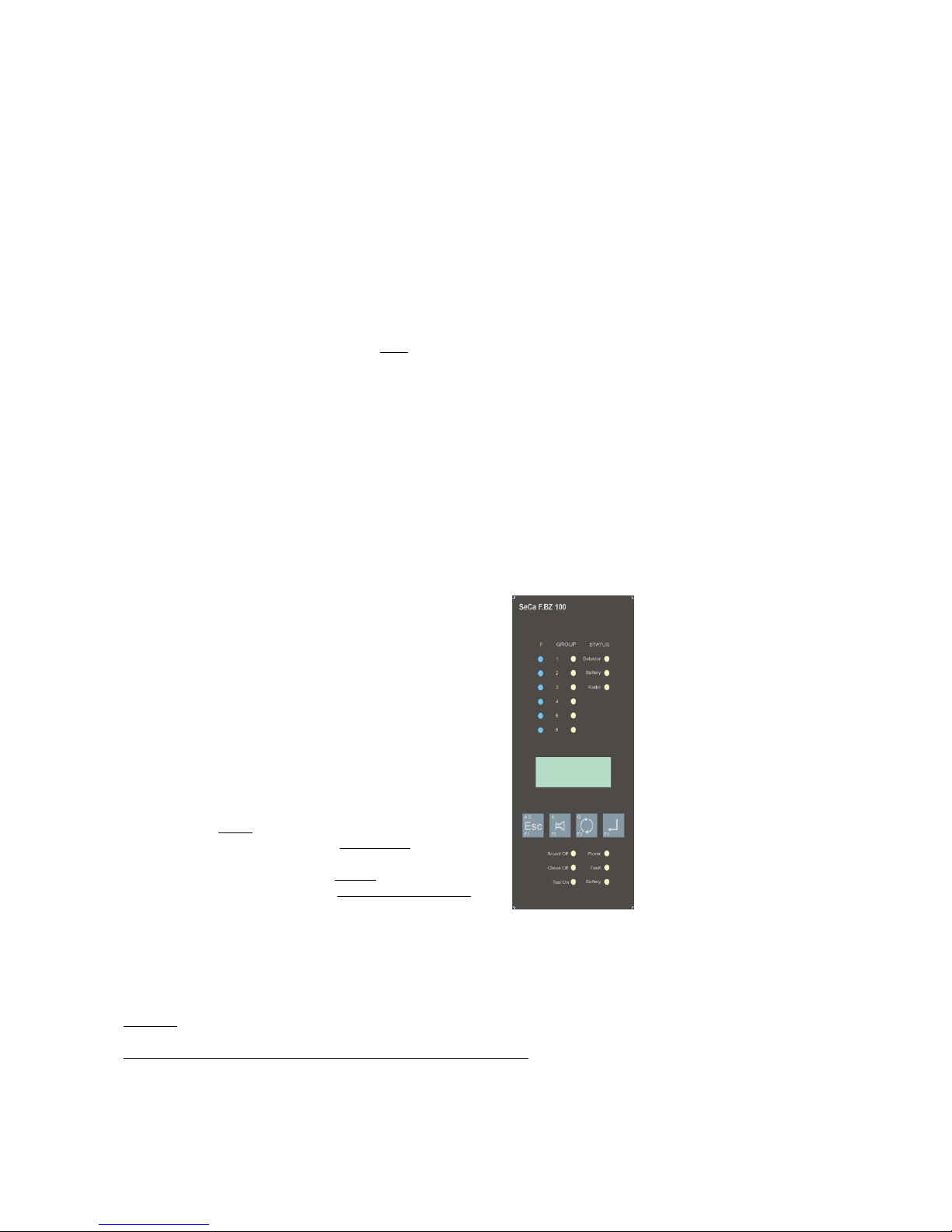
1.3 Operation and display elements
Programming keys P1 to P6 (double assignment)
Not assigned P 1 Alarm group 1
Not assigned P 2 Alarm group 2
Relays P 3 Alarm group 3
PIN code P 4 Alarm group 4
System parameters P 5 Alarm group 5
Radio telephone dialler P 6 Alarm group 6
To protect against unintentional activation, the programming keys are recessed. They are used for
system component registration and for configuration. With a short press on the key, the display
shows the next free address for registering a system
component, and the LED for the corresponding
group blinks. Pressing the key longer, until the LED
goes out, puts you into the configuration menu.
Both modes can be left by pressing the key again.
Function keys
Pressing F1 through F4 brings up the functions necessary for operation and service (see their corresponding sections in this manual).
Display and LEDs
Display: In status monitoring mode, the display shuts itself off after 10 minutes of inaction. Pressing the
F3 function key turns it on for about 10 seconds.
LED for system component status (upper part of display): When an event arrives, the corresponding
status LED lights up (Detector = malfunctions including power failure, Battery = battery replacement and
Radio = status report breakdown). Pressing function key F3 activates the display to show the event’s
system component address as well as that of the group displayed by the LED.
LED for status
sensors
Display
Function keys F1 to F4
(from right to left)
LED for control panel
status

SeCa CC100 PREMIUM system manual
Fundamentals for the authorized professional installer
© Copyright SeCa GmbH Page 5 of 32
LED for control panel status: (underneath the display): The system is working perfectly if only the Power
LED glows in status monitoring mode. If it blinks, the control panel isn’t getting any supply voltage and
will then work on emergency power (approx. 35 hours if there is no alarm).
The Fault LED blinks, if there is a control panel malfunction.
The Battery LED blinks if the emergency power batteries need to be replaced.
The Sound Off LED signals that all of the system’s acoustic signal generators are temporarily shut off.
The Check Off LED lights when the control panel is in unmonitored operation. In this mode, no malfunctions can be shown, but arriving alarms are signalled. This LED also lights when the control panel is connected to the PC; in this mode complete signalling is taken over by the PC.
The Test On LED lights up in maintenance mode (visual or visual plus acoustic alarm check – Configuration menu P5, System parameters 8 (Maintenance), setting 2 or 3. In this mode alarms are not forwarded and are signalled only visually (setting 2) or with a short acoustic tone (setting 3).
1.4 Installing the control panel
CC100P radio fire alarm control panel with integrated power adaptor
Please use VDE-tested connecting clamps for the power connection from the control panel to the supply
line. The separator and additional short circuit protection in the building installation must conform to
EN60950 / VDE 0805. The installation must be performed only by qualified electricians in observance of
applicable regulations.
1. First place the batteries for the emergency power supply into the battery compartment, making
sure to observe the correct polarity. Then connect the battery compartment to the battery clip.
Note: When the control panel is first connected to the power supply, the emergency power function
is initialized. To shut it off then, release the battery clip.
2. Before connecting the control panel to the supply line, cut the power to the supply line and secure
it against unintentional reactivation.
3. Connect the connector wires to the control panel and the 230V AC power supply to their respective
connecting clamps.
4. Use the included screws and anchors for installing the control panel. Install the lower screws first,
and then the upper ones.
5. Then turn the 230V AC power supply back on.
CC100P radio fire alarm control panel with plug-in power unit
The installation is done as described above, but there is no connection to the power supply line. Therefore the installation doesn’t need to be done by a professional electrician. Simply connect the plug-in
power unit to the connector socket after you have connected the emergency power batteries and have
installed the control panel.
1.5 Turning on the CC100P radio fire alarm control panel (initialization)
After power is connected, the device undergoes a self-test and then the green Power LED and the red
Check Off LED light up to indicate that there is no sensor status monitoring; the number 100 appears in
the display.
1.6 Configuration menu
P 1 and P 2 – not assigned

© Copyright SeCa GmbH Page 6 of 32
P 3 – Relays (events and assignment)
Three relays can be controlled through the adjacent
events. The display shows the first number of the
events, and the second shows the assigned relay.
Choose the event with the F4 and the relay with the
F3 key.
Fig.: Events for relays
(factory default 0 – no relay assigned)
Assignment of the DSUB-15 plug (relay connector cable)
Contact assignment
Note: The assignment of the cable colour to the contacts is included with the connector cable (item No.
4100080). Please note that the colour indicators — for
technical reasons — may differ. Important:
Use only the contacts indicated here, because otherwise
the control panel can be destroyed!
P 4 – PIN
Here an individual PIN can be entered; the factory default setting is 1111. The PIN prevents unauthorized access and for certain functions is requested several times (such as when deleting). To make the
configuration easier, an entered PIN works for 10 min. after the most recent activity (keystroke). Modifications are made with the function keys F3 (setting the number) and F4 (confirming the number and
changing to the next place). The PIN query can be deactivated though setting ―0000‖ (until the next general reset).
No.
Event
Display
1
Alarm Group 1
1_ _0
2
Alarm Group 2
2_ _0
3
Alarm Group 3
3_ _0
4
Alarm Group 4
4_ _0
5
Alarm Group 5
5_ _0
6
Alarm Group 6
6_ _0
7
Sensor malfunction
7_ _0
8
Control panel malfunction
8_ _0
9
not assigned
No display
10
not assigned
No display
11
Collective alarm
11_ _0
12
Collective failure
12_ _0
13
Operating mode: 0-static, 1pulsed
13_ _0
Relay A B
C
Relay 1
Contact 1
Contact 6
Contact 11
Relay 2
Contact 4
Contact 3
Contact 2
Relay 3
Contact 15
Contact 10
Contact 5
A
B
C

SeCa CC100 PREMIUM system manual
Fundamentals for the authorized professional installer
© Copyright SeCa GmbH Page 7 of 32
P 5 – System parameters
No
.
System parameter
Setting
De-
fault
1
Status reports
1-3
3
1 = 100
sec.
2
Sensitivity
1-6
2
1 = high
3
Fuzzy logic
0
0
factory
default
4
System key
1-50
1-50
5
Status reports
indirect
1-3
3
factory
default
6
System stability
<10000
00
7
Detector horns (global)
0-1 0 0 = off
8
Service
0-3 1 1 = on
9
Memory sound event
0-3
3
see below
10
Not assigned
11
Heterogeneous system
0
0
factory
default
12
Not assigned
SE
Reset maintenance interval
0-1
0
0-400 days
14
Automatic commissioning with topology build
A
Parameter 1: Status reports
Sets the maximum time period in which the status of all system components is checked (battery replacement, operation, radio connection). Setting 1 corresponds to 100 sec., setting 2 to 200 sec., etc.
(Tolerance until display: max. 15 sec., factory default setting: 300s according to EN54-25).
Attention: Watch out for the effects of Parameter 2. It can also change the time period!
Parameter 2: Sensitivity
Depends on the settings for building data and the desired notification time. The value set tells how many
status report failures (radio connection only) should trigger a signal to the CC100P control panel.
Parameter 3: Fuzzy logic
Special functions: These settings are made only at the factory.
Parameter 4: System key
Upon registration, each control panel, and the system components that belong to it, receive a number
that is unique to the system and is set here. Keep in mind that this number must be different for separate systems in the same range, because otherwise malfunctions will result.
Parameter 5: Status reports, indirect
These settings are made only at the factory.
Parameter 6: System stability
Display of absent status reports: 6_00 indicates a failure without outside signals, and 6‾ˉ00 a failure due
to them. Change the display using F1, reset by pressing F1 and F3 at the same time until the PIN is requested; then enter the PIN.
Parameter 7: Detector horn
All hazard detectors with an internal horn can be configured here, such that they can be turned on when
alarms are received from other detectors. When the horn is turned on (setting 1), all detectors of the
same group (alarm line) acoustically signal the alarm situation from other detectors. A MIDI 100
PREMIUM radio siren and flasher can additionally be configured so as to signal the alarm independently of
the group (see Configuration of the MIDI 100 PREMIUM in this system manual).
If the horn is shut off (setting 0 = factory default setting), only the detector that senses the alarm signals
it acoustically. Additionally, the MIDI 100 PREMIUM can signal this visually with a flasher (depending on the
settings). The control panel signals every event acoustically, regardless of this setting.
The system parameter settings are reserved for
the authorised professional installer. Unprofessional alterations to the factory default settings can lead to errors or to unintentional operations!
Please keep in mind that errors caused by improper settings are not covered by the legal
warranty.
In the P5 menu, use the function key F4 to
change between system parameters, and F3 to
set the value.
Fig.: Overview of system parameters
at factory default settings

© Copyright SeCa GmbH Page 8 of 32
Note: At commissioning, the setting will always be assigned (globally) to all detectors. An individual setting can be made only with the CC100 PREMIUM Assistant software. The MIDI 100 PREMIUM’s visual signal (flash) cannot be turned off. When there is an alarm, it flashes – depending on the setting – with or
independently from the affected group (alarm line).
Parameter 8: Service
Maintenance to the system is done according to applicable standards and regulations. It is recommended
that it be done at least once a year. Setting to setting 1 provides a reminder after 400 days through an
acoustic signal, which sounds approximately every 40 seconds if maintenance is due. The display shows
SE_1. The signal can be shut off temporarily by setting the value to 0. The maintenance interval (parameter SE) is reset after maintenance has been performed. For alarm testing the sensors without the
CC100 PREMIUM Assistant software, set value 2 (visual only) or 3 (visual and acoustic), the Test On LED
glows at this setting. If the alarms are acknowledged at the control panel, they are not forwarded.
Parameter 9: Memory sound event
The control panel can be notified approximately every 45 seconds when event reports, such as for malfunctions or alarms, have been acknowledged. This can be done by an acoustic signal or additionally by a
visual display. (See Point 1 ―Display and LEDs‖.) The following settings are possible:
Setting 0 - no signal
Setting 1 - acoustic and visual signal
Setting 2 - no acoustic signalling but only visual, radio malfunctions are automatically reset as soon as
they have ended.
Setting 3 - (factory default) acoustic and visual signal for expired alarms, sensor and battery malfunctions (no acoustic signal for radio malfunctions that are reset automatically).
Parameter 10: unassigned
Parameter 11: Heterogeneous system
These settings are made only at the factory.
Parameter 12: unassigned
Parameter SE: Maintenance interval
Display of SE_0 = within maintenance interval, and SE_1 = expired maintenance interval (400 days).
Pressing the F3 key shows the time elapsed since the previous service. Press F1 and F3 simultaneously to
reset the maintenance interval to its original value of 0. Entering the PIN one last time confirms the process.
Parameter 14: Automatic commissioning
Pressing F1 and F2 starts automatic commissioning, transferring the set parameters. Detectors with too
weak a signal during commissioning are automatically integrated through repeaters. If commissioning is
successful, the display shows ―P3‖. After unsuccessful commissioning, F0 to F15 are displayed. Confirm
this result by pressing F1. If commissioning is not successful, the error code (F0 to F16) is displayed, along
with the detector or repeater that caused the termination. An error code between F5 and F9 indicates an
error caused by a repeater (communication problems due to a weak signal). The other error codes indicate errors due to communication problems between the control panel and repeaters on one end, and the
other system components on the other.
Note: Be aware that commissioning is also terminated if the set minimum signal strengths are not
reached. To change them, you need the CC100 PREMIUM Assistant software.

SeCa CC100 PREMIUM system manual
Fundamentals for the authorized professional installer
© Copyright SeCa GmbH Page 9 of 32
P 6 – controlling the radio telephone dialler
No.
Event
Display
1
Alarm Group 1
1__0
2
Alarm Group 2
2__0
3
Alarm Group 3
3__0
4
Alarm Group 4
4__0
5
Alarm Group 5
5__0
6
Alarm Group 6
6__0
7
System component malfunction
7__0
8
Control panel malfunction
8__0
9
Collective alarm
9__0
10
Collective failure
10__0
Note: Event forwarding through the dialler to a corresponding call number must be set at the dialler (see
Configuring the radio telephone dialler).
1.7 Function keys
Pressing F1 through F4 brings up the special functions necessary for operation and service. Pressing two
keys at the same time, and the length of time they are pressed, brings up the functions detailed below:
Status and signal strength System components F3
Scrolling with the F3 key brings up the addresses of all registered system components. The glowing LED
shows each one’s group and — if available — the status for malfunctions. The addresses contain strokes
that indicate the status within the radio network (two dashes e.g. ―7=01‖ for sensors and signalling devices, three dashes ―9 01‖ for the 100 PREMIUM radio repeater) and the signal strength prefixed at
commissioning. If there is not enough signal strength for commissioning, a stroke is shown at that place
(- = 01). A commissioning value can be missing due to preset topology that has not been measured. For
that reason, this approach is not recommended.
Collective-call feature (all LED groups off) F2+F3
All detectors with activated horns (see Parameter 7) are called. This type of calling is suitable for checking mute switching of system components, because only system components with activated horns respond. When the control panel is in normal operating mode (no address on the display and all LED groups
off), press F2+F3 until the display shows FF and a revolving zero as a symbol of the calling process. In
monitored operation, the call duration is a maximum of 25 sec., and in unmonitored operation 120 sec.
(regardless of the chosen settings or topology) for individual detectors. With the radio siren/flasher of the
MIDI 100 PREMIUM, the flasher activates if the siren is muted. Pressing F2+F3 again ends the call. If the
call does not end, after about three minutes the horns turn themselves off autonomously (time out), and
the flashers will change their interval from 2 to 8 seconds. The flasher can be stopped only by a new call
with the OFF signal.
Attention: Pressing the keys alternately turns the collective-call feature either on or off. The display
shows a right-rotating zero (OFF) or a left-rotating zero (ON). If a call is ended improperly, the next call
can send an OFF or ON signal. In that case, repeat the process!
Single call F4
Set the desired address of the detector that is to call by scrolling in the display using the F3 key, then
immediately press F4 until the display shows the detector address at the left, and at the right a rotating
zero to indicate the calling process. Maximum call duration is 25 sec. The detector responds intermittently with a short (activated horn) or long uninterrupted melody (deactivated horn). This function is
suitable for testing the horn settings and for identifying individual detectors.
List of indirect system components (repeater address in display) F2+F3
To receive the assignment of the system components to their respective repeater, use F3 to scroll to the
desired repeater address (e.g., 9 01), and then immediately press F2 and F3 briefly. You can use F3 to
call up all assigned addresses. To get the normal display back, use F1 to delete these addresses one after
the other.
First press F3 to determine the dialler model
(choices: 0 for no dialler, 2 for medium or 4 for
large). Then order the events to the dialler’s input
lines as follows:
In the display the first number shows the event and
the second shows the assigned input line of the
dialler. Choose the event with the F4 key and the
input line with the F3 key.
Fig.: Events for dialler without an assigned line
(factory default setting).

© Copyright SeCa GmbH Page 10 of 32
Mute switching during an alarm F2
If an alarm is signalled acoustically, you can use F2 to shut it off temporarily for about 3 minutes, in o rder to determine the cause. All actions are reset within 20 sec. (max. 36 sec.), the display remains and
the Sound Off LED blinks. After that time has expired, the actions are enabled again within 30 sec.
Note: If during that time an alarm from another sensor is received, mute switching is cancelled.
Confirm an event F1
Malfunctions or alarms can be confirmed through F1 (version 60 and above). Their associated signals to
the control panel are reset immediately, and those to the other system components are reset after about
20 sec. (max. 36 sec.).
Note: A dialler-forwarded alarm that has already been triggered at the time of confirmation can no
longer be reset.
Deleting individual addresses (approx. 10 sec.) F1
Set the desired address of the detector that is to delete by scrolling in the display using the F3 key, then
immediately press F1 until the LED group and address stop blinking. Entering the PIN one last time confirms the process.
General reset (approx. 10 sec.) F1+F3
Press F1 and F3 until all group LEDs stop blinking. Entering the PIN one last time confirms the process. If
all settings are reset to factory default, only the system key and the data in event memory remain.
Other functions
In addition to those mentioned above, the following functions can be performed only with the CC100
PREMIUM Assistant software:
Configuring dual detector dependency (four pairs)
Determining minimum signal strengths for automatic topology build-up
Individual detector horn settings
Restart function for subsequent commissioning of individual system components.
Measuring battery voltage and the current signal strength of all or individual system compo-
nents
Visualizing and printing various logs and topologies
Signal strength charts (values for the system components to all repeaters and to the control
panel)
Integrated analyser function
1.8 System registration
Registering the system components
1. Before you do the registrations, go into configuration menu P5 and set the system parameter 8 to
the value of 3 (visual and acoustic alarm testing). This prevents an unintentionally sent test alarm
from triggering a collective alarm.
2. Register the system components under their respective groups, therefore briefly press the corre-
sponding programming key, and the next free address will be shown.
3. Then briefly press twice the programming key of the radio module on the participant to be regis-
tered.
4. Successful registration will be indicated at the control panel by a long glow of the corresponding
group’s LED and by the appearance of the received radio signal in the display.
5. After about 10 sec., the group’s LED shut off, and the control panel is ready to register more sys-
tem components.
Registration errors:
Failed registration can have various causes. The following are common mistakes that you should rule out:
The registration mode was not activated at the control panel.
The radio module has already been logged on and is addressed. Do a general reset of the radio
module and log in again. When in doubt, you can use the CC100 PREMIUM Assistant software to
read out the data (see Chapter 11, Radio module status information).
The login has occurred immediately after the voltage was applied. Previously addressed radio
modules are in receiver mode for the first 30 seconds after the voltage is applied. Meanwhile, all
other functions are locked, so a login or test alarm is not possible. Wait 30 sec. and then repeat
the process.
The system component has no power (battery not connected or drained, etc.).
 Loading...