

Page 1

RTX 2251 – RTX 2252
Battery LOW
3) CODE 2 CH1 Battery OK Battery LOW
4) CODE 3 CH1 Battery OK Battery LOW
Battery LOW
6) CODE 2 CH2 Battery OK Battery LOW
7) CODE 3 CH2 Battery OK Battery LOW
GB
868 MHz radio system to be used as safety device in the automation of sliding gates and rolling gates (EN 12978). It consists
of one transceiver device (Base) RTX 2251 to be connected to
a motor control unit, and of one or more battery operating
CN1 T
ERMINAL BOARD CONNECTIONS
1: 230V~ Line input (Phase).
2: 230V~ Line input (Neutral).
transceiver devices RTX 2252 (Sensor), for the connection of
8.2 kohm resistive and mechanical safety edges,
found in the gate's mobile part
. System corresponding to
Category 2 of EN13849-1.
F
UNCTIONING FREQUENCY SELECTION
The system allows the selection of four 868 MHz band frequencies.
Set the same frequency on the RTX2251 (Base) and on the
memorised RTX 2252 (Sensor) devices.
Use Dip Switch SW1 on both the RTX 2251 and RTX 2252
devices for the selection.
SW1 SW1 SW1 SW1
normally
CN3 T
ERMINAL BOARD CONNECTIONS
1: 24V AC-DC Power supply input.
2: 0V Power supply input.
3: 12V AC-DC Power supply input.
4: CH1 Control output.
5: CH1 Control output.
6: CH2 Control output.
7: CH2 Control output.
8: 12-24V AC-DC Test Input.
9: 0V Test Input.
10: Aerial earth input.
11: Aerial hot pole input.
F
UNCTIONING DESCRIPTION
The RTX 2251 (Base) device controls one or more RTX 2252
(Sensor) devices through radio-frequency, for connection of
sensitive edges.
The RTX 2251 (Base) allows the display of 2 menus:
F
REQUENCY A FREQUENCY B FREQUENCY C FREQUENCY D
RTX 2251 (B
ASE
)
- Mod. RTX 2251 : 12-24 VAC-DC
- Mod. RTX 2251 230V : 230 VAC
By means of MONITOR MENU and acoustic signals (Buzzer)
the Device highlights the following informations:
T
EST ANOMALY SIGNAL
LED switch-on + Buzzer.
Highlights an anomaly in executing the test by the control unit
- MONITOR MENU
- PROGRAMMATION MENU
:
(see "DEVICE TEST" paragraph).
A
LARM SIGNAL:
LED Switch-on + Buzzer.
Informs which of the RTX 2252 memorised devices is in alarm.
A short Beep corresponds to every LED of reference switch-on.
---------------------- MONITOR MENU -----------------
LED Reference LED Off LED On
1) TEST Test = OK Test = INC.
2) CODE 1 CH1 No Alarm CODE 1 CH1 Alarm
3) CODE 2 CH1 No Alarm CODE 2 CH1 Alarm
4) CODE 3 CH1 No Alarm CODE 3 CH1 Alarm
5) CODE 1 CH2 No Alarm CODE 1 CH2 Alarm
6) CODE 2 CH2 No Alarm CODE 2 CH2 Alarm
7) CODE 3 CH2 No Alarm CODE 3 CH2 Alarm
D
ISCHARGED BATTERY SIGNAL:
LED Switch-on (quick Flashes) + Buzzer.
Informs which of the memorised RTX 2252 devices has discharged batteries. Every minute two quick Buzzer Beeps are
transmitted and the LED of reference switches-on.
---------------------- MONITOR MENU -----------------
LED Reference LED Off Flashing LED
T
ECHNICAL DATA
- Power supply: See model
1) TEST NOT USED NOT USED
2) CODE 1 CH1 Battery OK
- Max. consumption: 4.5 W
- Work frequency: 868 MHz FSK Band
5) CODE 1 CH2 Battery OK
- No. 2 control relay for CH1 and CH2: 30VDC 1A
- Memorisable RTX 2252 sensors: Max 3 for each channel
- Range in free space: 10÷20 m max.
- Response time: 200 ms
- Working temperature: -10°C ÷ 55°C
- Dimensions: 110x121x47mm
- Container: ABS (UL94V-0)
- Protection rating: IP54
1
As for PROGRAMMATION MENU see paragraph “Programming Keys and Indicator Leds”.
8K2/C
ONTACT FUNCTIONING MODE SELECTION
The RTX 2251 (Base) device selects the CH1 and CH2 relay
control outputs.
Page 2

Selection is through Jumper 1 – 2:
ON
J1 pos. 1-2 = NC CH1 relay output (default).
J1 pos. 2-3 = 8K2 CH1 relay output.
J2 pos. 1-2 = NC CH2 relay output (default).
J2 pos. 2-3 = 8K2 CH2 relay output.
DEVICE TEST
The RTX 2251 (Base) device has a "Test" input to be used
when the control unit it ‘s coupled with is equipped with Safety
Devices test function. Test is performed as follows: the control
unit must switch the signal in "Test" input from high logic level
(12-24 Vac-dc during normal functioning) to low logic level: the
RTX 2251 device must respond varying the state of the two
CH1 and CH2 channels outputs to pass the test.
C
ONTROL OF THE SELECTED FREQUENCY
Before programming the RTX 2252 (Sensors) codes associated to the RTX 2251 (Base) it’s necessary to select one of the
four frequency channels available (see paragraph “Functioning
Frequency selection”) and it’s advisable to verify that the channel selected is free; to do that proceed ad follow: with SET button go to PROGRAMMATION MENU; the Base makes a scanning of the channel selected and if it’s busy the Base will signalize this with an alternately flashing of LED MONITOR and
LED MENU PROGR.. In this case choose an other frequency (
on Base and on Sensor). If the channel selected is free, makes
the programming of the Sensor as indicated in the next paragraph.
P
ROGRAMMING KEYS AND INDICATOR
LEDS
SEL Key: selects the type of function to memorise, the choice
is indicated by the flashing of the LED. Repeatedly press the
key to position oneself on the desired function. After 15 seconds of activation displayed by the flashing LED, the device
returns to original state.
SET Key:
- selects between Monitor Menu and Programming Menu: the
Monitor Menu is automatically selected after 1 minute of SEL
and SET keys inactivity.
- programs the function chosen with the SEL key.
Indicator LED
LED on: option memorised.
LED off: option not memorised.
Flashing LED: option selected.
---------------------- PROGRAMMING MENU -----------------
LED Reference LED Off LED On
1) TEST Test Saf. Dev. = OFF Test Saf. Dev. =
2) CODE 1 CH1 No Pgm. Code Code 1 on CH1 Pgm.
3) CODE 2 CH1 No Pgm. Code Code 2 on CH1 Pgm.
4) CODE 3 CH1 No Pgm. Code Code 3 on CH1 Pgm.
5) CODE 1 CH2 No Pgm. Code Code 1 on CH2 Pgm.
6) CODE 2 CH2 No Pgm. Code Code 2 on CH2 Pgm.
7) CODE 3 CH2 No Pgm. Code Code 3 on CH2 Pgm.
CH1 of RTX 2251 (Base) Transceiver Device, is programmed
as follows: press SEL and CODE 1 CH 1 LED starts flashing;
the Base broadcasts to all Sensors, searching for one to be
memorised: press SET key of the Sensor you want to program
to send the memorisation confirmation code ( TX LED makes 5
quick flashes); CODE 1 CH LED remains on and programming
is complete. The Base device exits programming if no confirmation code is received within 15 seconds.
Deletion The memorised code is deleted as follows: press
SEL and CODE 1 CH1 LED starts flashing; press SET, CODE
1 CH1 LED switches off and the procedure is complete.
3) CODE 2 CH1 (Programming of n.2 RTX 2252 Sensor
transceiver device coupled with CH1)
Proceed as described in point “2) CODE 1 CH1” to program the
transmission code of n. 2 RTX 2252 (Sensor) Transceiver Device coupled with CH1 of RTX 2251 (Base) Transceiver Device.
4) CODE 3 CH1 (Programming of n.3 RTX 2252 Sensor
transceiver device coupled with CH1)
Proceed as described in point “2) CODE 1 CH1” to program the
transmission code of n.3 RTX 2252 (Sensor) Transceiver Device coupled with CH1 of RTX 2251 (Base) Transceiver Device
5) CODE 1 CH2 (Programming of n.1 RTX 2252 Sensor
transceiver device coupled with CH2)
Proceed as described in point “2) CODE 1 CH1” to program the
transmission code of n.1 RTX 2252 (Sensor) Transceiver Device coupled with CH2 of RTX 2251 (Base) Transceiver Device.
6) CODE 2 CH2 (Programming of n.2 RTX 2252 Sensor
transceiver device coupled with CH2)
Proceed as described in point “2) CODE 1 CH1” to program the
transmission code of n. 2 RTX 2252 (Sensor) Transceiver Device coupled with CH2 of RTX 2251 (Base) Transceiver Device.
7) CODE 3 CH2 (Programming of n.3 RTX 2252 Sensor
transceiver device coupled with CH2)
Proceed as described in point “2) CODE 1 CH1” to program the
transmission code of n.3 RTX 2252 (Sensor) Transceiver Device coupled with CH2 of RTX 2251 (Base) Transceiver Device.
R
ESET
Keep the SEL and SET keys simultaneously pressed for more
than 2 seconds so that all indicator LEDs briefly switch on at
the same time accompanied by three quick Buzzer Beeps, if
the device must be reset to company configuration.
RTX 2252 (S
ENSOR
)
1) TEST (RTX 2251 (Base) device functional test).
Functional test of RTX 2251 (Base) device, if combined with
motor control unit equipped with Safety Devices test (see
"RTX2251-DEVICE TEST" paragraph).
Test enabling on the Device is carried out as follows: press
SEL and TEST LED will start to flash. Press SET, the TEST
LED remains on and programming is complete. Repeat the
procedure to restore previous configuration without active
TEST.
2) CODE 1 CH1 (Programming of n.1 RTX 2252 Sensor
transceiver device coupled with CH1)
The n.1 RTX 2252 (Sensor) Transceiver Device coupled with
1
T
ECHNICAL DATA
- Battery power supply: 2 x 1.5Vdc Alkaline (AA)
- Work frequency: 868 MHz FSK Band
- Range in free space: 10÷ 20 m max.
- Working temperature: -10÷55°C
- Dimensions: 120x80x50 mm.
- Container: ABS UL94V-0 (IP56)
Page 3
CN1 T
ERMINAL BOARD CONNECTIONS
CN1:
1 : (NC) or 8K2 Safety device input
2 : (NC) or 8K2 Safety device input.
3 : Inhibitor Input (NC).
4 : Inhibitor Input (NC).
F
UNCTIONING DESCRIPTION
The RTX 2252 (Sensor) device enables connection of NC
(normally closed contact) classic type or 8K2 resistive type
sensitive edges, normally found in the gate's mobile part.
Only works coupled with the RTX 2251 control (Base). The
device is battery powered to exclude every type of cable connection.
Once memorised (see "RTX 2251 - Programming Keys and
Indicator LED" paragraph) it can send the following information
to the RTX 2251 (Base) device:
- Survival signal:
used to periodically check the correct radio connection be-
tween the devices.
- Alarm signal:
used to inform the Base device that the safety device is activated.
- Discharged battery signal:
used to inform the Base of the battery state.
ATTENTION! If one RTX 2252 (Sensor) is no more used, re-
move the batteries to avoid the Device goes on transmitting.
NC
OR
8K2 F
UNCTIONING MODE SELECTION
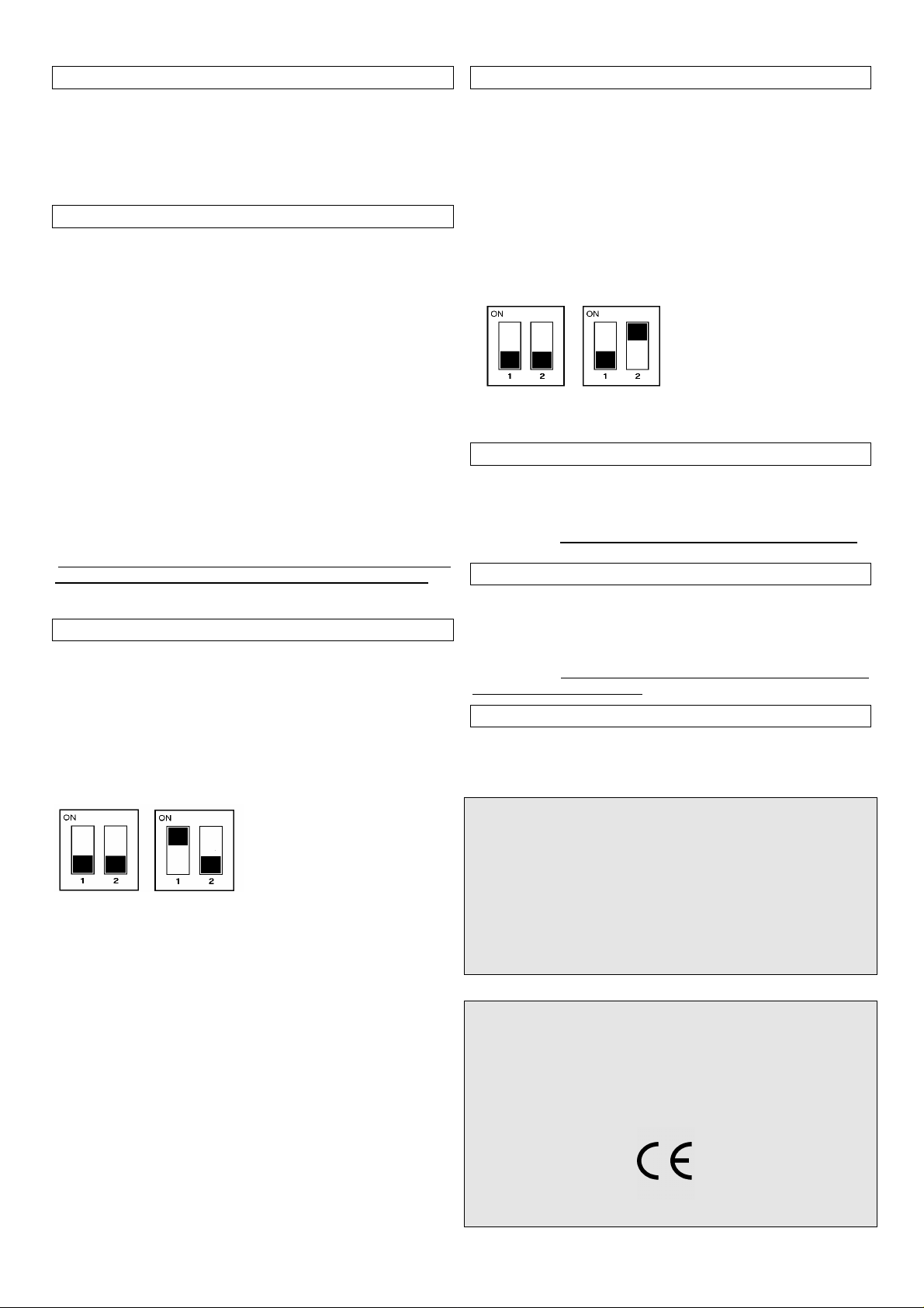
RTX 2252 device enables connection of NC (normally closed
contact) classic type or 8K2 resistive type sensitive edges. Use
n. 1 Dip Switch SW2 to select:
DIP 1 = OFF NC input (default).
DIP 1 = ON 8K2 input .
SW2 SW2
NC 8K2
T
RANSMISSION MODE SELECTION
The RTX 2252(Sensor) allows to select two different transmission modes, “normal” or “ low power”. The difference between
the two modes is the transmission power of the Sensor. In “low
power” mode the power is lower: the battery duration increase,
but the range is smaller; consider that when you make an installation.
DIP 2 = OFF “normal”(default).
DIP 2 = ON “low power” .
SW2 SW2
LP=OFF LP=ON
I
NHIBITOR INPUT FUNCTIONING MODE
RTX 2252 (Sensor) device enables connection of an (NC) contact for the temporary inhibiting of the sensitive edge it is connected to.
ATTENTION! If not used the inhibitor must always be jumped.
D
ISCHARGED BATTERY SIGNAL
The RTX 2252 (Sensor) device signals the discharged battery
state through quick flashing of the TX LED. The same information is also sent to RTX 2251 (Base) device, that signals the
event with visual and acoustic warnings.
ATTENTION! We recommend immediately replacing the device
batteries if TX LED flashes.
RESET
To reset the factory configuration, press and hold the SET key
for more than 2 seconds until the TX LED flashes 3 times.
ATTENTION
-For excellent functioning, annually replace the 1.5V (AA) alkaline batteries.
-To change batteries open by the means of a screwdriver the
case of the Sensor.
-Dispose of the used batteries in appropriate containers.
the product:
RTX 2251-RTX 2252 Radio system
is conform with Directives
2004/108/EC
, LVD 2006/95/EC specifications.
R&TTE 99/5/EC, EMC
1
Page 4

RTX 2252 radio system is designed to help
Important for the installer
• The RTX 2251the installer to automate gates in compliance with Machinery Directive 2006/42/EC.
• The installer must check that all requirements in the com
plete automation prescribed in EN 12453 and EN 12445 are
satisfied.
• IMPORTANT: In order to obtain the required safety level,
(EN 12978) the device must be used in conjunction with
control units equipped with the function to test the security
devices and activate the “Test” function on the RTX2251
(Base) device.
• The control unit has no sectioning device for the 230 Vac
electrical supply, therefore the installer must provide a sectioning device. An omnipolar switch with overvoltage category III . This must be positioned so that is protected
against accidental closure as set for in point 5.2.9 of EN
12453.
• For a higher safety level we recommend to use control units
with the safety devices test function and activate the “Test”
function on the RTX 2251 (Base) device.
• Carefully choose the place of installation to obtain excellent
radio system functioning. Capacity is not only related to the
device technical data, but also varies depending on the
site's radio-electric conditions.
• The RTX 2251 device is equipped with rigid wire section
antenna. Connect an RG58 50 OHM coaxial cable tuned
antenna if wanting to increase sensitivity. Place the antenna
externally in clearly visible points and away from metal
structures.
• It is not possible to install two RTX 2251 (Base) Transceiver
Devices that are not at least 5 m away from each other.
Warning
All operations that require the opening of the casing (cables
connection, programming, etc.) must be carried out by expert
personnel during installation. For any further operation which
requires the casing to be re-opened (re-programming, repair or
installation amendments) contact the after-sales assistance.
IMPORTANT FOR THE USER
- The device must never be used by children or persons with
reduced physical-psychological abilities, unless supervised or
trained on the functioning and the use modalities.
- Do not allow children to play with the device and keep the
radiocontrols away from their reach.
- Ensure there is no-one immediately near-by until the door is
not fully open or closed.
- ATTENTION: keep this instruction manual and respect the
important safety prescriptions contained herein. The non compliance with the prescriptions may cause damages and serious
accidents.
- Frequently examine the plant to detect any signs of damaging. Do not use the device if a repair intervention is necessary.
Rev. 1.3 del 18/10/12
Usage restrictions:The RTX 2251 – RTX 2252 radio system
may not be used on equipment excluded from being subject to
EN12978, such as:
- protective equipment to be installed on doors meant for a use
other than those on vehicle or pedestrian access, covered by
the regulation and whose main use is to give secure access to
industrial, commercial, public or residential locations.
- devices used only for the normal control and stop, including
emergency stop, of motorized doors.
- safety equipment or safety devices for use on machines other
than doors.
ATTENTION: Any changes to the product or the configuration
of the equipment may not be performed without first consulting
the manufacturer or its authorized representative.
The safety device installer must supply the final user with the
following:
- the safety devices must be made known to all appropriate
persons.
- the areas that access the devices must be kept free of obstacles;
- the requirements for cleanliness in order to prevent any dangerous accumulation of material;
- possible details for a restart procedure to be performed after
an emergency or accidental stop caused by the control system.
Changes to the design or configuration of the equipment without consulting the manufacturer or its authorized representative
could create dangerous situations.
1
 Loading...