

Page 1
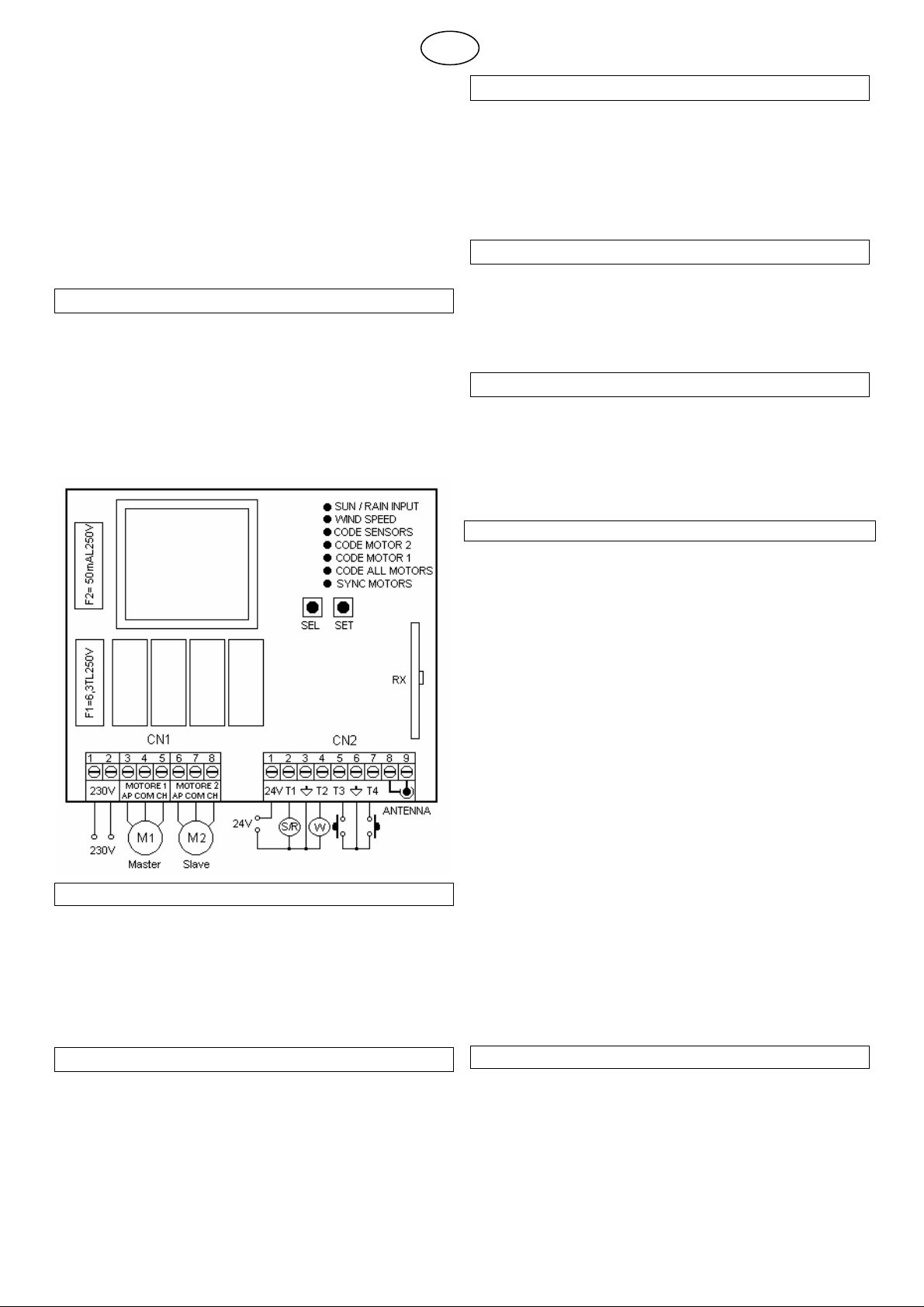
LRX 2247 Electronic Control Unit
GB
Electronic control unit, for simultaneous automation of 2 motors
for rolling window shutters and sun blinds installed both on the
same transmission roller and individually. The control unit can
be activated using push button panel and radio control, for individual and centralised control, it includes inputs for a wired
Wind, Sun or Rain Sensor. It is also capable of communicating
with the Wind, Sun and Rain Sensors.
- Mod. LG 2247: Without Radio Receiver
- Mod. LRS 2247: 433,92 MHz
- Mod. LRS2247 SET: “Narrow Band” 433.92 MHz
- Mod. LRH 2247: “Narrow Band” 868.3 MHz
T
ECHNICAL DATA
- Power supply: 230V~ 50/60Hz 1250W max.
- Motor output: 2 x 230V~ 600W Max.
- Working temperature: -10÷55°C
- Radio receiver: see model
- Compatible radio-controls: 12-18 Bit - Rolling Code
- Amount of Radio-controls that can be memorised: 7 Max.
- Amount of Wireless Sensors that can be memorised: 1 Max.
- Packaging dimensions: 110 x 121 x 47 mm.
- Container: ABS UL94V-0 (IP54)
S
YNCHRONISATION OF 2 STANDARD MOTORS
The control unit allows synchronisation of 2 Standard Motors
that are the same and installed on the same transmission
roller. Motor 1 is defined as Master (Motor that the Mechanical
Ascent and Descent End runs must be adjusted to ) and Motor
2 is defined as Slave (Motor on which the end runs do not have
to be adjusted). This way once the Ascent or Descent end run
set on Motor 1 is reached, the control unit also immediately
stops Motor 2.
A
UTOMATIC MOTOR TIMER
The control unit is supplied from the manufacturer with the
Automatic Motor Timer function; this way the control unit cuts
power to the motors 1 sec. after the internal motor end run has
been reached or when the motors stop due to overheating.
Moreover, the power to the motors is cut in any case if it exceeds 4 minutes of operation.
I
NITIAL FUNCTIONING CONDITION
Factory settings for the control unit are to control 2 Standard
Motors Synchronised with each other and with the possibility of
connecting a wired Sun or Rain Sensor input T1 (if selected), a
wired Rain Sensor input T2 and two distinct control buttons T3
( Ascent ), T4 ( Descent ). It must also be possible to command
the control unit using one or more radio controls if properly
trained.
C
ONNECTIONS OF THE
1: 230V~ Line input (Phase).
2: 230V~ Line input (Neutral).
3: Ascent Motor 1 ( Master ) Output.
4: Common Motor 1 ( Master ) Output.
5: Descent Motor 1 ( Master ) Output.
6: Ascent Motor 2 ( Slave ) Output.
7: Common Motor 2 ( Slave ) Output.
8: Descent Motor 2 ( Slave ) Output.
C
ONNECTIONS OF THE
1: Sun Sensor power supply output 24Vac.
2: Sun or Rain T1 Sensor Input.
3: Common input GND Signal.
4: T2 Anemometer input (Rain Sensor).
5: Ascent button T3 input (NA).
6: Common input GND Signal.
7: Descent button T4 input (NA).
8: Aerial earth input.
9: Aerial hot pole input.
CN1 T
CN2 T
ERMINAL BOARD
ERMINAL BOARD
OPERATING FEATURES:
Operation of the T1 input (Sun or Rain Sensor):
By connected a Sun Sensor to the low-voltage T1 input, the
electrical control unit will control blind Descent after 10 minutes
where luminosity exceeds the threshold selected in the Sun
Sensor, displayed when the SUN LED turns on. Subsequently,
it will control Ascent of the blind after 10 minutes of luminosity
under the selected threshold.
By selecting Led SUN/RAIN INPUT ON in the main menu, it is
possible to connect a Rain Sensor instead of a Sun Sensor.
The electronic control unit controls the descent of the blind as
soon as the sensitive part of the Rain Sensor is wet from rain.
T2 Anemometer input operation (Wind Sensor):
By connecting a Wind Sensor to the low-voltage T2 input, the
electrical control unit will control the ascent of the blind every
time wind exceeds the intervention threshold selected in the
Led WIND SPEED main menu.
T3 – T4 input operation
(Ascent – Descent control buttons):
The following type of operation is obtained by connecting the
local command buttons (normally open) for movement activation to the low voltage inputs T3 – T4:
T3 controls upward movement until the motor running time has
elapsed and T4 controls downward movement. If a command
is sent in the same direction before the motor running time has
elapsed, the control unit will stop movement; if a command is
sent in the opposite direction before the motor running time
has elapsed, the control unit will invert the direction of the motor.
F
UNCTIONING WITH DIFFERENT RADIO-CONTROLS MODELS
IT is possible to program different radio control models: by
memorising a code (1 key) a Step-by-Step cyclical functioning
is obtained; (Ascent -Stop-Descent) by memorising two different codes (2 keys) distinct controls are obtained. The first for
Ascent and the second for Descent, by memorising a BeFree
series radio control (3 keys) distinct controls are obtained, the
first for Ascending, the second for Stopping and the third for
Descending.
1 Rev. 1.5 26/04/2012
Page 2
Operation with 1 button radio control:
6) WIND SPEED Wind Safety 25 Km/h Pgm. Wind Safety
Using the radio-control with only one key, the following functioning is obtained: the first impulse controls Ascent until it
reaches the end run internal to the motor or until motor time
expires. The second impulse controls the Descent of the fastening; if an impulse occurs before until it reached the internal
motor end run or before motor time expires, the control unit
stops the fastening; a further impulse carries out the motion restart in the opposite direction.
Operation with 2 button radio control:
Using the radio control with two buttons, the following operation
is obtained: the first key (“Up” associated with the ascent direction) controls Ascent until it reaches the internal motor end run
or motor time expires, the second key ( “Down” associated with
the Descent direction ) controls fastening Descent. If during
Ascent the Up control is given again, the control unit continues
to Ascent whereas, while if the Down control is given, the control unit stops movement.
The same procedure is valid during Descent phase.
Operation with 3 button radio control (BeFree x1):
Using the BeFree x1 radio control, the following operation is
obtained: the ( Up ) key controls ascent until it reaches the internal motor end run or motor time expires, the ( Stop ) key
controls stopping and the ( Down ) key controls fastening descent. If during ascent or descent a (Stop) control is given, the
control unit stops the fastening. If during ascent or descent a
control is given of the opposite current direction, the control
unit reverses gear.
Operation with 3 keys radio control (BeFree x3 - X6):
Using the BeFree x3 – x6 radio control, the operation previously described for the BeFree x1 version is obtained. Using
the two side keys ( – ) and ( + ) of the radio control it is also
possible to select controls ( Up - Stop - Down ) for 3 different
utilities (BeFree x3) or for 6 different utilities (BeFree x6).
Enabling of Sun Sensor with 3 keys radio-control (BeFree
x3 - X6):
The enabling of the Sun Sensor can be carried out as follows:
continuously press for 5 seconds the ( + ) key of a previously
memorised radio-control; the control unit will move Up/Down
for 1 second to confirm the occurred enabling of the Sole Sensor. It is possible to repeat the operation to disable the Sole
Sensor using the same procedure, but by continuously pressing the (-) key for 5 seconds.
V
ERIFICATION OF THE ROTATION DIRECTION
Attention, after connecting the control unit, Motors, especially if
using with synchronised operation, make sure that the two motors have the same rotation direction and that, when given an
Ascent command from button or radio control, the control unit
actually completes the Ascent, and the Motors carry out Descent if the Descent command is given. If not, restore wire
connections of the motor correctly.
G
ROUP OR MAIN CENTRALISATION
Centralisation by way of cable using buttons
Centralisation of two or more control units by cable allows simultaneous Ascent or Descent movement of connected fastenings. Centralisation is carried out by connecting the three input
wires T3 ( Up ), T4 ( Down ) and the common reference “GND
Signal” in parallel.
Centralisation by was of radio using radio control
Centralisation of two or more control units by radio allows simultaneous Ascent or Descent movement of fastenings.
Centralisation is carried out by inserting equal radio-control
codes (keys) to all control units or by group, at a distance not
higher than 20 metres from the control point, in order to obtain
the total or partial movement of multiple automations. For optimal radio centralisation functioning, it is very important to
choose the place of installation carefully. The field of action is
not only related to technical characteristics of the device, but
also varies based on radio-electric conditions of the area.
O
PERATION OF THE WIRELESS ANEMOMETER
The electrical control unit will control fastening ascent every
time wind exceeds the intervention threshold selected by the
Wireless Wind sensor.
O
PERATION OF THE WIRELESS SUN SENSOR
The electrical control unit will control blind Descent after 10
minutes where luminosity exceeds the threshold selected in
the Wireless Sun Sensor. Subsequently, it will control fastening Ascent after 10 minutes of luminosity under the selected
threshold.
O
PERATION OF THE WIRELESS RAIN SENSOR
The electronic control unit controls fastening descent as soon
as the sensitive part of the rain sensor is wet from rain.
P
ROGRAMMING KEYS AND INDICATOR
SEL Key: selects the type of function to memorise, the choice
is indicated by the flashing of the LED. By repeatedly pressing
the key, it is possible to position oneself on the desired function. The selection remains active for 15 seconds, displayed by
the flashing LED, after which the control unit returns to the
original status.
SET Key: carries out the programming of the function chosen
with the SEL key.
Indicator LED
LED on: option memorised.
LED off: option not memorised.
LED flashing: option selected.
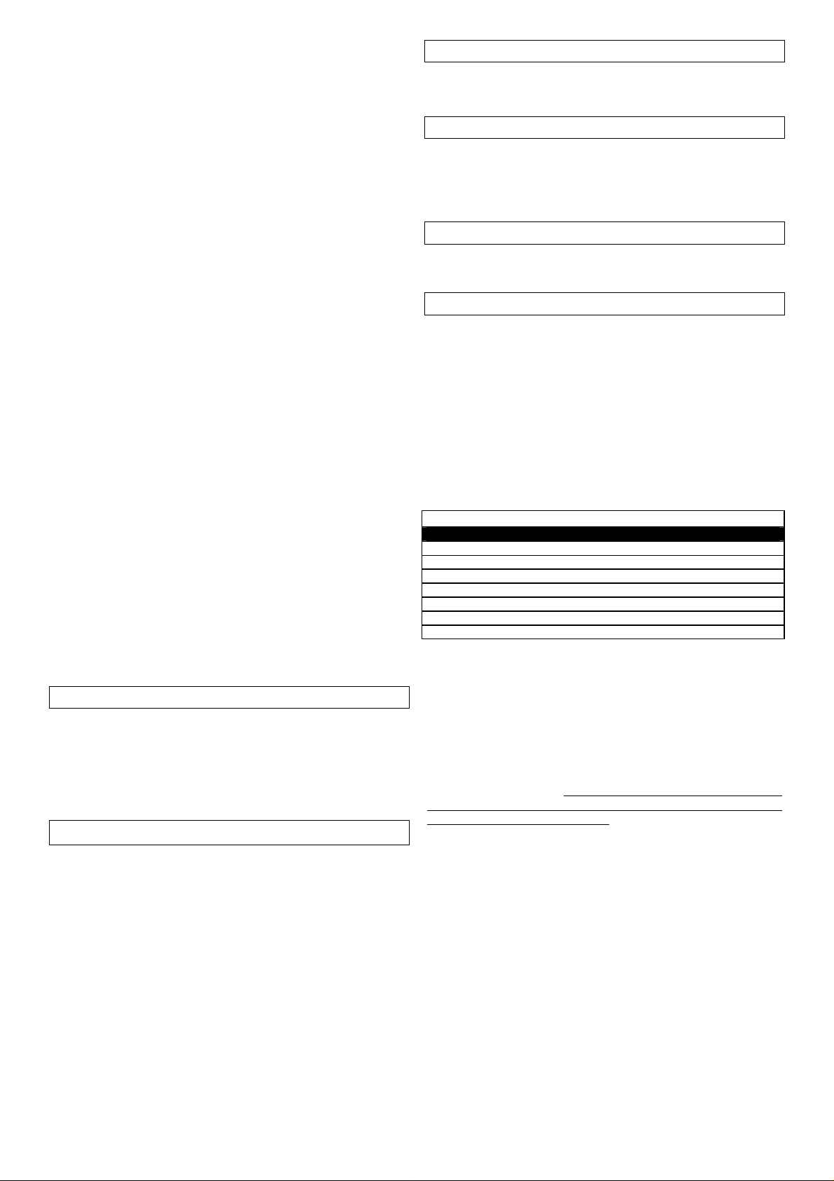
---------------------- MAIN MENU -----------------
LED Reference LED Off LED On
1) SYNC MOTORS Independent Motors Synchronised Motors
2) CODE ALL MOT. No code Code TX M1+M2 Pgm.
3) CODE MOT. 1 No code Code TX M1 Pgm.
4) CODE MOT. 2 No code Code TX M2 Pgm.
5) CODE SENS. No code Pgm Sensors Code.
7)SUN/RAIN INPUT Sun Sensor Rain Sensor
1) SYNC MOTORS ( Motor Synchronisation )
The control unit is supplied by the manufacturer with operation
of Motor 1 and Motor 2 Synchronised with each other, if operation is required as Motor 1 and Motor 2 independent, proceed
as follows: position the SEL key on the flashing of SYNC
MOTORS LED then press the SET key, the SYNC MOTORS
LED will simultaneously switch off permanently and the programming is completed. Repeat the procedure to restore the
previous configuration. Be careful whenever you change the
operation of this mode, the control unit cancels (Reset) the
configurations previously stored.
2) CODE ALL MOT. ( Programming of the radio control for
controlling both MOT.1 and MOT.2 Motors)
Programming of 1 or 2 button radio commands.
The transmission code is programmed in the following manner:
press the SEL key, CODE ALL MOT. LED will start flashing, at
the same time send the first code chosen with the desired radio control: The CODE ALL MOT. LED will start flashing
quickly, send the second code to be saved, CODE ALL MOT.
LED will remain on and programming will be complete. If the
second code is not sent within 10 seconds the control unit will
exit the programming phase and select the function with only
one button of the radio control. If all available radio controls
have been memorised, by repeating the programming operation, all indicator LEDs will start to flash very fast, with the exception of the CODE ALL MOT. LED that remains on fixed, indicating that further memorising is not possible.
Programming the 3 button “BeFree ” series radio control.
LED
2 Rev. 1.5 26/04/2012
Page 3
The control unit can memorise the whole “BeFree” radio control
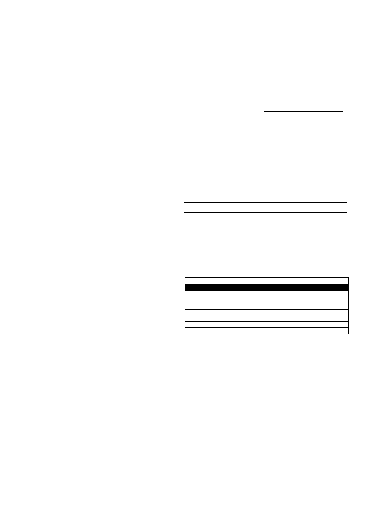
D) CODE MOT. 2 Def. 1 Input Sync Def. 2 Input Sync
E) CODE SENS. Def. 1 Input NO Sync Def. 2 Input NO Sync
ated
G)SUN/RAIN INPUT Flashing light ON/OFF alternated
by programming only the Up button.
Code programming of the “ BeFree ” radio controls is carried
out in the following manner: press the SEL button until the
CODE ALL MOT LED starts flashing. At the same time press
the UP button of the desired radio control. The CODE ALL
MOT LED will remain on and the programming is complete. If
all available radio controls have been memorised, by repeating
the programming operation, all indicator LEDs will start to flash
very fast, with the exception of the CODE ALL MOT. LED that
remains on fixed, indicating that new memorising is not possible.
Deletion Deletion of all memorised codes is carried out in the
following manner: press the SEL key, the ALL MOT. CODE
LED will start to flash, subsequently press the SET key and
keep it pressed for more than 2 seconds. The ALL MOT.
CODE LED will switch off and the procedure will be complete.
Radio control signal already in memory:
If the user attempts to perform the programming procedure for
a radio control which is already stored in the memory, the
CODE ALL MOT. LED will begin to flash rapidly for a few moments, to indicate that this procedure cannot be performed.
The unit then returns to the programming stage once again.
3) CODE MOT. 1 (programming the radio control to control
Motor 1)
Proceed as described in point 2) CODE ALL MOT. for programming the radio control related to motor 1 by selecting the
CODE MOT. LED. 1.
4) CODE MOT. 2 (programming the radio control to control
Motor 2)
Proceed as described in point 2) CODE ALL MOT. for programming the radio control related to motor 2 by selecting the
CODE MOT. LED. 2.
5) CODE SENS. (Programming the Wireless Sensors)
Programming the Wireless Sensors (Sun - Wind - Rain).
The transmission code of the Wireless Sensor is programmed
in the following manner: position with the SEL key on CODE
SENS. LED flashing and at the same time send the Wireless
Sensor code using the dedicated key located inside the Sensor: the CODE SENS. LED will remain on and the programming will be complete. If the Wireless Sensor code is not sent
within 2 minutes the control unit exits the programming phase.
Deletion.
Deletion of all memorised Wireless Sensor codes is carried out
in the following manner: press the SEL key, the CODE SENS.
LED will start to flash, subsequently press the SET key and
keep it pressed for more than 2 seconds. The CODE SENS.
LED. will switch off and the procedure will be complete.
Wireless Sensor signal already in memory:
If the control unit already has a Wireless Sensor programmed
and the user attempts to perform the programming procedure
for a Wireless Sensor again, the CODE SENS. LED will start
flashing rapidly for a few moments, signalling the impossibility.
Signal.
In case of no communication between the Wireless Sensor
and the control unit, the safety ascent of the fastening will
automatically start after 20 minutes. In case no communication
persists, further controls will always bring the control unit in
safe conditions.
6) WIND SPEED (Programming of Wind Safety threshold)
Display of the programmed Wind threshold
The display of the wind Safety threshold selection is carried out
as follows: with the SEL key position yourself on WIND SPEED
LED, the LED will start to double flash for the number of times
equal to the wind Safety threshold in the memory (to every
double flash of the WIND SPEED LED corresponds an in-
crease of 5 Km/h), (example: 5 flashes of WIND SPEED LED =
25 Km/h).
Selection of the wind Safety threshold from 5 to 40 Km/h
The sensor is supplied with the wind Safety intervention
threshold equal to 25 Km/h (WIND SPEED LED OFF).
The programming of the wind Safety threshold selection is carried out as follows: with the SEL key position yourself on WIND
SPEED LED and press the SET key to start the programming
procedure: at the same time, the WIND SPEED LED will start
to double flash; (every double flash of the WIND SPEED LED
corresponds to an increase of 5 Km/h), once the desired
threshold has been reached, press the SET key; the selected
value will be memorised at the same time and the WIND
SPEED LED will remain on (example: 5 double flashes of
WIND LED = 25 Km/h).
It is possible to repeat the operation in case of an incorrect
programming.
7) SUN / RAIN INPUT (Selection of the T1 wired Sun or Rain
Sensor input. )
The control unit is supplied by the manufacturer with the T1
input to connect a Sun Sensor, to connect a Rain Sensor instead of a Sun Sensor, proceed as follows: position the SEL
key on the flashing of LED SUN/RAIN INPUT then press the
SET key, the SUN/RAIN INPUT LED will simultaneously switch
on permanently and the programming is completed. Repeat
the procedure to restore the previous configuration.
EXTENDED MENU 1
The control unit is supplied by the manufacturer with the option
of selecting only the functions listed in the main menu.
To enable the functions of extended menu 1, proceed as follows: press and hold the SET button for 5 seconds; the T.
MOT. and WIND SPEED LED and SUN/RAIN INPUT LED will
start flashing alternately. The user then has 30 seconds in
which to select the extended menu 1 functions using the SEL
and SET buttons. After 30 seconds the control unit returns to
the main menu.
---------------------- EXTENDED MENU 1 -----------------
LED Reference LED Off LED On
A) SYNC MOTORS Step-by-Step Operator Present
B) CODE ALL MOT. Step-by-Step Venetian
C) CODE MOT. 1 Aut movements = OFF Aut movements = ON
F) WIND SPEED Flashing light ON/OFF altern
A) SYNC MOTORS (Step-by-Step or Operator Present):
The control unit is supplied by the manufacturer with Step-byStep operations, to enable the Operator Present function proceed as follows: check that the extended menu 1 is enabled
(WIND SPEED LEDs and SUN/RAIN INPUT LEDs start flashing alternately), use the SEL button to navigate to the SYNC
MOTORS LED when flashing and press the SET button: the
SYNC MOTORS LED remains lit in a constant manner and
programming is complete. Using the radio control and the push
button panel, it is necessary to maintain the command constantly activated to obtain fastening movement. The movement
always stops when the control is released. Repeat the procedure to restore the previous configuration.
B) CODE ALL MOT. (Step-by-Step or Venetian):
The control unit is supplied by the manufacturer with Step-byStep operations, to enable the Venetian function proceed as
follows: check that the extended menu 1 is enabled (WIND
SPEED LEDs and SUN/RAIN INPUT LEDs start flashing alternately), use the SEL button to navigate to the ALL MOT. CODE
LED when flashing and press the SET button: the ALL MOT.
CODE LED remains lit in a constant manner and programming
3 Rev. 1.5 26/04/2012
Page 4
is complete. This allows to obtain Operator Present type op-
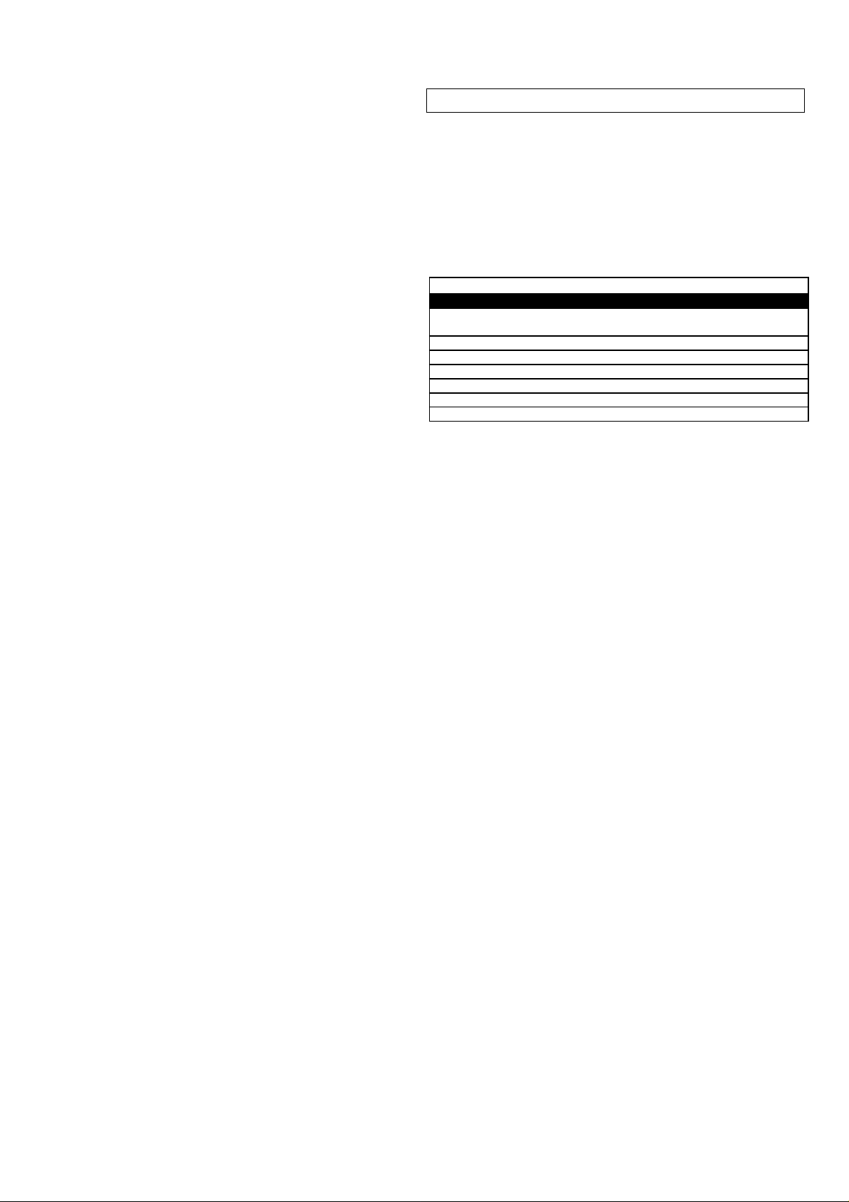
t = OFF Safety Ascent = ON
C) CODE MOT. 1 WIND Inversion = OFF WIND Inversion = ON
D) CODE MOT. 2 SUN Inversion = OFF SUN Inversion = ON
OFF RAIN Inversion = ON
F) WIND SPEED Flashing light ON/OFF simultaneous
G)SUN/RAIN INPUT Flashing light ON/OFF simultaneous
eration for the first 2 seconds, using both the radio control and
the push button panel. This way it is possible to execute slight
rotations in one direction or another for Venetian reeds in order
to modulate light filtering at will. If the controls given are
greater than 2 sec. the automatic blind ascent or descent
movement is obtained, depending on the key pressed.
Repeat the procedure to restore the previous configuration.
C) CODE MOT. 1
(Automatic Movements Lock):
The control unit allows to Lock Automatic movements (Ascent /
Descent of the blind controlled by the Sun Sensor). If during
movement, a Stop control is given via radio control, the control
unit temporarily blocks Automatic movements until the following Ascent or Descent control is given. In the control unit is
supplied by the manufacturer the Automatic movements Lock
is disabled; to enable the function proceed as follows: check
that the extended menu 1 is enabled (WIND SPEED LEDs and
SUN/RAIN INPUT LEDS start flashing alternately), use the
SEL button to navigate to the CODE MOT. 1 LED when flashing and press the SET button: the MOT. 1 CODE LED remains
lit in a constant manner and programming is complete. Repeat
the procedure to restore the previous configuration.
D) CODE MOT. 2 ( Definition of the two input modes with
Synchronised Motor Operation ) :
When Synchronised Motor operational mode is selected ( Main
menu SYNC MOTORS Led = ON ), the control unit is supplied
by the manufacturer with the following control input association. Definition 1; Synchronised Motors input:
T1 = Sun or Rain Sensor Input (N/A)
T2 = Wind Sensor Input (N/A)
T3 = MOT. 1 Ascent Local Button + MOT. 2 (N/A)
T4 = MOT. 1 Descent Local Button + MOT. 2 (N/A)
If wanting to modify input operation as follows. Definition 2;
Synchronised Motors input:
T1 = MOT. 1 Ascent Local Button + MOT. 2 (N/A)
T2 = MOT. 1 Descent Local Button + MOT. 2 (N/A)
T3 = MOT. 1 Ascent General Button + MOT. 2 (N/A)
T4 = MOT. 1 General Local Button + MOT. 2 (N/A)
proceed as follows: check that the extended menu 1 is enabled
(WIND SPEED LEDs and SUN/RAIN INPUT LEDS start flashing simultaneously), use the SEL button to navigate to the
MOT.2 CODE LED when flashing and press the SET button:
the MOT. CODE LED remains lit in a constant manner and
programming is complete. Repeat the procedure to restore the
previous configuration.
E) CODE SENS. ( Definition of the two input modes with
Independent Motor Operation ) :
When Independent Motor operational mode is selected ( Main
menu SYNC MOTORS Led = OFF), the control unit is supplied
by the manufacturer with the following control input association. Definition 1; Independent Motors input:
T1 = Sun or Rain Sensor Input (N/A)
T2 = Wind Sensor Input (N/A)
T3 = MOT. 1 Ascent/Descent Cyclical Button (N/A)
T4 = MOT. 2 Ascent/Descent Cyclical Button (N/A)
If wanting to modify input operation as follows. Definition 2; Independent Motors input:
T1 = MOT. 1 Ascent Button (N/A)
T2 = MOT. 1 Descent Button (N/A)
T3 = MOT. 2 Ascent Button (N/A)
T4 = MOT. 2 Descent Button (N/A)
proceed as follows: check that the extended menu 1 is enabled
(WIND SPEED LEDs and SUN/RAIN INPUT LEDs start flashing alternately), use the SEL button to navigate to the SENS.
CODE LED when flashing and press the SET button: the
SENS. CODE LED remains lit in a constant manner and pro-
gramming is complete. Repeat the procedure to restore the
previous configuration.
EXTENDED MENU 2
The control unit is supplied by the manufacturer with the option
of selecting only the functions listed in the main menu.
To enable the functions of extended menu 2, proceed as follows: access extended menu 1 (as described in the corresponding paragraph), then press the SET button again and
hold for 5 seconds; the WIND SPEED LEDs and SUN/RAIN
INPUT LEDs will flash simultaneously: the user has 30 seconds within which to select the functions of extended menu 2
using the SEL and SET buttons. Then after a further 30 seconds the control unit returns to the main menu.
---------------------- EXTENDED MENU 2 -----------------
LED Reference LED Off LED On
A) SYNC MOTORS Wire Sensors Test = OFF Wire Sensors Test =
ON
B) CODE ALL MOT. Safety Ascen
E) CODE SENS. RAIN Inversion =
A) SYNC MOTORS (Test Wire Sensors Test):
The control unit allows to check the operation of the connected
Sensors and that they are rotating in the correct direction.
Upon installation we suggest to put the blind in an intermediate
position in order to check the confirmation movements during
the tests. After verifying the correct functioning of the Sensors, it is necessary to disable the Wire Sensors Test.
Wired Anemometer Test: manually turn the blades of Anemometer, at the same time the control unit will trigger ascent
for 5 sec.
Wired Sun Sensor Test: expose the Sun Sensor to the sun or
a light source: at the same time the control unit will cause the
SUN/RAIN INPUT LED to flash quickly and descent for a time
equal to 5 sec. Obscure the Sun sensor, at the same moment
the control unit will cause SUN/RAIN INPUT LED to flash
slowly and the ascent for a time of 5 sec.
Wired Rain Sensor Test: wet the sensitive part of the Rain
Sensor and, at the same time, the control unit will cause the
SUN/RAIN INPUT LED to flash and the ascent for a time of 5
sec. Once completed the test, ensure the sensitive part of the
rain sensor has been dried before using the control unit as part
of the normal operations of the product.
Programming: The control unit is supplied by Wire Sensors
Test disabled. To enable the Wire Sensors Test, proceed as
follows: check that the extended menu 2 is enabled (WIND
SPEED LEDs and SUN/RAIN INPUT LEDs start flashing simultaneously), use the SEL button to navigate to the SYNC
MOTORS LED when flashing and press the SET button: the
SYNC MOTORS LED remains lit in a constant manner and
programming is complete. Repeat the procedure to restore the
initial configuration.
Important: for the Wireless Sensors test please refer to the
Wireless Sensor's manual.
B) CODE ALL MOT. (Safety Ascent):
The control unit is supplied by the manufacturer with Safety
ascent function disabled, to enable this function, so that after
12 hours of inactivity of the Wind Sensor, the control unit
automatically proceeds to perform the Safety ascent, proceed
as follows: check that the extended menu 2 is enabled (WIND
SPEED LEDs and SUN/RAIN INPUT LEDs start flashing simultaneously), use the SEL button to navigate to the ALL MOT.
CODE LED when flashing and press the SET button: the ALL
MOT. CODE LED remains lit in a constant manner and programming is complete. Repeat the procedure to restore the
previous configuration.
4 Rev. 1.5 26/04/2012
Page 5
C) CODE MOT. 1 (Movement inversion Wind Sensor):
The control unit is supplied by the manufacturer with the Wind
Safety Command = Ascent Command functioning meaning that
the sensor, when it detects wind, commands a Ascent for the
fastening. If it is desired for the sensor to command fastening
Descent when Wind is detected,, proceed as follows: check
that the extended menu 2 is enabled (WIND SPEED LEDs and
SUN/RAIN INPUT LEDS start flashing simultaneously), use the
SEL button to navigate to the CODE MOT. 1 LED when flashing and press the SET button: the MOT. 1 CODE LED remains
lit in a constant manner and programming is complete. Repeat
the procedure to restore the previous configuration.
D) CODE MOT. 2 (Movement inversion Wind Sensor):
The control unit is supplied by the manufacturer with the Rain
Command = Descent Command association meaning that the
sensor, when it detects rain, commands a Descent for the fastening. If it is desired for the sensor to command fastening Ascent when rain is detected, proceed as follows: check that the
extended menu 2 is enabled (WIND SPEED LEDs and
SUN/RAIN INPUT LEDS start flashing simultaneously), use the
SEL button to navigate to the CODE MOT. 1 LED when flashing and press the SET button: the MOT. 2 CODE LED remains
lit in a constant manner and programming is complete. Repeat
the procedure to restore the previous configuration.
E) CODE SENS. (Movement inversion Rain Sensor):
The control unit is supplied by the manufacturer with the Rain
Command = Descent Command association meaning that the
sensor, when it detects rain, commands a Descent for the fastening. If it is desired for the sensor to command fastening
Ascent when rain is detected, proceed as follows: check that
the extended menu 2 is enabled (WIND SPEED LEDs and
SUN/RAIN INPUT LEDs start flashing simultaneously), use the
SEL button to navigate to the SENS. CODE LED when flashing
and press the SET button: the SENS. CODE LED remains lit in
a constant manner and programming is complete. Repeat the
procedure to restore the previous configuration.
R
ESET
In case it is necessary to reset the control unit default factory
configuration, press the SEL and SET keys together and hold
them for more than 2 seconds so that all indicator LEDs switch
on and off at the same time.
I
MPORTANT FOR THE INSTALLER
The control unit has been designed to allow the installer to
automate devices such as sun blinds and rolling window shutters in order to submit to regulatory prescriptions in force. The
effective compliance with the obligations and achievement of
the minimal safety requirements are, however, the responsibility of the installer.
Installation must be carried out in compliance with EN 603352-97 “ Safety of household and similar electrical appliances”
part 2 “ Particular requirements for drives for rolling shutters,
awnings, blinds and similar equipment”.
In this regard, realise the plant combined with this components
control unit (motor, mechanical parts, etc.) resulting conform in
satisfying the necessary safety requisites.
-The system must be disconnected from the power supply dur-
ing maintenance near automatic blinds.
-The moving parts of the drives must be installed from at least
2.5 metres from the floor.
-The fixed controls must be installed in a visible place.
-
The control unit must be permanently connected to the
power supply network and not have any type of sectioning device of the 230 Vac electric line, it will therefore be under the
care of the installer, to provide the plant with a sectioning device. It is necessary to install a single-phase switch with overvoltage category III. It must be positioned so as to be protected against accidental closures.
- For connections (power supply, motors output), use flexible
cables under insulating sheath in harmonised polychloroprene
(H05RN-F) with minimum section of the conductors equal to
0.75 mm
- The connection cables must be fixed by assembling cable
clamps supplied with the product.
- In choosing the motor to combine with the control unit, keep
to the maximum power indications contained in this manual.
− For a correct functioning of the radio receiver, in case of us-
− If there are two ore more control units, in order to avoid ra-
2
.
ing one or more control units, the installation at a minimum
distance of at least 3 meters one from the other is recommended.
dio interference, it is recommended using only one Wireless
type Sensor.
I
MPORTANT FOR THE INSTALLER
- The device must never be used by children or persons with
reduced physical-psychological abilities, unless supervised or
trained on the functioning and the use modalities.
- Do not allow children to play with the device and keep the radio-controls away from their reach.
- ATTENTION: keep this instruction manual and respect the
important safety prescriptions contained herein. The non compliance with the prescriptions may cause damages and serious
accidents.
- Frequently examine the plant to detect any signs of damaging. Do not use the device if a repair intervention is necessary.
Attention
All operations which require the opening of the casing (cables
connection, programming, etc.) must be carried out by expert
personnel during installation. For any further operation which
requires the casing to be re-opened (re-programming, repair or
installation amendments) contact the after-sales assistance.
5 Rev. 1.5 26/04/2012
Page 6
the products:
LG2247 – LRS2247 – LRS2247 SET – LRH2247
comply with the specifications of the R&TTE Directives
99/5/EC, EMC 2004/108/EC, LVD 2006/95/EC Directives.
6 Rev. 1.5 26/04/2012
 Loading...