


OPERATOR’S MANUAL • Manual del usuario
6V/12V Battery Charger & Engine Starter
6V/12V Cargador de Batería & Arranque de Máquina
Model/Modelo
28.71225
Read and follow all safety rules and operating instructions before every use of this product.
Save these instructions.
Lea todas las instrucciones de operación y reglas de seguridad, así mismo aplíquelas a cada uso del producto.
GUARDE ESTAS INSTRUCCIONES.
Sears Brands Management Corporation, Hoffman Estates, IL 60179 U.S.A.
0099001213-00
DieHard THREE-Year Full Warranty
When operated and maintained according to all supplied instructions, if this DieHard product fails due to a defect in material or workmanship within 3 years from the date of purchase, return it to any DieHard outlet in the United States for free replacement.
This warranty gives you specific legal rights, and you may also have other rights which vary from state to state.
Sears Brands Management Corporation, Hoffman Estates, IL 60179
For customer assistance or replacement parts, call toll-free from 7 am to 5 pm CT
Monday through Friday: 1-800-732-7764
TRES AÑOS DE GARANTÍA TOTAL EN DIEHARD
Cuando se opere o maneje con las debidas precauciones de acuerdo a las instrucciones, si el DieHard falla en alguno de sus componentes de fabricación durante el 3 años contados a partir de la fecha de compra, regresarlo al autoservicio diehard en los estados unidos para reemplazar el aparato sin costo alguno.
Esta garantía le otorga derechos legales específicos, así como otros derechos que varían de estado a estado.
Sears Brands Management Corporation, Hoffman Estates, IL 60179
ASISTENCIA AL CLIENTE O REPOSICIÓN DE PARTES,
SERVICIO DE 7 AM A 5 PM, HORA CENTRO
DE LUNES A VIERNES: 1-800-732-7764

IMPORTANT: READ AND SAVE THIS SAFETY AND INSTRUCTION MANUAL.
SAVE THESE INSTRUCTIONS – This manual will show you how to use your charger safely and effectively. Please read, understand and follow these instructions and precautions carefully, as this manual contains important safety and operating instructions. The safety messages used throughout this manual contain a signal word, a message and an icon.
The signal word indicates the level of the hazard in a situation.
Indicates an imminently hazardous situation which, if not avoided, will result in death or serious injury to the operator or bystanders.
Indicates a potentially hazardous situation which, if not avoided, could result in death or serious injury to the operator or bystanders.
Indicates a potentially hazardous situation which, if not avoided, could result in moderate or minor injury to the operator or bystanders.
Indicates a potentially hazardous situation which, if not avoided, could result in damage to the equipment or vehicle or property damage.
Pursuant to California Proposition 65, this product contains chemicals known to the State of California to cause cancer and birth defects or other reproductive harm.
1.IMPORTANT SAFETY INSTRUCTIONS – SAVE THESE INSTRUCTIONS.
This manual contains important safety and operating instructions.
RISK OF ELECTRIC SHOCK OR FIRE.
1.1Keep out of reach of children.
1.2Do not expose the charger to rain or snow.
1.3Use only recommended attachments. Use of an attachment not recommended or sold by the battery charger manufacturer may result in a risk of fire, electric shock or injury to persons or damage to property.
1.4To reduce the risk of damage to the electric plug or cord, pull by the plug rather than the cord when disconnecting the charger.
1.5An extension cord should not be used unless absolutely necessary. Use of an improper extension cord could result in a risk of fire and electric shock. If an extension cord must be used, make sure:
•That the pins on the plug of the extension cord are the same number, size and shape as those of the plug on the charger.
•That the extension cord is properly wired and in good electrical condition.
•That the wire size is large enough for the AC ampere rating of the charger as specified in section 8.
1.6To reduce the risk of electric shock, unplug the charger from the outlet before attempting any maintenance or cleaning. Simply turning off the controls will not reduce this risk.
1.7Do not operate the charger with a damaged cord or plug; have the cord or plug replaced immediately by a qualified service person. (Call customer service at: 1-800-732-7764.)
1.8Do not operate the charger if it has received a sharp blow, been dropped or otherwise damaged in any way; take it to a qualified service person. (Call customer service at: 1-800-732-7764.)
1.9Do not disassemble the charger; take it to a qualified service person when service or repair is required. Incorrect reassembly may result in a risk of fire or electric shock. (Call customer service at: 1-800-732-7764.)
•1 •
RISK OF EXPLOSIVE GASES.
1.10 WORKING IN THE VICINITY OF A LEAD-ACID BATTERY IS DANGEROUS. BATTERIES GENERATE EXPLOSIVE GASES DURING NORMAL BATTERY OPERATION. FOR THIS REASON, IT IS OF UTMOST IMPORTANCE THAT YOU FOLLOW ALL INSTRUCTIONS IN THIS MANUAL EACH TIME YOU USE THE CHARGER.
1.11To reduce the risk of a battery explosion, follow all instructions in this manual and those published by the battery manufacturer and the manufacturer of any equipment you intend to use in the vicinity of the battery. Review the cautionary markings on these products and on the engine.
1.12This charger employs parts, such as switches and circuit breakers, that tend to produce arcs and sparks. If used in a garage, locate this charger 18 inches or more above floor level.
2.PERSONAL PRECAUTIONS
RISK OF EXPLOSIVE GASES.
2.1NEVER smoke or allow a spark or flame in the vicinity of a battery or engine.
2.2Remove personal metal items such as rings, bracelets, necklaces and watches when working with a lead-acid battery. A lead-acid battery can produce a short-circuit current high enough to weld a ring or the like to metal, causing a severe burn.
2.3Be extra cautious to reduce the risk of dropping a metal tool onto the battery. It might spark or short-circuit the battery or other electrical part that may cause an explosion.
2.4Use this charger for charging LEAD-ACID batteries only. It is not intended to supply power to a low voltage electrical system other than in a starter-motor application. Do not use this battery charger for charging dry-cell batteries that are commonly used with home
appliances. These batteries may burst and cause injury to persons and damage to property.
2.5NEVER charge a frozen battery.
2.6NEVER overcharge a battery.
2.7Consider having someone nearby to come to your aid when you work near a lead-acid battery.
2.8Have plenty of fresh water and soap nearby in case battery acid contacts your skin, clothing or eyes.
2.9Wear complete eye and body protection, including safety goggles and protective clothing. Avoid touching your eyes while working near the battery.
2.10If battery acid contacts your skin or clothing, immediately wash the area with soap and water. If acid enters your eye, immediately flood the eye with cold running water for at least 10 minutes and get medical attention right away.
2.11If battery acid is accidentally swallowed, drink milk, the whites of eggs or water. DO NOT induce vomiting. Seek medical attention immediately.
3.PREPARING TO CHARGE
RISK OF CONTACT WITH BATTERY ACID. BATTERY ACID
IS A HIGHLY CORROSIVE SULFURIC ACID.
3.1If it is necessary to remove the battery from the vehicle to charge it, always remove the grounded terminal first. Make sure all of the accessories in the vehicle are off to prevent arcing.
3.2Be sure the area around the battery is well ventilated while the battery is being charged.
3.3Clean the battery terminals before charging the battery. During cleaning, keep airborne corrosion from coming into contact with your eyes, nose and mouth. Use baking soda and water to neutralize the battery acid and help eliminate airborne corrosion. Do not touch your eyes, nose or mouth.
3.4Add distilled water to each cell until the battery acid reaches the level specified by the battery manufacturer. Do not overfill. For a battery without removable cell caps, such as valve regulated lead acid batteries (VRLA), carefully follow the manufacturer’s recharging instructions.
•2 •
3.5Read, understand and follow all instructions for the charger, battery, vehicle and any equipment used near the battery and charger. Study all of the battery manufacturer’s specific precautions while charging and recommended rates of charge.
3.6Determine the voltage of the battery by referring to the vehicle owner’s manual and make sure that the output voltage selector switch is set to the correct voltage. If the charger has an adjustable charge rate, charge the battery in the lowest rate first.
3.7Make sure that the charger cable clips make tight connections.
4.CHARGER LOCATION
RISK OF EXPLOSION AND CONTACT WITH BATTERY ACID.
4.1 Locate the charger as far away from the battery as the DC cables permit.
4.2 Never place the charger directly above the battery being charged; gases from the battery will corrode and damage the charger.
4.3Do not set the battery on top of the charger.
4.4Never allow battery acid to drip onto the charger when reading the electrolyte specific gravity or filling the battery.
4.5Do not operate the charger in a closed-in area or restrict the ventilation in any way.
5.DC CONNECTION PRECAUTIONS
5.1Connect and disconnect the DC output clips only after setting all of the charger switches to the “off” position (if applicable) and removing the AC plug from the electrical outlet.
Never allow the clips to touch each other.
5.2Attach the clips to the battery and chassis, as indicated in sections 6 and 7.
6.FOLLOW THESE STEPS WHEN BATTERY IS INSTALLED IN VEHICLE
A SPARK NEAR THE BATTERY MAY CAUSE
A BATTERY EXPLOSION. TO REDUCE THE RISK OF A SPARK NEAR THE BATTERY:
6.1 Position the AC and DC cables to reduce the risk of damage by the hood, door and moving or hot engine parts. NOTE: If it is
necessary to close the hood during the charging process, ensure that the hood does not touch the metal part of the battery clips or cut the insulation of the cables.
6.2Stay clear of fan blades, belts, pulleys and other parts that can cause injury.
6.3Check the polarity of the battery posts. The POSITIVE (POS, P, +) battery post usually has a larger diameter than the NEGATIVE (NEG, N, -) post.
6.4Determine which post of the battery is grounded (connected) to the chassis (vehicle frame). If the negative post is grounded to the chassis (as in most vehicles), see step
6.5. If the positive post is grounded to the
chassis, see step 6.6.
6.5For a negative-grounded vehicle, connect the POSITIVE (RED) clip from the battery charger to the POSITIVE (POS, P, +) ungrounded post of the battery. Connect the NEGATIVE (BLACK) clip to the vehicle frame or engine block at a distance away from the battery. Do not connect the clip to
the carburetor, fuel lines or sheet-metal body
parts. Connect to a heavy gauge metal part |
NEGATIVE GROUNDED SYSTEM |
of the vehicle frame or engine block. |
• 3 •
6.6For a positive-grounded vehicle, connect the NEGATIVE (BLACK) clip from the battery charger to the NEGATIVE (NEG, N, -) ungrounded post of the battery. Connect the POSITIVE (RED) clip to the vehicle frame or engine block at a distance away from the battery. Do not connect the clip to the carburetor, fuel lines or sheet-metal body parts. Connect to a heavy gauge metal part of the vehicle frame or engine block.
6.7Connect charger AC supply cord to electrical outlet.
6.8When disconnecting the charger, turn all switches to off, disconnect the AC cord, remove the clip from the vehicle chassis and then remove the clip from the battery terminal.
6.9See CALCULATING CHARGE TIME for length of charge information.
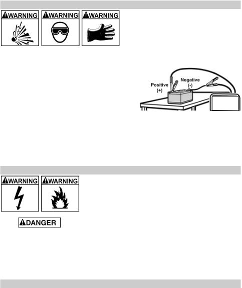
7.FOLLOW THESE STEPS WHEN BATTERY IS OUTSIDE VEHICLE
A SPARK NEAR THE BATTERY MAY CAUSE A BATTERY EXPLOSION. TO REDUCE THE RISK OF A SPARK NEAR THE BATTERY:
7.1 Check the polarity of the battery posts.
The POSITIVE (POS, P, +) battery post usually has a larger diameter than the NEGATIVE
(NEG, N, -) post.
7.2Attach at least a 24-inch (61 cm) long 6-gauge (AWG) insulated battery cable to the NEGATIVE (NEG, N, -) battery post.
7.3Connect the POSITIVE (RED) charger clip to the POSITIVE (POS, P, +) post of the battery.
7.4Position yourself and the free end of the cable you previously attached to the NEGATIVE
(NEG, N, -) battery post as far away from the battery as possible – then connect the
NEGATIVE (BLACK) charger clip to the free end of the cable.
7.5Do not face the battery when making the final connection.
7.6Connect charger AC supply cord to electrical outlet.
7.7When disconnecting the charger, always do so in the reverse order of the connecting procedure and break the first connection while as far away from the battery as practical.
7.8A marine (boat) battery must be removed and charged on shore. To charge it onboard requires equipment specially designed for marine use.
8.Grounding and AC power cord connections
RISK OF ELECTRIC SHOCK OR FIRE.
8.1 This battery charger is for use on a nominal 120-volt circuit. The charger must be grounded to reduce the risk of electric shock. The plug must be plugged into an outlet that is properly installed and grounded in accordance with all local codes and ordinances. The plug pins must fit the receptacle (outlet). Do not use with an ungrounded system.
8.2Never alter the AC cord or plug provided – if it does not fit the outlet, have a proper grounded outlet installed by a qualified electrician. An improper connection can result in a risk of an electric shock or electrocution. NOTE: Pursuant to Canadian Regulations, use of an adapter plug is not allowed in Canada. Use of an adapter plug in the United States is not recommended and should not be used.
8.3Recommended minimum AWG size for extension cord:
•100 feet long (30.5 meters) or less – use a 12 gauge (3.31 mm2) extension cord.
•Over 100 feet (30.5 meters) long – use a 10 gauge (5.26 mm2) extension cord.
9.ASSEMBLY INSTRUCTIONS
9.1Remove all cord wraps and uncoil the cables prior to using the battery charger.
9.2Included with your battery charger are two cord wrap cleats for storage of the battery cables. To install, align the three tabs to correspond with the three receptacles on the back of the charger and push until you hear a snap.
•4 •
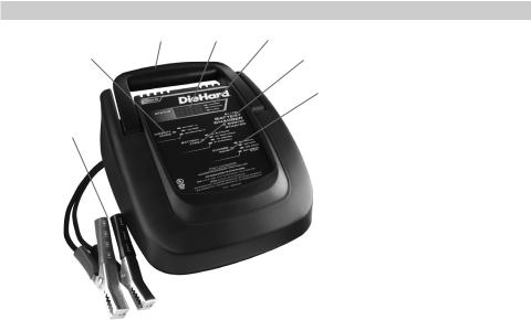
10. FEATURES/Control Panel
1 |
6 |
2 |
3 |
|
4 |
5
1. Carrying Handle
7 2. Charger Status LEDs
3. Display Mode Button
4. Battery Type Button
5. Charge Rate Button
6. Digital Display
7. Battery Clips
LED Indicators
CHECK BATTERY (red) LED lit: Indicates the charger is not properly connected to the battery.
CHECK BATTERY (red) LED blinking: Indicates the charger is in abort mode. CHARGING (yellow) LED lit: Indicates the charger is charging the battery.
CHARGED (green) LED lit: Indicates the battery is fully charged and the charger is in maintain mode.
NOTE: See the Operating Instructions section for a complete description of the charger modes.
Digital Display
The Digital Display gives a digital indication of voltage of the battery, % of charge of the battery or % of charging output of the alternator, depending on the Display Mode chosen.
Display Mode Button
Use this button to set the function of the digital display to one of the following:
•Battery % – The digital display shows an estimated charge percentage of the battery connected to the charger battery clips. The percent indicated is an estimate based on the present battery voltage. Connecting and reconnecting a battery during charging or after charging is complete will cause the charger to recalculate the percentage and may display a different percentage than was previously indicated.
•Voltage – The digital display shows the voltage at the charger battery clips in DC volts. Keep in mind that this reading is only a battery voltage reading, and a false surface charge may mislead you. We suggest that you turn on the headlights for a couple of minutes before you read the meter. Read it a couple of minutes after you have shut the headlights off. If the reading is less than 10.5 volts (5.2 volts for 6V battery), the battery may be bad or the connection at the charger may be poor. If the reading is 10.5 volts to 12.8 volts (5.2 volts to 6.4 volts for 6V battery), the battery is low – recharge it. If the reading is above 12.8 volts (6.4 volts for 6V battery) the battery is charged. NOTE: The voltage display is not available during charging, and the digital display will default to BATTERY %.
•Alternator % – The digital display shows an estimated output percentage of the vehicle’s charging system connected to the charger battery clips as compared to a properly functioning system. The alternator percent range is from 0 to 100%. Readings below 0 (13.2 volts) will read LO and readings above 100% (14.6 volts) will read
HI. If you get a HI or LO reading, have the electrical system checked by a qualified technician. The percent indicated is an estimate based on the present alternator output.
•5 •

Battery Type Button
Use this button to set the type of battery to be charged.
•Standard – Set the button to 12V STANDARD or 6V STANDARD.
•Deep-Cycle – Set the button to 12V DEEP CYCLE.
•AGM – Set the button to 12V AGM/GEL.
•GEL – Set the button to 12V AGM/GEL.
Charge Rate Button
Use this button to set the maximum charge rate.
•2A Slow Charge Rate – Intended for charging small batteries such as those commonly used in garden tractors, snowmobiles and motorcycles.
•12A Fast and 30A Rapid Charge Rate – Use for charging automotive, marine and deep-cycle batteries. Not intended for industrial applications.
•80A Engine Start – Provides 80 amps for cranking an engine with a weak or run down battery. Always use in combination with a battery.
11.OPERATING INSTRUCTIONS
 This battery charger must be properly assembled in accordance with the assembly instructions before it is used.
The charger does not have an On/Off switch. The On and Off commands are controlled by plugging the 71225 into a 120V AC electrical wall outlet only after the battery connections have been made.
Charging
1.Ensure that all of the charger components are in place and in good working condition, for example, the plastic boots on the battery clips.
2.Connect the battery following the precautions listed in sections 6 and 7.
3.Connect the AC power, following the precautions listed in section 8.
4.Select the appropriate settings for your battery.
NOTE: This charger is equipped with an auto-start feature. It will not supply current to the battery clips until a battery is properly connected. Meaning, the clips will not spark if touched together.
Battery Connection Indicator
If the charger does not detect a properly connected battery, the CHECK (red) LED will light. Charging will not begin if the CHECK (red) LED is on.
Automatic Charging Mode
When an Automatic Charge is performed, the charger switches to the Maintain Mode
(see below) automatically after the battery is charged. For a battery with a starting voltage under 0.1 volt, the charger will not recognize that the battery is connected and the CHECK (red) LED will stay lit. In order to charge the battery, use a manual charger to pre-charge the battery for five minutes to get additional voltage into the battery.
Aborted Charge
If charging cannot be completed normally, charging will abort. When charging aborts, the charger’s output is shut off, the CHECK (red) LED will blink and the digital display will show a failure code (see the TROUBLESHOOTING section for a description of the failure codes). In that state, the charger ignores all buttons. To reset after an aborted charge, unplug the charger, wait a few moments, then plug it back in.
Desulfation Mode
If the battery is left discharged for an extended period of time, it could become sulfated and not accept a normal charge. If the charger detects a sulfated battery, the charger will switch to a special mode of operation designed for such batteries. If successful, normal charging will resume after the battery is desulfated. Desulfation could take 8 to 10 hours. If desulfation fails, charging will abort, the CHECK (red) LED will blink and the digital display will show a failure code of F02 (bad battery).
• 6 •
Completion of Charge
Charge completion is indicated by the CHARGED (green) LED. When lit, the charger has switched to the Maintain Mode of operation. If the 12V DEEP CYCLE battery type was selected, the CHARGED (green) LED comes on when the battery is charged enough for normal use.
Maintain Mode (Float-Mode Monitoring)
When the CHARGED (green) LED is lit, the charger has started Maintain Mode. In this mode, the charger keeps the battery fully charged by delivering a small current when necessary. The voltage is maintained at a level determined by the BATTERY
TYPE selected.
NOTE: The maintain mode technology utilized in DieHard chargers allows you to safely charge and maintain a healthy battery for extended periods of time. However, problems with the battery, electrical problems in the vehicle, improper connections or other unanticipated conditions could cause excessive voltage draws. As such, occasionally monitoring your battery and the charging process is recommended.
Using the Engine Start feature
Your battery charger can be used to jumpstart your car if the battery is low. Follow these instructions on how to use the ENGINE START feature.
 Follow all safety instructions and precautions for charging your battery. Wear complete eye protection and clothing protection. Charge your battery in a wellventilated area.
 Using the ENGINE START feature WITHOUT a battery installed in the vehicle could cause damage to the vehicle’s electrical system. NOTE: If you have charged the battery and it still will not start your car, do not use the engine start feature, or it could damage the vehicle’s electrical system.
1.With the charger unplugged from the AC outlet, connect the charger to the battery following the instructions given in section 6: FOLLOW THESE STEPS WHEN BATTERY IS INSTALLED IN VEHICLE.
2.Plug the charger AC power cord into the AC outlet.
3.With the charger plugged in and connected to the battery of the vehicle, set the charge rate selector button to the engine start position.
4.When the display shows rdy, crank the engine until it starts or 3 seconds pass. If the engine does not start, wait 3 minutes until the display shows rdy before cranking again. This allows the charger and battery to cool down.
NOTE: During extremely cold weather, or if the battery is under 2 volts, charge the battery for 5 minutes before cranking the engine.
5.If the engine fails to start, charge the battery for 5 more minutes before attempting to crank the engine again.
6.After the engine starts, unplug the AC power cord before disconnecting the battery clips from the vehicle.
7.Clean and store the charger in a dry location.
NOTE: If the engine does turn over but never starts, there is not a problem with the starting system; there is a problem somewhere else with the vehicle. STOP cranking the engine until the other problem has been diagnosed and corrected.
Engine Starting Notes
During the starting sequence listed above, the charger is set to one of the following three states:
Wait for cranking – The charger waits until the engine is actually being cranked before delivering the 80 amps for engine start. The charger delivers charge at a rate of up to 12 amps while waiting. While waiting for cranking, the digital display will show rdy.
Cranking – When cranking is detected, the charger will automatically deliver up to its maximum output as required by the starting system for up to 3 seconds or until the engine cranking stops. The digital display shows a countdown of the remaining crank time in seconds. It starts at 3 and counts down to 0.
• 7 •
 Loading...