

Sistemi Elettronici
di Apertura Porte e Cancelli
International registered trademark n. 804888
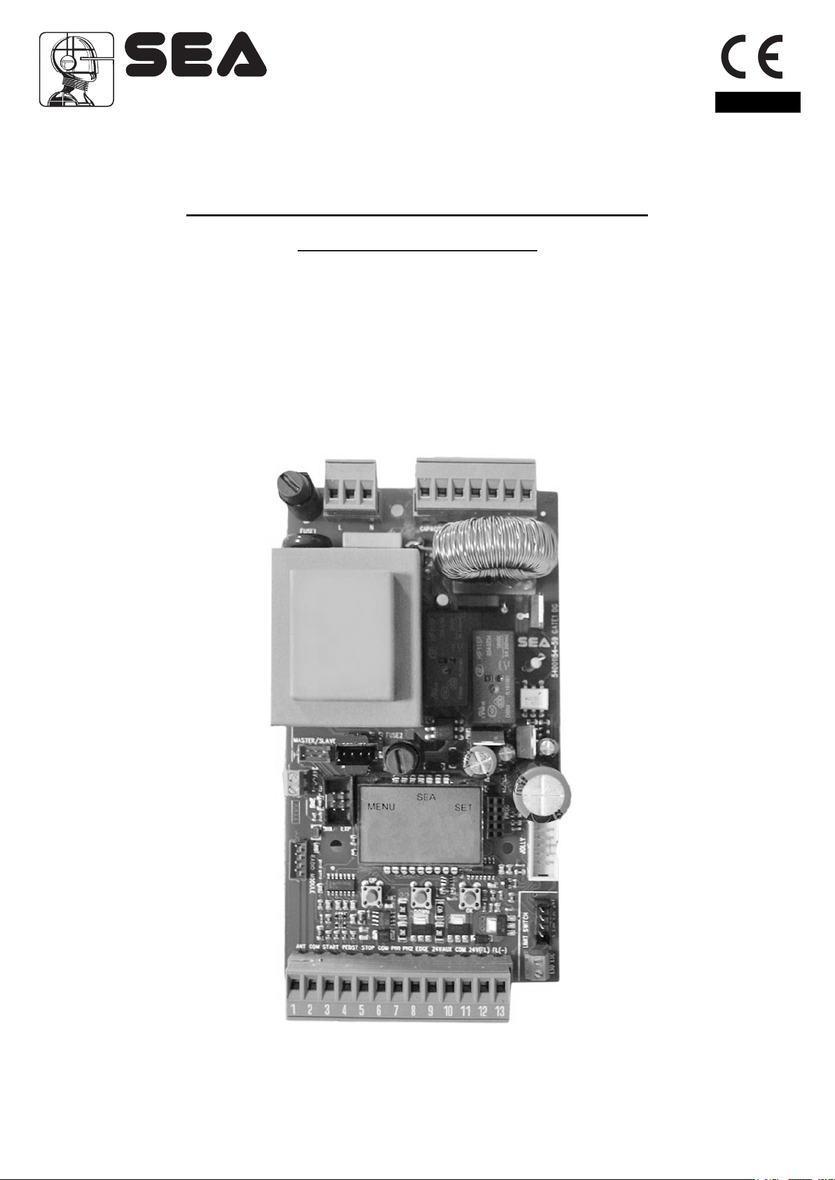
GATE 1 DG R2BF
CONTROL UNIT FOR SLIDING GATES
®
English
With inverter module
(Cod. 23001235)
67411665
Rev.05 - 06/2016
®
English
Sistemi Elettronici
di Apertura Porte e Cancelli
International registered trademark n. 804888
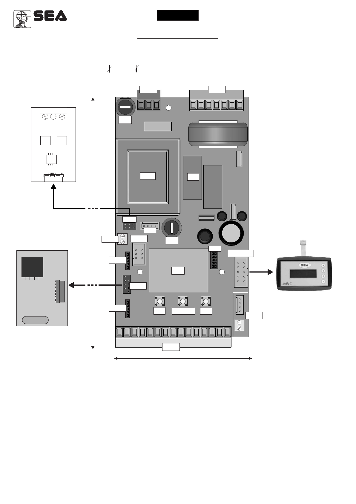
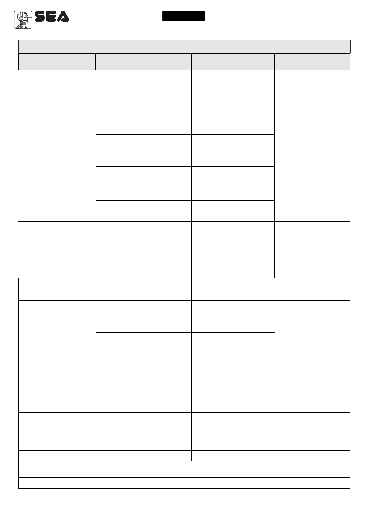
COMPONENTS
TECHNICAL SPECIFICATIONS
Control unit power supply: 230 Vac Single-phase
Absorption in stand by: 30 mA
Environment temperature : -20°C +50°C
Specifications of external enclosure: 183 X 238 X 120 - IP55
INTERFACE CARD
SIGB
COM
SIGA
F1
GATE 1 DG R2BF
INVERTER
CN2CN3
RECEIVER RX
CN4
155 mm
CNS
CNS
CMS
EXP
CNA
Tr1
CN5
F2
DS
UP DOWN OK
CN1
R1
CNP
JOLLY3
JOLLY 3
CN6
85 mm
CN1 = Input/output connectors
CN2 = Courtesy light connector
CN3 = Power connector
CN4 = 24V~ connector
CN5 = Inverter control connector
CN6 = Limit switch connectors
CNA = Receiver connector RX
CNP = Programming connector
CNS = RF FIX Receiver connector
EXP = Expansion module connector -
JOLLY 3 = Jolly 3 connector
DS = Programming display
CMS = Inverter interface connector
OK = Programming button
DOWN = Programming button
UP = Programming button
R1 = Relay C motor command Courtesy light
F1 = 6.3AT fuse on 230V
F2 = Accessories 1A fuse
Tr1 = Power transformer
LSE card
2
Sistemi Elettronici
di Apertura Porte e Cancelli
International registered trademark n. 804888
®
English
GATE 1 DG R2BF
INVERTER
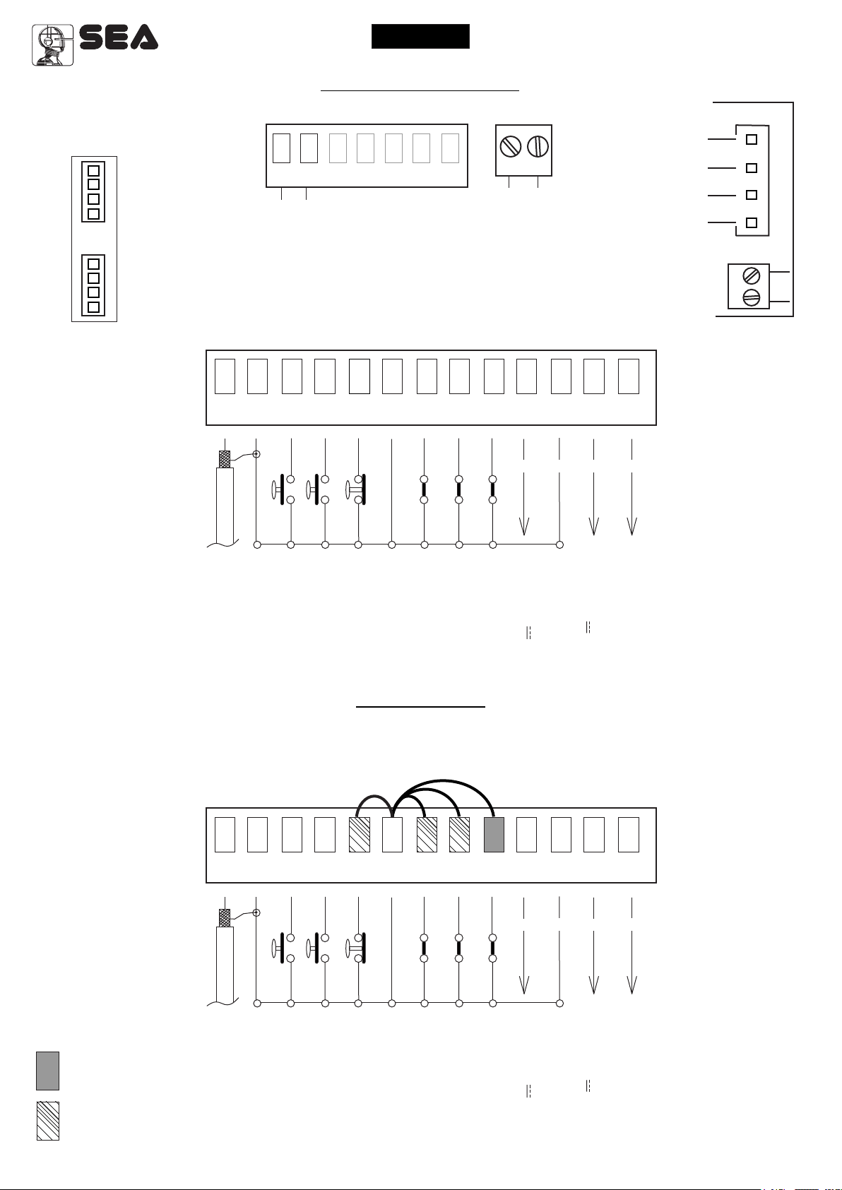
CONNECTIONS
RADIO MODULE RF FIX
(CNS)
RF FIX
Receiver
connector
(Available from
hardware
revision R2)
1
ANT COM START
2
15
14
Flash Light
3 4
CN2
16 17
Flash N
5 6
PEDST
STOP COM PH1 PH2
18 19
CN1
7 8
20
CN4
24Vac
Max 150 mA
9
10
EDGE
24VAUX
Limit switch Closing 1 (Yellow)
Limit switch Opening 1 (Green)
Limit switch Closing 1 (Yellow)
Limit switch Opening 1 (Green)
12
11
COM 24V(FL) (FL)-
- -
+ +
13
24V (Red)
Common (White)
Nota: The connectors
CN6 and CN7 are not
used if the Four limit
switch interface card is
connected.
CN6
LIMIT SWITCH
1
CN7
Stop
START Pedestrian
Common
Photocell 1
Photocell 2
Safety edge 1
AUX Programmable
(24V 500 mA max)
Common
(Accessories)
24V 500 mA max
Flash (-)
Antenna
Common
Start
JUMPERS
WARNING: The control unit is designed with the automatic detection of not used N.C. inputs (Photocells, Stop and Limit
switch) except the SAFETY EDGE input. The exclude inputs in self-programming can be restored in the “Check inputs”
menu without need to repeat the programming (page 11).
CN1
2
1
ANT COM START
3 4
5 6
PEDST
STOP COM PH1 PH2
7 8
9
EDGE
10
11
24VAUX
COM 24V(FL) (FL)-
- -
+ +
12
13
Obligatory jumper
without accessory
connection.
Optional
Antenna
Common
Start
Stop
START Pedestrian
Common
Photocell 1
Photocell 2
Safety edge 1
AUX Programmable
(24V 500 mA max)
Common
(Accessories)
24V 500 mA max
Flash (-)
The herein reported
f u n c t i o n s a r e
available st a r t i n g
from: revision 01.07
c o m p a t i b l e w i t h
JOLLY 3.
3
Sistemi Elettronici
di Apertura Porte e Cancelli
International registered trademark n. 804888
MENU
1
LANGUAGE
MENU
2
TRANSMITTERS
MENU
3
MOTOR
MENU
5
REVERSE
MOTOR
UP
SEA
UP
SEA
UP
SEA
UP
SEA
UP
®
SET
OK
SEA
MENU
ITALIANO
SET
Skip this step if you do not want to program a transmitter
SET
OK
If on the display
appears the item:
SET
OK
SET
OK OK
SEA
MENU
START
SET
MENU
RECEIVER
MISSING
OK
SEA
Choose the type of
motor with
UP or DOWN
Choose ON with
UP or DOWN
if you want to reverse
the direction of
the motor rotation
English
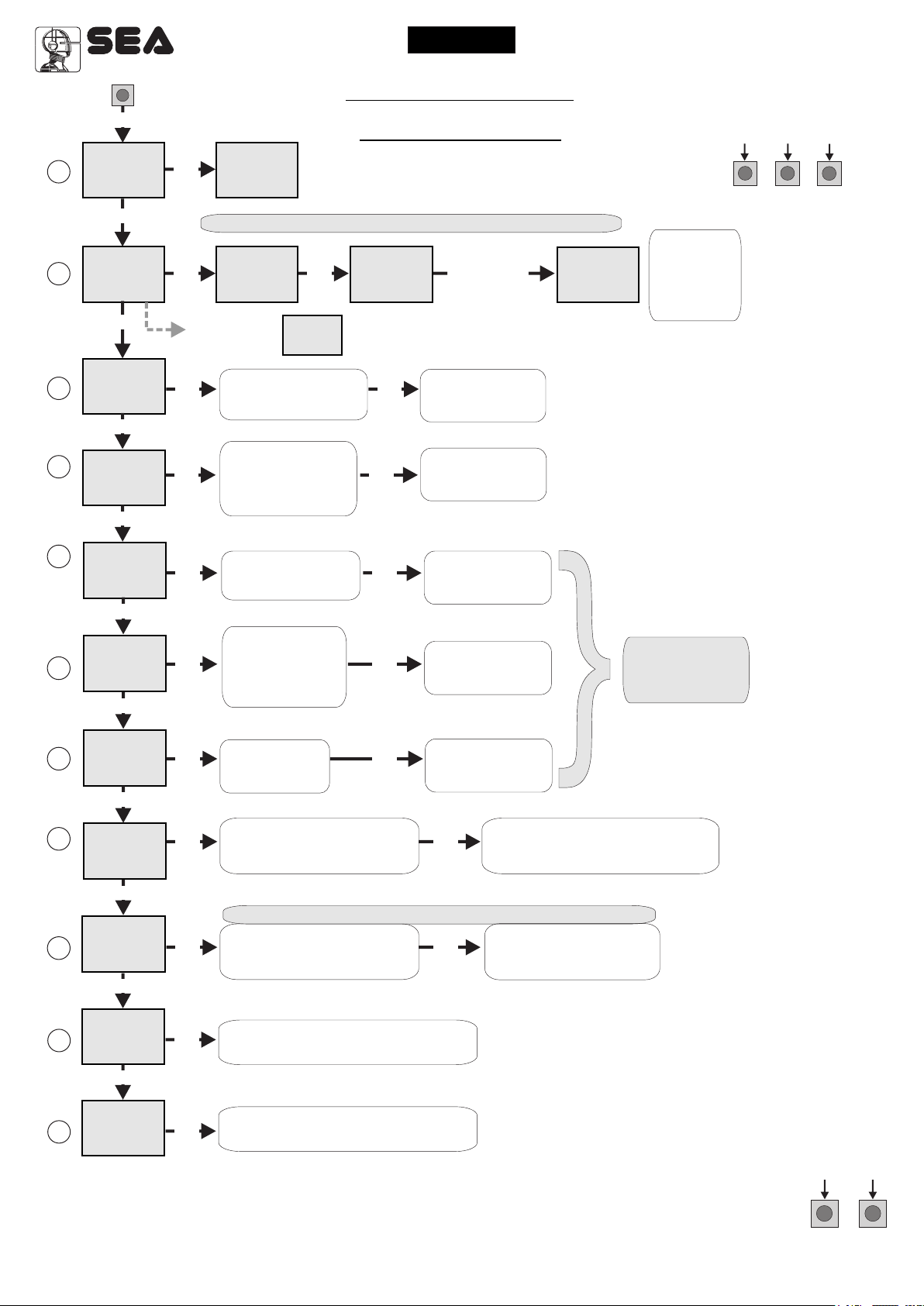
PROGRAMMING
QUICK START
SEA
MENU
PRESS
BUTTON
Check if a receiver has
SET
been connceted
(see page 2)
OK
SET
Press the
button of the
TX to be
stored
To confirm and return
to main menu
Per confermare
e tornare
al Menu principale
MENU
STORED
SEA
SET
Menu or press
the next TX to
GATE 1 DG R2BF
INVERTER
PROGRAMMING
BUTTONS
DOWNUP
OK to exit
the button of
be stored
OK
6
(See
page 5)
7
8
9
(See
page 5)
10
SEA
MENU
SET
LOGIC
UP
SEA
MENU
SET
PAUSE TIME
UP
SEA
MENU
SET
START IN
PAUSE
UP
SEA
MENU
SET
PROGRAM-
MING
UP
SEA
MENU
SET
TEST START
UP
OK OK
choose
With UP or DOWN
To confirm and return
the desired logic
OK OK
choose a delay for
With UP or DOWN
To confirm and return
automatic closing
OK OK
With UP or DOWN
To confirm and return
Choose ON
OK OK
With UP or DOWN choose ON
to start times learning
The gate will execute a CLOSING-OPENING-CLOSING CYCLE
Skip this step if a TX has already been stored
OK OK
UP or DOWN Choose
With
ON to start test
to main menu
to main menu
to main menu
the control unit returns automatically
To confirm and return to
Skip this step
if you want to work
in half-automatic
logic
At the end of the selflearning
to the main menu
main menu
SEA
MENU
15
END
SET
OK
Press OK to return to the
display of the inputs state.
UP
SEA
16
MENU
SPECIAL
MENU
SET
OK
Press OK to enter the special menu.
ALL OTHER PARAMETERS HAVE DEFAULT SETTINGS WHICH ARE USEFUL FOR THE 90% OF
THE APPLICATIONS BUT CAN BE HOWEVER SET THROUGH THE SPECIAL MENU. FOR
ENTERING INTO THE SPECIAL MENU MOVE ON ONE OF THE MENU AND PRESS THE UP
AND DOWN BUTTONS AT THE SAME TIME FOR 5 S.
4
UPDOWN
Sistemi Elettronici
di Apertura Porte e Cancelli
International registered trademark n. 804888
®
English
GATE 1 DG R2BF
INVERTER
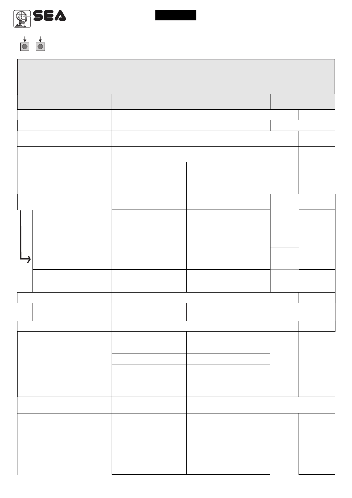
MENU FUNCTIONS TABLE GATE 1 DG R2BF
MENU
1 - LANGUAGE
2 - TRANSMITTERS
3 - MOTOR
For single-phase version only
SET
Italiano
English
Français
Español
Dutch
Start
Pedestrian Start
External module
Stop
Unloch
Delete a transmitter
Clear memory
End
Barrier
Centralina idraulica
Lepus Fast
Big Fast - Super Fast
Description
Italian
English
French
Spanish
Olandese
Start
Pedestrian Start
External module
Stop
Storing of a command
for unlocking an
electric brake
Delete single transmitter
Delete transmitter memory
“Transmitters” menu output
Barrier
Hydraulics units
Lepus Fast
Big Fast - Super Fast
Default
English
Start
Pedestrian
Start
Barrier
Set value
3 - MOTOR
For three-phase version only
5 - REVERSE MOTOR
6 - LOGIC
(See page 6)
7 - PAUSE TIME
8 - START IN PAUSE
9 - PROGRAMMING
(See page 6)
Big
Sliding
Sliding Fast
Off
On
Automatic
Open-stop-close-stop-open
Open-stop-close-open
2 buttons
Safety
Dead man
Off
1 240
Off
On
Off On
Big
Sliding
Sliding Fast
Synchronized right motor
Synchronized left motor
Automatic
Step by step type 1
Step by step type 2
Two buttons
Safety
Dead man
OFF
(semi-automatic logics)
Setting from 1s to 4min.
In pause start is not acceped
In pause start is accepted
Times learning start
Sliding
Off
Automatic
Off
Off
Off
10 - TEST START
15 - END
16 - SPECIAL MENU
Off On
Press OK to return to the display of the firmware version
Press OK to enter the special menu.
Start command
and to the one of inputs state.
Note: In case of three-phase version, the motors are: “Sliding” and “Sliding Fast”.
Off
5

Sistemi Elettronici
di Apertura Porte e Cancelli
International registered trademark n. 804888
®
English
GATE 1 DG R2BF
INVERTER
WORKING TIMES SELF LEARNING
1) Turn off electricity, release the motors and manually position the leaves on halfway.
Reset the mechanical lock.
2) Connect the control board to the power supply.
3) Before starting the learing, make sure (through the test menu), that the relative limit switches of every opening are
employed.
4) Select on the on-board display or JOLLY 3 programmer, the type of motor that you are using as indicated in the
dispaly management.
5) If necessary also set the operation logic and the other parameters. If you want to program with a transmitter, store a
transmitter before programming.
6) Select 9-PROGRAMMING on the display, press OK and than one of the UP or DOWN buttons.
(If the motor starts in opening, remove and re-put power supply, select on the display 5-REVERSE MOTOR.
And through the UP and DOWN button put it on ON, or if you have the Jolly 3 programmer, activate the motor
exchange function. )
7) At this point the gate will start the following cycle: CLOSING - OPENING - CLOSING.
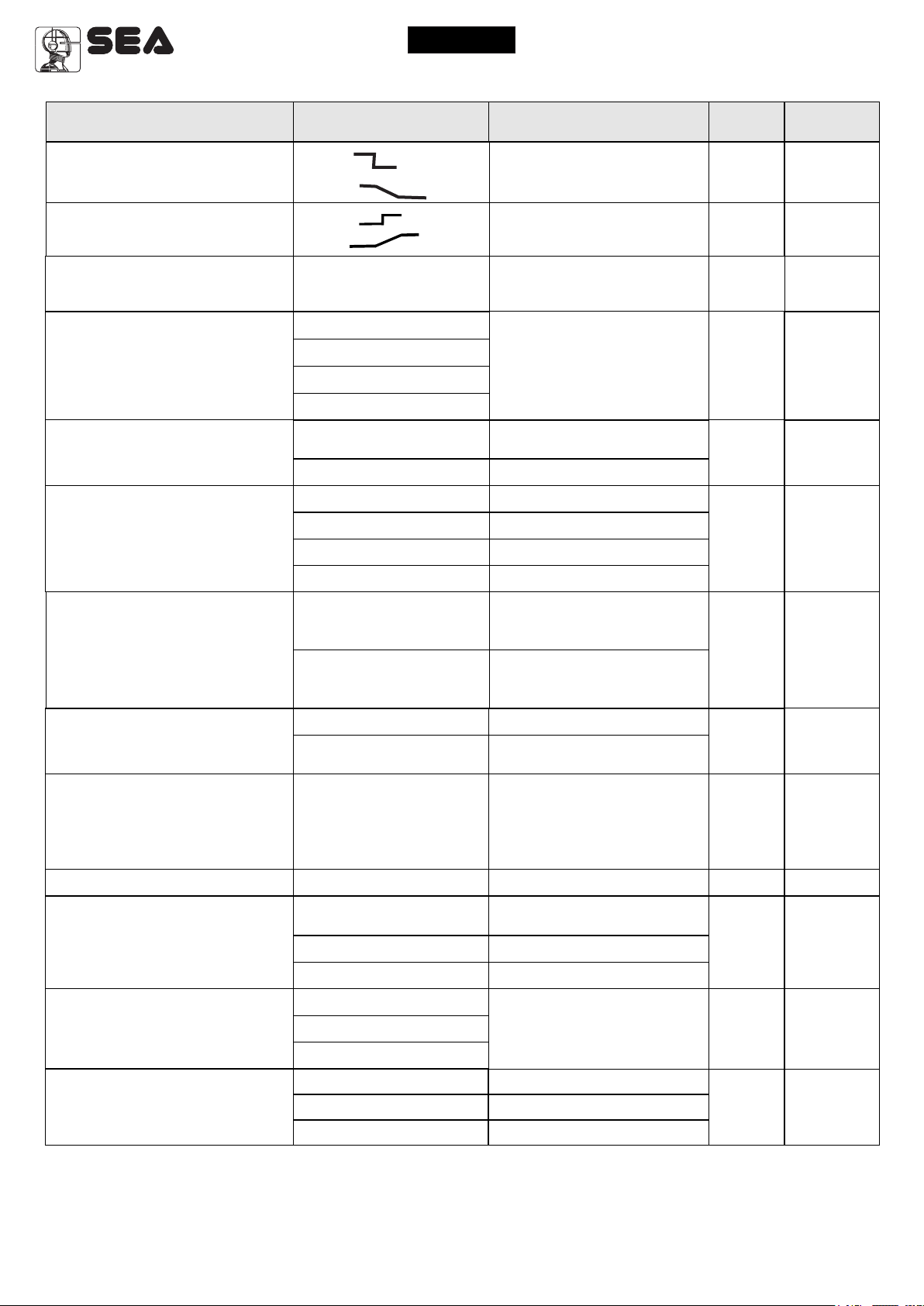
FUNCTION LOGIC
AUTOMATIC LOGIC
A start impulse opens the gate. A second impluse during the opening will not be accepted.
A start impulse during closing reverses the movement.
NOTE 1: To have the automatic closing it is necessary to set a pause time, otherwise all the logic will be semiautomatic.
NOTE2: It is possible to choose, whether to accept or not, the start in pause, selecting in the MENU the item
8-START IN PAUSE and choosing ON or OFF. By default, the parameter is OFF.
SECURITY LOGIC
A start impulse opens the gate. A second impulse during opening reverses the movement.
A start impulse during closing reverses the movement.
NOTE 1: To have the automatic closing it is necessary to set a pause time, otherwise all the logic will be semiautomatic.
NOTE2: It is possible to choose, whether to accept or not, the start in pause, selecting in the MENU the item
8-START IN PAUSE and choosing ON or OFF. By default, the parameter is OFF.
STEP BY STEP TYPE 1 LOGIC
The start impulse follows the OPEN-STOP-CLOSE-STOP-OPEN logic.
NOTE 1: To have the automatic closing it is necessary to set a pause time, otherwise all the logic will be semiautomatic.
NOTE2: It is possible to choose, whether to accept or not, the start in pause, selecting in the MENU the item
8-START IN PAUSE and choosing ON or OFF. By default, the parameter is OFF.
STEP BY STEP TYPE 2 LOGIC
The start impulse follows the OPEN-STOP-CLOSE -OPEN logic.
NOTE 1: To have the automatic closing it is necessary to set a pause time, otherwise all the logic will be semiautomatic.
NOTE2: It is possible to choose, whether to accept or not, the start in pause, selecting in the MENU the item
8-START IN PAUSE and choosing ON or OFF. By default, the parameter is OFF.
DEAD MAN LOGIC
The gate opens as long as the START button of opening is pressed; releasing it the gate stops. The gate closes as
long as the button connected to the PEDESTRIAN START is pressed; releasing it the gate stops. To execute
complete opening and/or closing cycles the related pushbuttons must be constantly pressed.
2 PUSHBUTTONS LOGIC
One start opens, one pedestrian start closes. In opening the closing will not be accepted. In closing a start command
reopens, a pedestrian start command (closes) will be ignored.
6
Sistemi Elettronici
di Apertura Porte e Cancelli
International registered trademark n. 804888
®
English
GATE 1 DG R2BF
INVERTER
SPECIAL MENU
PRESS AT THE SAME TIME FOR 5 SECONDS TO ENTER OR TO EXIT THE SPECIAL MENU
UPDOWN
SPECIAL MENU FUNCTIONS TABLE GATE 1 DG R2BF INVERTER
For entering into the special menu move on one of the menu and press the UP and DOWN
buttons at the same time for 5 s. For exiting the special menu press END or move on one of the
menu and press the UP and DOWN buttons at the same time for 5 s.
MENU SP
17 - OPENING SPEED
18 - CLOSING SPEED
21 - OPENING SLOWDOWN
SPEED 1
22 - CLOSING SLOWDOWN
SPEED 1
28 - OPENING A THRESHOLD *
For three-phase version only
29 - CLOSING A THRESHOLD *
For three-phase version only
32 - ENCODER *
51 - I.PAR.M1 *
52 - I.AP.M1 *
53 - I.CH.M1 *
32 - ENCODER *
47 - ENCODER PAR.1 *
48 - ENCODER TOT.1 *
32 - ENCODER *
33 - OPENING SENSITIVITY
MOTOR1
34 - CLOSING SENSITIVITY
MOTOR1
57 - WORKING CURRENT
59 - OPENING SLOWDOWN 1
60 - CLOSING SLOWDOWN 1
SET
10 100
10 100
10 60 from max. speed
10 60 from max. speed
1 - 5
1 - 5
Potentiometer
- - - - - - - -
- - - - - - - -
- - - - - - - -
On
xxx.
xxx.
Off
10% (Fast intervention)
99% (Slow intervention)
Off (Intervention excluded)
10% (Fast intervention)
99% (Slow intervention)
Off (Intervention excluded)
0.0A
Off 50
Off 50
Description
Setting from 10 to 100
Setting from 10 to 100
Slowdown speed in opening
Slowdown speed in closing
Adjust inversion current on
motors in opening.
Adjust inversion current on
motors in closing.
Enables the reading of the
Default
80
80
20
20
2.5
2.5
Off
Set Value
potentiometer with LE card.
Reports the current position
of the potentiometer on the
leaf. This parameter is useful
for seeing if the potentiometer
is read correctly.
Reports the impulses
stored by the control unit
when the leaf is fully open.
Reports the impulses stored
by the control unit when the
leaf of is fully close.
In ON enables the Encoder
Off
Encoder impulses during operation (Motor 1).
Encoder impulses stored in programming (Motor 1).
In OFF disabled the Encoder
Adjusts the intervention time
of the Encoder / Potentiometer
in opening
Off
95
Disabled
Adjusts the intervention time
of the Encoder / Potentiometer
in closing
95
Disabled
Shows motor absorption
during operation
From OFF to 50% of
the stroke. Note: Not active
if the Four limit switch
30
interface card is present
From OFF to 50% of
the stroke. Note: Not active
if the Four limit switch
30
interface card is present
7
Sistemi Elettronici
di Apertura Porte e Cancelli
International registered trademark n. 804888
®
English
GATE 1 DG R2BF
INVERTER
MENU SP
63 - DECELERATION
64 - ACCELERATION
70 - POSITION RECOVERY
(For three-phase version only)
79 - ANTI INTRUSION
85 - PREFLASHING
86 - FLASHING LIGHT
87 - FLASHING LIGHT
AND TIMER
88 - COURTESY LIGHT
89 - TRAFFIC LIGHT
RESERVATION
90 - PARTIAL OPENING
91 - PARTIAL PAUSE
SET
0 %
100%
1 s
5 s
0 20 s
Only opening
Only closing
Opening and closing
Off
Only closing
0.0 5.0
Normal
Light
Always
Buzzer
Off
On
In cycle
1 240
Off on
5 100%
= Start
Off
Description
Adjust the passage
between normal speed
and slowdown speed
Acceleration ramp.
Adjusts the motor start.
Retrieves the inertia of the
motor in opening and closing
after Stop or reversing
If you force the gate
manually, the control
unit starts the motor to
restore the state of the
gate before forcing.
Pre-flashing only
active before closing
Pre-flashing time
Normal
Control lamp
Always ON
Buzzer
The flashing light remains
OFF with the active timer
and open gate
The flashing light remains
ON with active timer and
open gate
Courtesy light in cycle
Courtesy light setting
from 1s to 4min.
When setting this function
the pedestrian input will be
activated to work on the
auxiliary board SEM
(traffic light management).
Setting from 5 to 100
Pause in partial opening
same as in total opening
Disabled
Default
50%
2.5 s
1 s
Off
Off
Normal
Off
20
Off
100%
= Start
Set Value
92 - TIMER
93 - FIRE SWITCH
8
1 240
Off
On photo2
On pedestrian entry
Off
On photo2
On pedestrian entry
Setting from 1s to 4 min.
Transforms the selected
input in an input on
which to connect an
external clock.
Disabled
Active on Photo 2
Active on pedestrian
Off
Off

Sistemi Elettronici
di Apertura Porte e Cancelli
International registered trademark n. 804888
®
English
GATE 1 DG R2BF
INVERTER
MENU SP
94 - 24V AUX (Programmable)
95 - AUTOTEST
97 - PHOTO1
98 - PHOTO2
SET
Always
In cycle
Opening
Closing
In pause
Autotest
In cycle and fototest
Photo1
Photo2
Photo1-2
Off
Edge
Photo1 and Edge
Photo2 and Edge
All safe
Closing
Opening
Stop
Stop and close
Close
Pause reload
Shadow loop
Closing
Opening
Stop
Stop and close
Close
Pause reload
Shadow loop
Description
AUX output always
power supplied
AUX output active only
during cycle
AUX output power
supplied only during opening
AUX output power
supplied only during closing
AUX output power
supplied only during pause
Security test
AUX output only during cycle
with fototest function active
Autotest active only on
Photo1
Autotest active only on
Photo2
Autotest active on
Photo1 and Photo2
Disabled
Autotest only on safety edge
Autotest photo 1 and
safety edge
Autotest photo 2 and
safety edge
Autotest photo 1, photo 2
and safety edge
Photocell active in closing
Active in opening
and closing
Photocell active before
opening
The photocell stops in closing
and closes when released
The photocell gives a
command to close during
opening, pause and
closing
The photocell charging the
pausing time
Until occupied, with open
gate, it prevents reclosing.
It is switched off during
closing.
Default
Always
Off
Closing
Opening
Set Value
9

Sistemi Elettronici
di Apertura Porte e Cancelli
International registered trademark n. 804888
®
English
GATE 1 DG R2BF
INVERTER
MENU SP
100 - EDGE1
102 - EDGE1
104 - SELECT LIMIT SWITCH
106 - DIAGNOSTICS
107 - MAINTENANCE CYCLES
108 - PERFORMED CYCLES
112 - PASSWORD
115 - DECELERATION RAMP
120 - BASIC MENU
Normal
SET
Normal N.C. contact
Description
Edge is active and
8K2
Opening and closing
Only opening
Only closing
Normal
Ext
1 10
100 10E4
protected by a 8k2 resistor
Active in opening
and closing
Active only in opening
Active only in closing
Limit switch in automatic
recognition
With LSE card
Shows last event
(See alarms table)
Setting from 100 to
100000
Opening
Reports the executed
0 10E9 0
cycles. Keep pressed OK
to reset the cycles
Allows the entering of a
password blocking the
- - - -
control unit parameters
modification.
1 s
Adjust the motor stop.
On heavy gates it is
5 s
recommended to set this
value to minimes 2.5s.
Press OK to exit the special menu.
The special menu switches off automatically after 20 minutes.
Default
Normal
and
closing
Normal
10E4
- - - -
- - - -
Set Value
Note 1: The * indicates that the default value or the menu may change depending on the selected motor type.
Note 2: After initialization the parameters "motor type" and "limit switch type" remain son the value chosen in the setup
program.
PASSWORD ENTERING MANAGEMENT
With a new control unit all menus can be displayed and set and the password will be disabled.
Selecting one of the Menus and keeping UP and DOWN pressed at the same time for 5 seconds, you will access the SP Menu
containing the 112-PASSWORD Submenu.
Pressing OK in the 112-PASSWORD Menu, you will proceed with the entering of the numeric code of the 4-digit password.
Use UP and DOWN to increase or decrease the number, press OK to confirm it and you will pass automatically to the entering of
the next number. Pressing OK after the last entered number the word “Sure?” appears, confirm the activation of the password
and the message OK appears, pressing UP or DOWN instead you can cancel the operation and “No operation” will appear on the
display.
Once entered the password, it will be definitively activated, once the display switch off timeout has expired, or by turning off and
on again the control unit. Once the password has been activated, the menus of the display can be only displayed but not set. To
unlock them you must enter the correct password in the112-PASSWORD menu, if the password is wrong the message “Error”
will appear.
At this point, if the password has been entered correctly, the menus will be unlocked and it will be possible to change the
parameters of the control unit again.
If the control unit has been unlocked through 112-PASSWORD Menu, it is possible to enter a new and different password, using
the same entering process as for the first one; at this point, the old password will no longer be valid.
If the password has been forgotten, the only way to unlock the control unit is to contact the SEA technical assistance, which will
assess whether to provide the procedure to unlock the control unit or not.
Note: The password cannot be set through the Jolly 3 terminal.
10

Sistemi Elettronici
di Apertura Porte e Cancelli
International registered trademark n. 804888
®
English
GATE 1 DG R2BF
INVERTER
MENU FOR INPUT CHECK
The settings of the control unit are made through the UP, DOWN and OK buttons. The UP and DOWN buttons to
scroll through the MENUS and SUBMENUS. By pressing OK you enter from MENU into SUBMENU and confirm the
choice.
Moving in the 1-LANGUAGE menu pressing the UP and DOWN buttons at the same time you access the SP MENU
for special settings.
Moving in the 1-LANGUAGE menu pressing the OK button for 5 seconds, you enter the CHECK MENU, where you
can check the operating status of all inputs.
Initial system
Start
Limit
Switch
opening
motor
Limit
Switch
closing
motor
DISPLAY INPUT STATUS
Start
Stop
pedestrian
SEA
MENU
SET
- - -
- -
- - -
Photocell 1
Photocell 2
Edge
When the segment
is ON during selflearning, the input
status is closed or
OFF.
U.001
Programming example
LANGUAGE
DOWN
Software Version
UP
UP
OK
UP
UP
ITALIAN
OK
DOWN
ENGLISH
OK
DOWN
FRANCAIS
DOWN
OK
MENU FUNCTION TABLE CHECK GATE 1 DG R2BF INVERTER INPUTS
To access the Menu for input check keep pressed OK for about 5 seconds.
MENU
START
Enabled
STOP
OK
Blocked
PEDESTRIAN START
Enabled
EDGE1
PHOTO1
PHOTO2
OK
OK
OK
Blocked
Enabled
Blocked
Enabled
Blocked
LIMIT SWITCH
OPENING
LIMIT SWITCH
CLOSING
Description
Start test
Stop test
Pedestrian
start test
Safety edge
test
Photocell 1
test
Photocell 2
test
Opening
limit switch
test
Closing
limit switch
test
Description
The contact must be a N.O. Contact . When activating the related command
on the display SET lights up, the input works.
If SET is always on, check the wirings.
The contact must be a N.C. Contact. When activating the related command
on the display SET lights up, the input works.
If SET is always on, make sure that the contact is a N.C. Contact
The contact must be a N.O. Contact. When activating the related command
on the display SET lights up, the input works.
If SET is always on, check the wirings.
The contact must be a N.C. Contact. When activating the related command
on the display SET lights up, the input works.
If SET is always on, make sure that the contact is a N.C. Contact
IThe contact must be a N.C. Contact. When activating the related command
on the display SET lights up, the input works.
If SET is always on, make sure that the contact is a N.C. Contact
The contact must be a N.C. Contact. When activating the related command
on the display SET lights up, the input works.
If SET is always on, make sure that the contact is a N.C. Contact
The contact must be a N.C. Contact. When activating the related command
on the display SET lights up, the input works. If SET is always on, make
sure that the contact is a N.C. contact or that the related limit switch is not occupied.
The contact must be a N.C. Contact. When activating the related command
on the display SET lights up, the input works. If SET is always on, make
sure that the contact is a N.C. Contact or that the related limit switch is not occupied.
END
Exit menu
Note: If the Stop, Photocell 1 and Photocell 2 contacts are not bridged in self-learning, they will be
deactivated and can be reactivated through this menu, without repeating times self-learning.
11

Sistemi Elettronici
di Apertura Porte e Cancelli
International registered trademark n. 804888
®
English
GATE 1 DG R2BF
INVERTER
RADIO TRANSMITTER SELF LEARNING
WITH RECEIVER ON BOARD OF CONTROL UNIT
!
WARNING: Make the radio transmitters programming before you connect the antenna and insert the receiver into the
special CMR connector (if available) with turned off control unit.
With RF UNI and RF UNI PG module it will be possible to use both Coccinella Roll Plus transmitters and radio transmitters with fixed
code. The first memorized radio transmitter will determine the type of the remaining radio transmitters.
If the receiver is a Rolling Code, press twice the button of the radio transmitter that you want to program to memorize the first TX.
In the case of transmitters with fixed code it is necessary to press 1 time the button of the transmitter you want to program to store the first
remote control
Notes:
- Enter radio transmitters learning only when the working cycle stops and the gate is closed.
- You can store max. 2 of the available 4 functions. If the control unit receives a code which was already associated to another function it will be
updated with the new function.
RF UNI
RF UNI PG
Old model without additional memory
RF UNI PG
New model with MEMO additional memory
Transmitter
Transmitter
button
button
0
0
1
1
2
2
3
3
SEA
MENU
TRANSMITTERS
If you want to program
the pedestrian
start as second
If you want to program
the activation
of the LIGHT
as second channel.
If you want to
second channel.
If you want to
UNLOCH as
second channel.
If you want to
delete a single
If you want to delete
the whole memory
If you want
to exit the
2-TRANSMITTERS
12
Memory
Memory
location
location
SET
channel.
output
program the
STOP as
program the
transmitter.
menu
16 USERS Whitout memory
800 USERS With additional memory MEMO
100 USERS Fixed code
800 USERS Roll Plus
800 UTENTI Fixed code
800 UTENTI Roll Plus
TABLE EXAMPLE
1 2 3 4
1 2 3 4
MENU
BUTTON
MENU
MENU
MENU
MENU
MENU
MENU
MENU
SEA
PRESS
SEA
PRESS
BUTTON
SEA
PRESS
BUTTON
SEA
PRESS
BUTTON
SEA
PRESS
BUTTON
SEA
0
SEA
OK
SEA
OK
SET
SET
SET
SET
SET
SET
SET
SET
OK
SEA
MENU
SET
START
UP
SEA
MENU
PEDESTRIAN
SET
START
UP
SEA
MENU
EXTERNAL
MODULE
SET
UP
SEA
MENU
SET
STOP
UP
SEA
MENU
SET
UNLOCH
UP
SEA
MENU
TRANSMITTER
SET
DELETE A
UP
SEA
MENU
CLEAR
MEMORY
SET
UP
SEA
MENU
SET
END
OK
OK
OK
OK
OK
OK
OK
for 10 s.
OK
Serial number Customer
Serial number Customer
Press the
button of the
transmitter
to be stored
Press the
button of the
transmitter
to be stored
Press the
button of the
transmitter
to be stored
Press the
button of the
transmitter
to be stored
Press the
button of the
transmitter
to be stored
Select with
UP or DOWN
the memory
location
to be deleted
and press OK
MENU
MENU
MENU
MENU
MENU
MENU
If you do not want to execute the cancellation,
press UP or DOWN to return to the
2-TRANSMITTERS menu.
Confirm the cancellation.
Menu output
SEA
SET
STORED
SEA
SET
STORED
SEA
SET
STORED
SEA
SET
STORED
SEA
SET
STORED
SEA
SET
OK? OK
MENU
OK
SEA
SET

Sistemi Elettronici
di Apertura Porte e Cancelli
International registered trademark n. 804888
®
English
GATE 1 DG R2BF
INVERTER
RADIO TRANSMITTER SELF LEARNING
WITH RF FIX RECEIVER ON BOARD OF CONTROL UNIT
WARNING: Make the radio transmitters programming before you connect the antenna and insert the receiver
!
into the special CNS connector (if available) with turned off control unit.
With the RF FIX module it will be possible to use only radio controls with fixed code.
Select through the display 2-TRANSMITTERS and press OK, now select with the UP and DOWN buttons, the command to which
you want to associate the button (it is possible to associate max. 2 commands) and press OK to confirm the choice, now press the
button of the radio transmitter which you want to associate. If the storage is successful, the display will show “Stored” .
In the 2-TRANSMITTERS MENU it is possible to select “Start” (to associate a Start command), “Pedestrian start” (to associate a
Pedestrian Start ), “External Module” (For the activation of a contact on the EXP output), “Stop” (To associate the STOP
command to the TX), “Unloch” (to associate the release of the electric brake to the transmitter), “Delete a transmitters” (To delet
the single transmitter only if it is a Rolling Code Plus), “Clear memory” (To delete all TX), “End” (To exit menu 2-TRANSMITTERS).
To release the electric brake it is necessary to give three consecutive pulses, the 4th will reactivate the lock of the electric brake.
Notes:
- Enter radio transmitters learning only when the working cycle stops and the gate is closed.
- It will be possible to memorize up to max. 16 codes (buttons) adding the MEM memory it will be possible to store up to 496
different codes.
- You can store max. 2 of the available 4 functions. If the control unit receives a code which was already associated to another
function it will be updated with the new function.
DELETE TRANSMITTERS FROM THE RECEIVER
With modules different from RF FIX, it will be possible to delete only the entire memory of the receiver.
Proceed as follows: select from the menu 2-TRANSMITTERS: “Clear memory” and hold the OK button until the display shows the
message “OK”.
CNS
Connect the receiver on
the CNS connectors,
making sure that the
CNS
direction is the
one shown in the
illustration.
13

Sistemi Elettronici
di Apertura Porte e Cancelli
International registered trademark n. 804888
®
English
GATE 1 DG R2BF
INVERTER
START - STOP - PEDESTRIAN START - ANTENNA -
PHOTOCELL
Photocell 1 and Photocell 2 Connections
Note: If the photocells are not connected, it is not necessary put a jumper between the clamps (6 and 7
and/ou 6 and 8 of the CN1 terminal)
+ = 24V (Accessories) 500 mA max COM = 0V PH1 = Photocell contact 1
PH2 = Photocell contact 2
Note: For the autotest connect the TX to the AUX clamp and activate the Autotest function.
The default setting of the photocell 1 is in “Closing” and the one of the photocell 2 is in “Opening”.
The photocell 2 can also be set as TIMER (see TIMER function).
OPTIONS ON FOTO1 and FOTO2 adjustable on on- board display or with Jolly 3 terminal.
“Closing”: if occupied, reverses the movement in closing, during pause it prevent the closing.
“Opening”: If activated the photocell blocks the movement as long as it’s busy, when released
the opening continues.
“Stop”: When activated before the opening the photocell blocks the automation as long as it is
busy, during the opening it will be ignored. In closing the intervention of the photocell causes the
reopening.
“Stop and close”: in opening it is not active; in pause are activated it commands the closing
when released, otherwise it’s not active; in closing it stops the movement as long as it is busy,
when released the closing continues.
“Close”: The photocell stops the gate as long as it is occupied in both opening and closing,
when released it gives a closing command (Closing one second after release of the photocell).
“Pause reload”: If occupied, during pause it recharges the timer of pause. In closing it reverses
the movement.
“Shadow loop”: Photocell aktive only during pause.
“Delay pause time”: If the photocell is occupied during opening, pause or closing, the gate
reopens completely and closes without observing the pause time.
Options AUX 24V 500mA (Programmable) max can be set with onboard Display or with Jolly 3 device. It is possible to chose when having
tension on the AUX output. The options are: Always, In cicle, Opening,
Closing, In pause, Autotest, In cycle and fototest, Positive brake
management, Negative brake management, Negative brake managementphotocellule, Gate open warning light, Lock, Opening and open.
PEDESTRIAN START (N.O.) The pedestrian start can be connected
between the conectors 2 and 4 of the CN1 terminal .
This input allows a partial opening, the opening space can be set through
the on-board display or through the JOLLY 3 device.
Note1: The contact for partial opening is a N.O. Contact (Normally open).
Holding START starts the TIMER function, releasing the pedestrian start,
the operator repeats the pause and then performs the closing. In the case of
triggering a safety device the timer will automatically reset after 6 seconds.
Note2:In 2 BUTTONS logic it is necessary to keep pressed the Start Ped. to
re-close the automation.
Note3: In deadman logic this button executes the re-closing if you keep it
pressed.
Note4: When closed during pause, the gate will reclose only after this input
has been reopened.
TIMER activation: This input can be transformed into TIMER (See TIMER).
Nota5: When using the Sem card, the pedestrian input can be used as
priority in closing through the 89-TRAFFIC LIGHT RESERVATION function.
CN1
9 10 11 12 13
-
+
9 10 11 12 13
N.B: If you want the autotest just
connect the positive of the devices to
be tested on the input 10 (AUX) and
choose the device on which to
execute the tes t through the
“Autotest” or “In cycle and fototest”
function.
CN1
12
12
-
STOP
+
11
11
START
START PED.
11
12
11
12
CN1
1 2 3 4 5 6 7 8
-
3
6
4
5
6
RX1
6
7
RX2
TX1
C
6
8
TX2
STOP (N.C.) The STOP is connected between the clamps 2 and 5 of the CN1 terminal .
When pressing this button the motor immediately stops in any condition/position. To re-start the movement give a start command.
After a stop the motor always re-starts in closing.
START (N.O.) The START is connected between connector 2 and 3 of the CN 1 terminal.
An impulse given to this contact opens and closes the automation depending on the selected logic, it can be given by a keyswitch, a keypad, etc. Holding
START starts the TIMER function, releasing the start, the operator repeats the pause and then performs the closing.
To connect the other devices refer to the related instructions leaflets. (ie. loop detectors and proximity switches). In the case of triggering a safety device the
timer will automatically reset after 6 seconds.
Note1: In DEADMAN logic keep pressed the Start for the opening of the automation.
Note2: In 2 BUTTONS logic this button performs the opening.
TIMER
14
Can be activated through the on-board display or through the Jolly 3 programmer. In both cases it’s a N.O. contact which provoques the
opening of the automation keeping it open as long as it is activated. When it’s released, after having paused for the set pausing time the
gate recloses. The TIMER can be activated on the inputs FOTO2, PEDESTRIAN START or keeping busy the START input.
Note1: When activated on the pedestrian entry, the pedestrian will be OFF also on the radio transmitter.
Note2: In the event of an intervention of a security device during the timer (Stop, amperometric, Edge), a start impulse restors the
movement.
Note3: In case of no power supply with open gate and active Timer the control unit will restore its function, otherwise if during restoring of
the power supply the TIMER is not activated it will be necessary to give a start impulse for the reclosing.

Sistemi Elettronici
di Apertura Porte e Cancelli
International registered trademark n. 804888
®
English
GATE 1 DG R2BF
INVERTER
AMPEROMETRIC MANAGEMENT
AMPEROMETRIC DEVICE FOR ELECTROMECHANICAL OPERATORS
This control unit comes with an obstacle detection system working only on electromechanical operators allowing to
have the reversing on obstacles and the automatic detection of the stops.
Sensitivity adjustable from OFF to 99% inside the special menu. The more the percentage is high the more the
obstacle detection will be difficult.
ENCODER (CN5 Connector)
The Encoder allows the detection of the gate position and its reversing in case of obstacles. To use the ENCODER it
is necessary to enable it inside the special 32-ENCODER Menu. The sensitivity on the obstacle is adjustable from 0 99%. The higher the percentage is the more it will be difficult to detect the obstacle.
NOTE: If the Encoder is activated it is possible to visualize in the special menu the total memorized impulses and the
partial impulses executed by the motor.
POTENTIOMETER "GATE POSITION"
If the POSITION GATE is present on hydraulic motors it will be possible to have the inversion on obstacles by
adjusting the menus 33- MOTOR1 OPENING SENSITIVITY, 34- MOTOR1 CLOSING SENSITIVITY, 37SLOWDOWN SENSITIVITY.
ATTENTION: The first operation, after power failure will be for searching the mechanical stops at the end of the run.
SAFETY EDGE AND FLASHING LAMP
SAFETY EDGE
Safety edges (EDGE) can be connected between the contacts 9 and 11 of CN1.
Pressing EDGE, the contact opens, causing a partial reversing of the gate in closing and opening.
Note1: If the edge contact is not used it must be
briged The EDGE input can be set: only in closing, .
only in opening or in both directions.
Note2: It is possible to activate a balanced edge
8K2 through the on board display or through the
1 2 3 4 5 6 7 8 9
Jolly 3 programmer, in such case the edge contact
will be controled by a specific resistance value,
detecting the possible involontary short circuit of
the device. In case of an imbalanced device a
special alarm will show on the on board display or
on the JOLLY 3 programmer.
Note: it is possible to perform an Autotest also on
the powered radio edge.
Safety edge
in closing
Waring lamp Flash Led 24V (Accessories) 3W Max (Control lamp)
The warning lamp can be connected between the terminals 24V (Accessories) and FL (-) of CN1
It blinks once per second during opening and twice per second during closing, while it remains lit during
pause.
Throught the warning lamp it is also possible to identify alarm signals comming from the STOP,
PHOTOCELL 1, PHOTOCELL2 and EDGE devices. Through the on board display or the Jolly 3
programmer it is possible to activate the pre-flashing function and/or to modify the flashing light function
choosing between fixed flashing, control lamp or Buzzer.
The pre-flashing can be set from 0 to 5 s. or it is possible to have it only before closing.
CN1
10 11 12 13
+ -
Common
24V (Accessories)
9
11
FL (-)
13
12
15


Sistemi Elettronici
di Apertura Porte e Cancelli
International registered trademark n. 804888
®
English
FOUR LIMIT SWITCH WITH LSE CARD
GATE 1 DG R2BF
INVERTER
NOT USED
Green
Yellow
Gray
Pink
White
P01 to P12
P01 D1 P11 P02 D2 P12 I1
I2
GND
I3 I4
M1
Display
EXP
GATE1 DG INV
CONTROL UNIT
1 2 4
CN1
3 8 9 10 11
5 6 7
I1 = Closing limit switch (green cable)
1 2
ON
Dip switch 1 = OFF
OFF
Dip switch 2 = ON
On the GATE1 DG INV to activate the
EXT mode on Limit Switch Menu.
I2 = Opening limit switch (yellow cable)
GND = Common electronic control unit (grey cable)
I3 = Slowdown closing limit switch (pink cable)
I4 = Slowdown opening limit switch (white cable)
M2
NOT USED
DS1
1 2
POTENC
ON
N o t e : T h e m o t o r i s a l r e a d y
synchronized with the limit switches. If
you invert the motor, you have to also
invert the limit switches.
POTENTIOMETER MANAGEMENT (Position Gate)
(Available from revision 013 only on prepared motors)
The position gate ensures the correct position of the gate and the inversion on the obstacle, helping the installer to pass the certification of the
automation.
To connect the potentiometer you must use the LE card (Cod.23001256) and set with Dip Switches 1 and 2 both in OFF.
With the potentiometer it is possible to access the hidden DEBUG menu to check the maximum settable value as threshold in normal and
slowdown speed.
To access this menu you have to press, in the menu that displays the firmware version, UP and OK at the same time until the menus VP1 speed
of potentiometer 1 will appear.
To view the speed of the potentiometer on the related menu, press OK.
To exit the DEBUG menu go to END and press OK.
If the reading of the potentiometer is reversed relative to the movement of the motor, on the display will appear the alarm "Potentiometer
direction" and you will have to reverse the brown wire with the green one and repeat programming..
For a quick inversion on the obstacle you have to lower the sensitivity parameters.
M1
P01 D1 P11 P02 D2 P12 I1
P11 (Brown)
1 2 4
3 8 9 10 11
5 6 7
I2
GND
I3 I4
M2
LE CARD
D1 (White)
+ -
CN1
CNP
DS1
POTENC
1 2
ON
P01 (Green)
EXP
DS
Potentiometer 2
(Position Gate)
17

Sistemi Elettronici
di Apertura Porte e Cancelli
International registered trademark n. 804888
®
English
GATE 1 DG R2BF
INVERTER
INVERTER MODULE CONNECTION
(Already wired)
!
!
230Vac Three phase
R S T
N L
CN3
!
230Vac
Single-phase
!
380Vac Three phase+N
N R S T
Line
Neutral
N L
CN3
!
230Vac
Single-phase
R S
Depending on
the version
(230V / 380V)
INVERTER
MODULE
U
M1
V
W
N L
CN3
!
230Vac
Single-phase
COM
SIGB
SIGA
Insert on CN4
of the
Gate 1 Inverter
control unit
18
(CMS) INVERTER
INTERFACE CONNECTOR

Sistemi Elettronici
di Apertura Porte e Cancelli
International registered trademark n. 804888
®
English
GATE 1 DG R2BF
INVERTER
ALARM DESCRIPTION
Signals Kind of alarm
FAILURE INVERTER
FAILURE24
FAILURE24VAUX
FAILURE NET
FAILURE SELF TEST
FAILURE LIMIT
SWITCH
FAILURE FLASHING LIGHT
FAILURE
POTENTIOMETER
Inverter failure
24V Power supply
failure
AUX output voltage
Power supply failure
Self-test photocells
failure
Limit switch
activation failure
Flashing lamp failure
Potentiometer failure
Solutions
Check the connections between Gate 1 DG and inverter module.
Make sure there are no short circuits on the wiring or on the
control unit and no overloads.
Make sure there are no short circuits on wiring or control unit
and no overload.
Check the network or the F2 fuse
Check the photocells operation and / or connections on the
control unit.
Check the operation of both limit switches and / or
correspondence between movement direction of the motor
and engaged limit switches.
Check connections and / or conditions of the lamp.
The message appears only if the potentiometer is ON and the
potentiometer (LE) card is broken or not connected.
Note 1: If in the diagnostics shows "Max. cycles reached ", do the maintenance and / or reset the
number of cycles performed.
Note2: To exit from the error messages, press OK. If the error persists, make all required checks for the
specific error and / or disconnect the device that generates the error to see if the error disappears.
At each opening and closing of the automation the flashing light will blink. It blinks once per second
during opening and twice per second during closing, while it remains lit during pause.
It is possible to view the alarms also on the flashing light or on the control lamp, simply by observing the
number of flashes emitted and verifying the reference in the table below:
Blinks
9
2
3
4
Cause of alarm
Inverter failure
Photocell in closing
Photocell in opening
Safety edge
Blinks
5
7
6
4 fast
Cause of alarm
Stop
Max. Cycles reached
Collision in opening/closing
Limit switch fault
19

®
Sistemi Elettronici
di Apertura Porte e Cancelli
International registered trademark n. 804888
TROUBLE SHOOTING
Advises
Make sure all Safeties are turned ON
Problem Found Possibile Cause Solutions
Motor doesn’t respond to any
START impulse
a.) Check the connected N.C. Contacts
b.) Burnt fuse
English
GATE 1 DG R2BF
INVERTER
a.) Check the connections or the jumpers
on the connections of the safety edge or
of the stop and of the photocell if connected
b.) Replace the burned fuse on the control unit
Gate doesn’t move while the
motor is running
Gate doesn’t reach the complete
Open / Closed position
The gate opens but doesn’t
close
The gate doesn’t close
automatically
a.) The motor is in the released position
b.) There is an obstacle
a.) Wrong setting of the limit switches
b.) Error on programming
c.) Gate is stopped by an obstacle
d.) Amperometric threshold too low
a.) The contacts of the photocells are
connected and open
b.) The stop contact is connected and open
c.) The edge contact is open
a.) Pause time set to high
b.) Control unit in semi-autom. logic
a.) Re-lock the motor
b.) Remove obstacle
a.) Set limit switches
b.) Repeat programming
c.) Remove obstacle
d.) Increase the current threshold parameter
a.) b.) c.) Check the jumpers or the
connected devices and the signals
indicated on the warning lamp
a.) Adjust pause time
b.) Set the pause parameter on a different
value from the OFF
Page for both instaler and user
MAINTENANCE
Considering the number of working cycles and the kind of gate, if the gate has changed the clutches and doesn’t work it’s necessary to
periodically proceed, with the learning times reprogramming on the electronic control unit.
Periodically clean the optical systems of the photocells.
REPLACEMENTS
Any request for spare parts must be sent to:
SEA S.p.A. - Zona Ind.le, 64020 S.ATTO - Teramo - Italia
SAFETY AND ENVIRONMENTAL COMPATIBILITY
Disposal of the packaging materials of products and/or circuits should take place in an approved disposal facility.
REGULAR PRODUCT DISPOSAL (electric and electronic waste)
(It’s applicable in EU countries and in those ones provided with a differential waste collection)
The brand that you find on the product or on documentation signals that the product must not be disposed off together with other domestic
waste at the end of life cycle. In order to avoid any possible environmental or health damage caused by irregular waste disposal, we
recommand to separate this product from other forms of waste and to recycle it in a responsible way in order to provide the sustainable re-use of
material resources. Domestic users are invited to contact the retailer where the product has been purchased or the local office in charge of all
the information related to differential watse collection and recycling of this kind of product.
STORING
WAREHOUSING TEMPERATURES
T
min
- 20°C + 65°C
Materials handling must be made with appropriate vehicles..
WARRANTY LIMITS
For the guarantee see the sales conditions on the official SEA price list.
SEA reserves the right to make any required modification or change to the products and/or to this manual without any advanced notice
obligation.
T
Max
Dampness
min
Dampness
Max
5% Not condensing 90% Not condensing
20

Sistemi Elettronici
di Apertura Porte e Cancelli
International registered trademark n. 804888
®
English
GATE 1 DG R2BF
INVERTER
TERMS OF SALES
EFFICACY OF THE FOLLOWING TERMS OF SALE: the following general terms of sale shall be applied to all orders sent to SEA S.p.A.
All sales made by SEA to all costumers are made under the prescription of this terms of sales which are integral part of sale contract and
cancel and substitute all apposed clauses or specific negotiations present in order document received from the buyer.
GENERAL NOTICE The systems must be assembled exclusively with SEA components, unless specific agreements apply. Noncompliance with the applicable safety standards (European Standards EM12453 – EM 12445) and with good installation practice
releases SEA from any responsibilities. SEA shall not be held responsible for any failure to execute a correct and safe installation under
the above mentioned standards.
1) PROPOSED ORDER The proposed order shall be accepted only prior SEA approval of it. By signing the proposed order, the Buyer
shall be bound to enter a purchase agreement, according to the specifications stated in the proposed order.
On the other hand, failure to notify the Buyer of said approval must not be construed as automatic acceptance on the part of SEA.
2) PERIOD OF THE OFFER The offer proposed by SEA or by its branch sales department shall be valid for 30 solar days, unless
otherwise notified.
3) PRICING The prices in the proposed order are quoted from the Price List which is valid on the date the order was issued. The discounts
granted by the branch sales department of SEA shall apply only prior to acceptance on the part of SEA. The prices are for merchandise
delivered ex-works from the SEA establishment in Teramo, not including VAT and special packaging. SEA reserves the right to change at
any time this price list, providing timely notice to the sales network. The special sales conditions with extra discount on quantity basis (Qx,
Qx1, Qx2, Qx3 formula) is reserved to official distributors under SEA management written agreement.
4) PAYMENTS The accepted forms of payment are each time notified or approved by SEA. The interest rate on delay in payment shall be
1.5% every month but anyway shall not be higher than the max. interest rate legally permitted.
5) DELIVERY Delivery shall take place, approximately and not peremptorily, within 30 working days from the date of receipt of the order,
unless otherwise notified. Transport of the goods sold shall be at Buyer’s cost and risk. SEA shall not bear the costs of delivery giving the
goods to the carrier, as chosen either by SEA or by the Buyer. Any loss and/or damage of the goods during transport, are at Buyer’s cost.
6) COMPLAINTS Any complaints and/or claims shall be sent to SEA within 8 solar days from receipt of the goods, proved by adequate
supporting documents as to their truthfulness.
7) SUPPLY The concerning order will be accepted by SEA without any engagement and subordinately to the possibility to get it’s supplies
of raw material which is necessary for the production; Eventual completely or partially unsuccessful executions cannot be reason for
complains or reservations for damage. SEA supply is strictly limited to the goods of its manufacturing, not including assembly, installation
and testing. SEA, therefore, disclaims any responsibility for damage deriving, also to third parties, from non-compliance of safety
standards and good practice during installation and use of the purchased products.
8) WARRANTY The standard warranty period is 12 months. This warranty time can be extended by means of expedition of the warranty
coupon as follows:
SILVER: The mechanical components of the operators belonging to this line are guaranteed for 24 months from the date of
manufacturing written on the operator.
GOLD: The mechanical components of the operators belonging to this line are guaranteed for 36 months from the date of manufacturing
written on the operator.
PLATINUM: The mechanical components of the operators belonging to this line are guaranteed for 36 months from the date of
manufacturing written on the operator. The base warranty (36 months) will be extended for further 24 months (up to a total of 60 months)
when it is acquired the certificate of warranty which will be filled in and sent to SEA S.p.A. The electronic devices and the systems of
command are guaranteed for 24 months from the date of manufacturing. In case of defective product, SEA undertakes to replace free of
charge or to repair the goods provided that they are returned to SEA repair centre. The definition of warranty status is by unquestionable
assessment of SEA. The replaced parts shall remain propriety of SEA. Binding upon the parties, the material held in warranty by the
Buyer, must be sent back to SEA repair centre with fees prepaid, and shall be dispatched by SEA with carriage forward. The warranty
shall not cover any required labour activities.
The recognized defects, whatever their nature, shall not produce any responsibility and/or damage claim on the part of the Buyer against
SEA. The guarantee is in no case recognized if changes are made to the goods, or in the case of improper use, or in the case of tampering
or improper assembly, or if the label affixed by the manufacturer has been removed including the SEA registered trademark No. 804888.
Furthermore, the warranty shall not apply if SEA products are partly or completely coupled with non-original mechanical and/or electronic
components, and in particular, without a specific relevant authorization, and if the Buyer is not making regular payments. The warranty
shall not cover damage caused by transport, expendable material, faults due to non-conformity with performance specifications of the
products shown in the price list. No indemnification is granted during repairing and/or replacing of the goods in warranty. SEA disclaims
any responsibility for damage to objects and persons deriving from non-compliance with safety standards, installation instructions or use
of sold goods. The repair of products under warranty and out of warranty is subject to compliance with the procedures notified by SEA.
9) RESERVED DOMAIN A clause of reserved domain applies to the sold goods; SEA shall decide autonomously whether to make use of
it or not, whereby the Buyer purchases propriety of the goods only after full payment of the latter.
10) COMPETENT COURT OF LAW In case of disputes arising from the application of the agreement, the competent court of law is the
tribunal of Teramo. SEA reserves the faculty to make technical changes to improve its own products, which are not in this price list at any
moment and without notice. SEA declines any responsibility due to possible mistakes contained inside the present price list caused by
printing and/or copying. The present price list cancels and substitutes the previous ones. The Buyer, according to the law No. 196/2003
(privacy code) consents to put his personal data, deriving from the present contract, in SEA archives and electronic files, and he also
gives his consent to their treatment for commercial and administrative purposes.
Industrial ownership rights: once the Buyer has recognized that SEA has the exclusive legal ownership of the registered SEA brand
num.804888 affixed on product labels and / or on manuals and / or on any other documentation, he will commit himself to use it in a way
which does not reduce the value of these rights, he won’t also remove, replace or modify brands or any other particularity from the
products. Any kind of replication or use of SEA brand is forbidden as well as of any particularity on the products, unless preventive and
expressed authorization by SEA.
In accomplishment with art. 1341 of the Italian Civil Law it will be approved expressively clauses under numbers:
4) PAYMENTS - 8) GUARANTEE - 10) COMPETENT COURT OF LOW
21

®
Sistemi Elettronici
di Apertura Porte e Cancelli
International registered trademark n. 804888
GENERAL NOTICE FOR THE INSTALLER AND THE USER
1. Read carefully these Instructions before beginning to install the product. Store these instructions for
future reference
2. Don’t waste product packaging materials and /or circuits.
3. This product was designed and built strictly for the use indicated in this documentation. Any other use, not
expressly indicated here, could compromise the good condition/operation of the product and/or be a source
of danger. SEA S.p.A. declines all liability caused by improper use or different use in respect to the intended
one.
4. The mechanical parts must be comply with Directives: Machine Regulation 2006/42/CE and following
adjustments), Low Tension (2006/95/CE), electromgnetic Consistency (2004/108/CE) Installation must be
done respecting Directives: EN12453 and En12445.
5. Do not install the equipment in an explosive atmosphere.
6. SEA S.p.A. is not responsible for failure to observe Good Techniques in the construction of the locking
elements to motorize, or for any deformation that may occur during use.
7. Before attempting any job on the system, cut out electrical power and disconnect the batteries. Be sure
that the earthing system is perfectly constructed, and connect it metal parts of the lock.
8. Use of the indicator-light is recommended for every system, as well as a warning sign well-fixed to the
frame structure.
9. SEA S.p.A. declines all liability as concerns the automated system’s security and efficiency, if
components used, are not produced by SEA S.p.A..
10. For maintenance, strictly use original parts by SEA.
11. Do not modify in any way the components of the automated system.
12. The installer shall supply all information concerning system’s manual functioning in case of emergency,
and shall hand over to the user the warnings handbook supplied with the product.
13. Do not allow children or adults to stay near the product while it is operating. The application cannot be
used by children, by people with reduced physical, mental or sensorial capacity, or by people without
experience or necessary training. Keep remote controls or other pulse generators away from children, to
prevent involuntary activation of the system.
14. Transit through the leaves is allowed only when the gate is fully open.
15. The User must not attempt to repair or to take direct action on the system and must solely contact
qualified SEA personnel or SEA service centers. User can apply only the manual function of emergency.
16. The power cables maximum length between the central engine and motors should not be greater than
10 m. Use cables with 2,5 mm section. Use double insulation cable (cable sheath) to the immediate vicinity
2
of the terminals, in particular for the 230V cable. Keep an adequate distance (at least 2.5 mm in air),
between the conductors in low voltage (230V) and the conductors in low voltage safety (SELV) or use an
appropriate sheath that provides extra insulation having a thickness of 1 mm.
22

Questo articolo è stato prodotto seguendo rigide procedure
di lavorazione ed è stato testato singolarmente al fine di
garantire i più alti livelli qualitativi e la vostra soddisfazione.
Vi ringraziamo per aver scelto SEA.
This item has been produced following strict production
procedures and has been singularly tested for the highest
quality levels and for your complete satisfaction.
Thanks for choosing SEA.
Cet article a été produit suivant des procédures d'usinage
strictes et il a singulièrement été testé afin de garantir
les plus hauts niveaux de qualité pour votre satisfaction.
Nous vous remercions d'avoir choisi SEA.
Este articulo ha sido producido siguiendo rigidos
procedimientos de elaboracion y ha sido probando
singolarmente a fin de garantizar los mas altos inveles de
calidad y vuestra satisfaccion.
Le agradecemos por haber escogito SEA.

®
Sistemi Elettronici
di Apertura Porte e Cancelli
International registered trademark n. 804888
SEA S.p.A.
Zona industriale 64020 S.ATTO Teramo - (ITALY)
Tel. +39 0861 588341 r.a. Fax +39 0861 588344
www.seateam.com
seacom@seateam.com
 Loading...