

SEA FLIPPER Fitting Instructions Manual
®
Sistemi Elettronici
di Apertura Porte e Cancelli
International registered trademark n. 804888
ENGLISH
ELECTROMECHANICAL OPERATOR FOR SWING GATES
FLIPPER
FITTING INSTRUCTIONS
and security advices
SEA S.r.l.
Zona Ind. S.Atto 64020 TERAMO Italy
Tel. +39.0861.588341 - Fax+39.0861.588344
e-mail: seacom@seateam.com
WEB SITE : www.seateam.com
REV 02 - 03/2009
15
®
FLIPPER
Sistemi Elettronici
di Apertura Porte e Cancelli
International registered trademark n. 804888
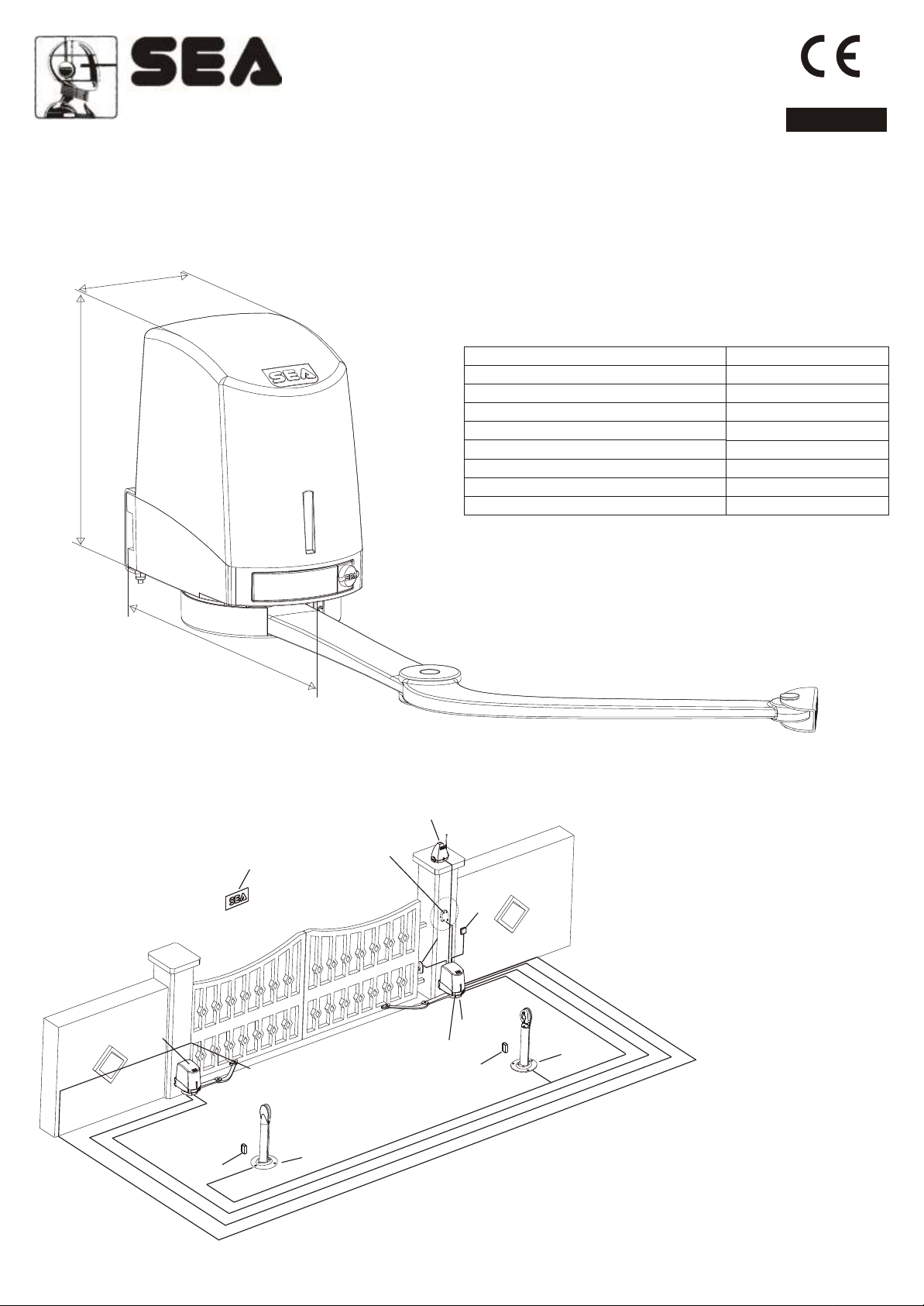
Flipper is an irreversible electromechanical swing gate operator for medium sized piers, maximum leaf length 2 m or 200Kg
weight (see drawing in Fig 4-A)
DIMENSIONS (mm)
166
FITTING AND CONNECTION INSTRUCTIONS
ENGLISH
266
Fig. 1
TECHNICAL DATA
Power Supply
Motor
Power
Working temperature
Weight
Max weight of the gate
Max. weight of the leaf
Opening degrees
482
FLIPPER
230 V (±5%) 50/60 Hz
24V
80 W
-20°C +55°C
8 Kg
200 Kg
2 m
110°
STANDARD INSTALLATION
1
2x 5
2,
5x1
3
13 x
5
8
01
G 8+ 5
2 , x1 5 1 x R
2x1
7
x3 1
6
1,53x
1-Operator 1
2-Operator 2
3-Stop in opening (where
possible)
4-Electronic unit included
4
2
6
3
9
3x1
5-Flashing lamp +
antenna
6-Photocell Ghost 40
7-Differential switch 16a-
0,03a
8-Key switch Key Plus
9
Fig. 2
21x
9-Column for photocell
Pilar + Ghost40
10-Warning plate
16
REV 02 - 03/2009
Sistemi Elettronici
di Apertura Porte e Cancelli
International registered trademark n. 804888
1
®
FLIPPER
FITTING AND CONNECTION INSTRUCTIONS
ENGLISH
2
3
4
7
8
5
6
10
9
Fig. 3
REV 02 - 03/2009
11
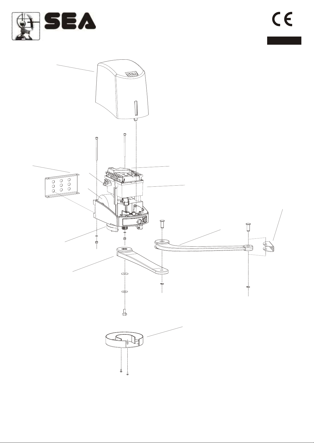
1. Carter
2. Anchrage plate
3. Fuse
4. Transformator
5. Electronic control unit
6. Battery/card support (battery optional)
7. Mech./electr. Stop (electronical optional)
8. Streight articulated arm
9. Curved articulated arm
10. Back fixation
11. Portection cover
17

®
FLIPPER
Sistemi Elettronici
di Apertura Porte e Cancelli
International registered trademark n. 804888
CARTER OFF MOUNTING
Open the little release door and take off the screw on the inside (Fig 4).
FITTING AND CONNECTION INSTRUCTIONS
ENGLISH
Fig. 4
FLIPPER WITH CONTROL UNIT
Fig. 5
FLIPPER WITHOUT CONTROL UNIT
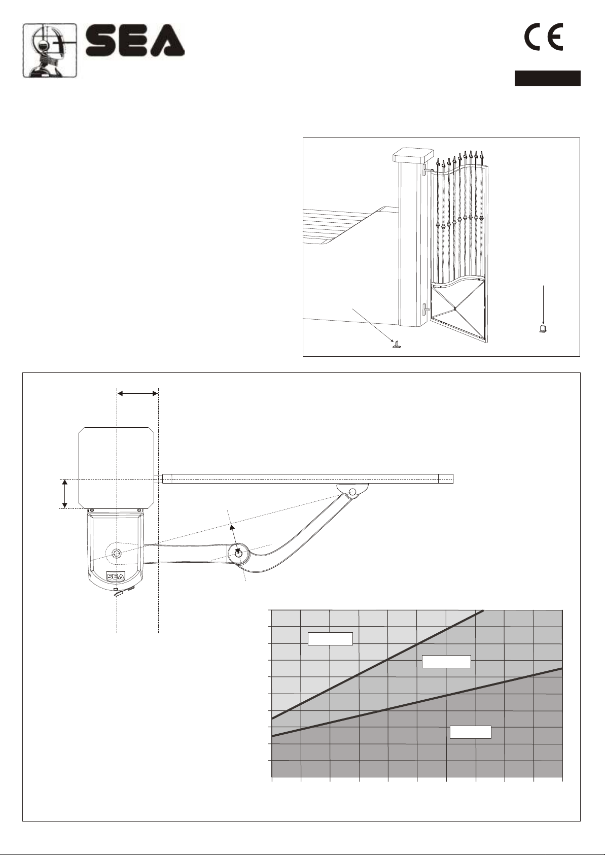
DRAWING LEAVES DIMENSIONS Fig. 4-A
200 Kg
180 Kg
160 Kg
•
USING
FIELD
140 Kg
CONNECTOR
120 Kg
0 Kg
1 mt
18 REV 02 - 03/2009
1,25 mt
1,5 mt
1,75 mt
•
2 mt
Limit switch
Common
Limit switch
opening
closing
Fig. 6
Stop
Motor
Motor
Fig. 6-A
®
FLIPPER
Sistemi Elettronici
di Apertura Porte e Cancelli
International registered trademark n. 804888
GA TE ARRANGEMENT
It is necessary to make controls on the gate to make sure the application of FLIPPER automation can be possible.
FITTING AND CONNECTION INSTRUCTIONS
ENGLISH
Make sure that:
A. The gate fixed and moving parts have a strong and crushproof structure;;
B. The weight of each leaf is not over 200 Kg (see drawing
pag. 18, Fig 4-A);
C. The length of each leaf is not over 2 m (see drawing pag.
18, Fig 4-A);
D. The hinges are strongly anchored and are able to support
the torque of the operator; they do not have irregular
movements and/or any friction during the whole movement of
the leaf;
The FLIPPER operator comes with limit switch stop in opening
and closing, nevertheless it is recommended to install
mechanical limit switch stops to be fixed on the ground in
DIMENSIONS FOR THE INSTALLATION
B
Fig. 7
Limit Switch stop
in closing
Limit Switch stop
in opening
Fig. 8
MAX 250 mm
A
C 1 /12 mm 00 0
300300
280280
260260
240240
220220
BB
200200
180180
160160
140140
120120
100100
105°/110°105°/110°
100°/105°100°/105°
90°/100°90°/100°
00 2525 5050 7575 100100 125125 150150 175175 200200 225225 250250
AA
REV 02 - 03/2009
19
 Loading...