

SEA FIELD Installation Manuals And Safety Information
International registered trademark n. 2.777.971
FIELD
INSTALLATION MANUALS
AND SAFETY INFORMATION
SEA USA Inc.
10850 N.W. 21st unit 160 DORAL MIAMI
Florida (FL) 33172
Phone:++1-305.594.1151 Fax: ++1-305.594.7325
Toll Free: 800.689.4716
web site: www.sea-usa.com
e-mail: sales@sea-usa.com
Rev.04 - 02/2016 67410825

FIELD
International registered trademark n. 2.777.971
Details
General
An appliance shall be provided with an instruction manual. The instruction manual shall give instructions for the installation,
operation, and user maintenance of the appliance.
The installation instructions shall specify the need for a grounding-type receptacle for connection to the supply and shall stress the
importance of proper grounding.
The installation instructions shall inform the installer that permanent wiring is to be employed as required by local codes, and
instructions for conversion to permanent wiring shall be supplied.
Information shall be supplied with a gate operator for:
a) The required installation and adjustment of all devices and systems to effect the primary and secondary protection against
entrapment (where included with the operator).
b) The intended connections for all devices and systems to effect the primary and secondary protection against entrapment. The
information shall be supplied in the instruction manual, wiring diagrams, separate instructions, or the equivalent.
Vehicular gate operators (or systems)
A vehicular gate operator shall be provided with the information in the instruction manual that defines the different vehicular gate
operator Class categories and give examples of each usage. The manual shall also indicate the use for which the particular unit is
intended as defined in Glossary, Section 3. The installation instructions for vehicular gate operators shall include information on
the Types of gate for which the gate operator is intended.
A gate operator shall be provided with the specific instructions describing all user adjustments required for proper operation of the
gate. Detailed instructions shall be provided regarding user adjustment of any clutch or pressure relief adjustments provided. The
instructions shall also indicate the need for periodic checking and adjustment by a qualified technician of the control mechanism
for force, speed, and sensitivity.
Instructions for the installation, adjustment, and wiring of external controls and devices serving as required protection against
entrapment shall be provided with the operator when such controls are shipped with the operator.
Instructions regarding intended installation of the gate operator shall be supplied as part of the installation instructions or as a
separate document. The following instructions or the equivalent shall be supplied where applicable:
a) Install the gate operator only when:
1) The operator is appropriate for the construction of the gate and the usage Class of the gate,
2) All openings of a horizontal slide gate are guarded or screened from the bottom of the gate to a minimum of 4 feet (1.22
m) above the ground to prevent a 2-1/4 inch (57.2 mm) diameter sphere from passing through the openings anywhere in
the gate, and in that portion of the adjacent fence that the gate covers in the open position,
3) All exposed pinch points are eliminated or guarded, and
4) Guarding is supplied for exposed rollers.
b) The operator is intended for installation only on gates used for vehicles. Pedestrians must be supplied with a separate access
opening. The pedestrian access opening shall be designed to promote pedestrian usage. Locate the gate such that persons will
not come in contact with the vehicular gate during the entire path of travel of the vehicular gate.
c) The gate must be installed in a location so that enough clearance is supplied between the gate and adjacent structures when
opening and closing to reduce the risk of entrapment. Swinging gates shall not open into public access areas.
d) The gate must be properly installed and work freely in both directions prior to the installation of the gate operator. Do not overtighten the operator clutch or pressure relief valve to compensate for a damaged gate.
e) (not applicable)
f) Controls intended for user activation must be located at least six feet (6’) away from any moving part of the gate and where the
user is prevented from reaching over, under, around or through the gate to operate the controls. Outdoor or easily accessible
controls shall have a security feature to prevent unauthorized use.
2
67410825
Rev.04 - 02/2016

FIELD
International registered trademark n. 2.777.971
g) The Stop and/or Reset button must be located in the line-of-sight of the gate. Activation of the reset control shall not cause the
operator to start.
h) A minimum of two (2) WARNING SIGNS shall be installed, one on each side of the gate where easily visible.
i) For gate operators utilizing a non-contact sensor:
1) See instructions on the placement of non-contact sensors for each Type of application,
2) Care shall be exercised to reduce the risk of nuisance tripping, such as when a vehicle, trips the sensor while the gate is
still moving, and
3) One or more non-contact sensors shall be located where the risk of entrapment or obstruction exists, such as the
perimeter reachable by a moving gate or barrier.
j) For a gate operator utilizing a contact sensor:
1) One or more contact sensors shall be located where the risk of entrapment or obstruction exists, such as at the leading
edge, trailing edge, and postmounted both inside and outside of a vehicular horizontal slide gate.
2) One or more contact sensors shall be located at the bottom edge of a vehicular vertical lift gate.
3) One or more contact sensors shall be located at the pinch point of a vehicular vertical pivot gate.
4) A hardwired contact sensor shall be located and its wiring arranged so that the communication between the sensor and
the gate operator is not subjected to mechanical damage.
5) A wireless contact sensor such as one that transmits radio frequency (RF) signals to the gate operator for entrapment
protection functions shall be located where the transmission of the signals are not obstructed or impeded by building
structures, natural landscaping or similar obstruction. A wireless contact sensor shall function under the intended enduse conditions.
6) One or more contact sensors shall be located on the inside and outside leading edge of a swing gate. Additionally, if the
bottom edge of a swing gate is greater than 6 inches (152 mm) above the ground at any point in its arc of travel, one or
more contact sensors shall be located on the bottom edge.
Revised 56.8.4 effective February 21, 2008
7) One or more contact sensors shall be located at the bottom edge of a vertical barrier (arm).
Instruction regarding intended operation of the gate operator shall be provided as part of the user instructions or as a separate
document. The following instructions or the equivalent shall be provided:
IMPORTANT SAFETY INSTRUCTIONS
WARNING – To reduce the risk of injury or death:
1. READ AND FOLLOW ALL INSTRUCTIONS.
2. Never let children operate or play with gate controls. Keep the remote control away from children.
3. Always keep people and objects away from the gate. NO ONE SHOULD CROSS THE PATH OF THE MOVING GATE.
4. Test the gate operator monthly. The gate MUST reverse on contact with a rigid object or stop when an object activates the noncontact sensors. After adjusting the force or the limit of travel, retest the gate operator. Failure to adjust and retest the gate
operator properly can increase the risk of injury or death.
5. Use the emergency release only when the gate is not moving.
6. KEEP GATES PROPERLY MAINTAINED. Read the owner’s manual. Have a qualified service person make repairs to gate
hardware.
7. The entrance is for vehicles only. Pedestrians must use separate entrance.
8. SAVE THESE INSTRUCTIONS.
67410825
Rev.04 - 02/2016
3

FIELD
International registered trademark n. 2.777.971
Changes Coming to UL 325 for Gate Operators
Starting on Jan. 12, 2016, new UL 325 changes take effect, bringing a series of new mandates for the
gate operator industry. Here’s a quick guide to the key modifications.
Entrapment-Protection Devices. Gate operators are required to have a minimum of two
1.
independent means of entrapment protection where the risk of entrapment or obstruction exists. A
manufacturer can use two inherent-type systems, two external-type systems, or an inherent and an
external system to meet the requirement. However, the same type of device cannot be used for both
means of protection.
2.
Monitoring Required. An external non-contact sensor or contact sensor may be used as a means of
entrapment protection. However, the sensor must be monitored once every cycle for (1) the correct
connection to the operator and (2) the correct operation of the sensor.
If the device is not present, not functioning, or is shorted, then the gate operator can only be operated
by constant pressure on the control device. Portable wireless controls will not function in this case.
3.
Entrapment Risk Identification. As in the past, it’s up to the installer to examine the installation and
determine where a risk of entrapment or obstruction exists. Manufacturers are required to provide
instructions for the placement of external devices, but they give only examples of suggested
entrapment protection in their installation manuals. If the installer identifies a risk of entrapment or
obstruction, at least two independent means of entrapment protection are required.
Terminology Change. The terms “primary” and “secondary” have been removed in the description of
4.
entrapment protection devices. This was done to emphasize that all entrapment protection devices
are equally important.
5.
The End of Type E. Type E (audible alarm) devices can no longer be used for entrapment protection.
This change was made because the Type E device is really a warning device, not an entrapmentprotection device. Also, all gate operator classes are now required to have an audio alarm that sounds
when two successive obstructions are encountered via a contact-type system.
Access Control Location for Emergency Use. An exception has been added in the manufacturer’s
6.
instructional requirements for the location of controls that operate the gate.
The instructional requirements state that these controls must be at least 6' away from any moving part
of the gate. In the new exception, “Emergency access controls only accessible by authorized
personnel (e.g., fire, police, EMS) may be placed at any location in the line-of-sight of the gate.”
Barrier-Arm Operator Exception. An exception has changed for barrier-arm gate operators
7.
requiring entrapment protection. The previous exception stated that a barrier-arm operator did not
require entrapment protection if the arm did not move toward a rigid object closer than 2'. The distance
has been reduced to 16" so it more closely aligns with the industry-defined entrapment protection
provisions in ASTM F2200.
Gate Operator Class II and Class III Definitions. The definitions for installation classes for gate
8.
operators were modified. Class II now includes commercial locations accessible to the general public.
Class III was refined to specify industrial locations not accessible to the general public. These
changes, while seemingly minor, may affect which gate operator is suitable for a particular installation
location.
4
67410825 Rev.04 - 02/2016
International registered trademark n. 2.777.971
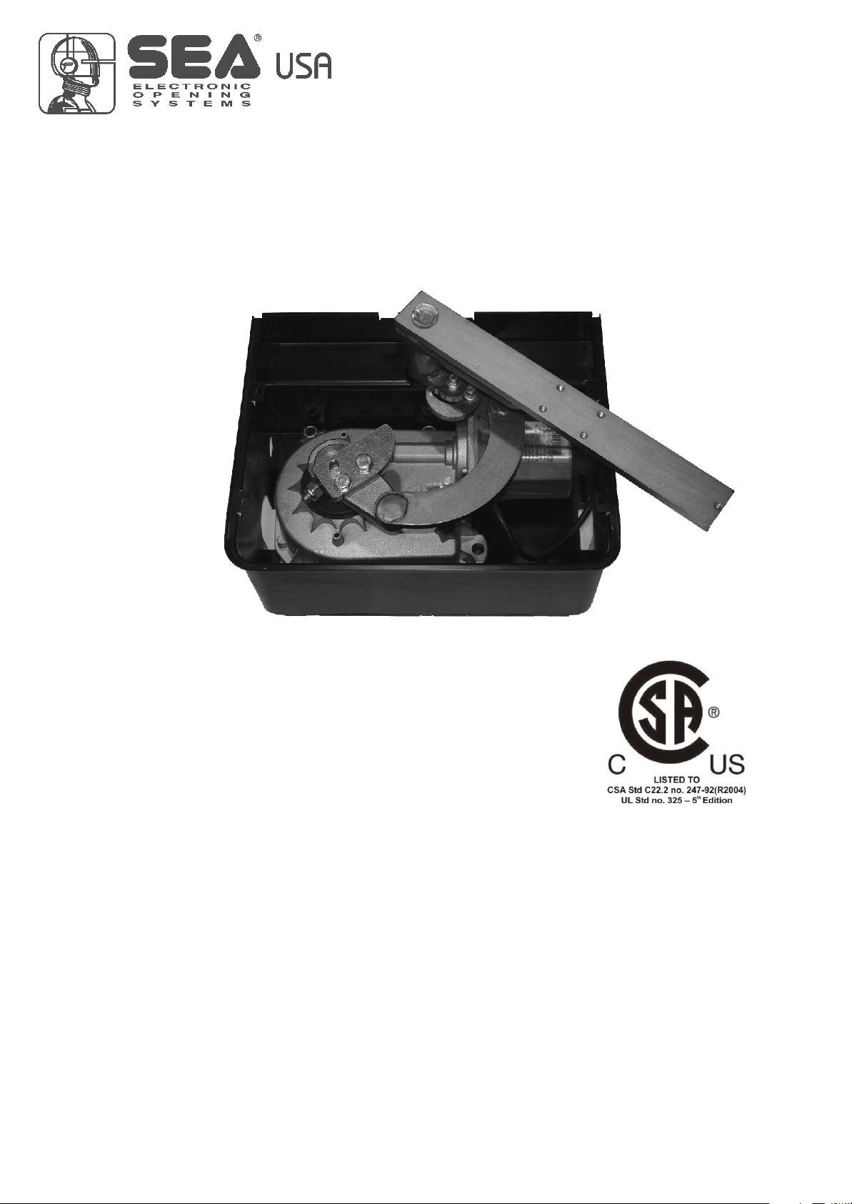
FIELD
MECHANICAL INSTALLATION
FIELD is an high quality electromechanical in-ground operator
for residential use for swing gates with a leaf lenght of 137,8
inches and weight leaf of 1322,8
Lbs.
Lubrication with grease (oil bath optional)
Available in 3 versions: slow, fast and also with low voltage
(24V) for maximum safety and intensive use.
Electronic limit switch and mecanichal stop in the carrying box.
Adjustable slow down in opening and closing with GATE
control Board.
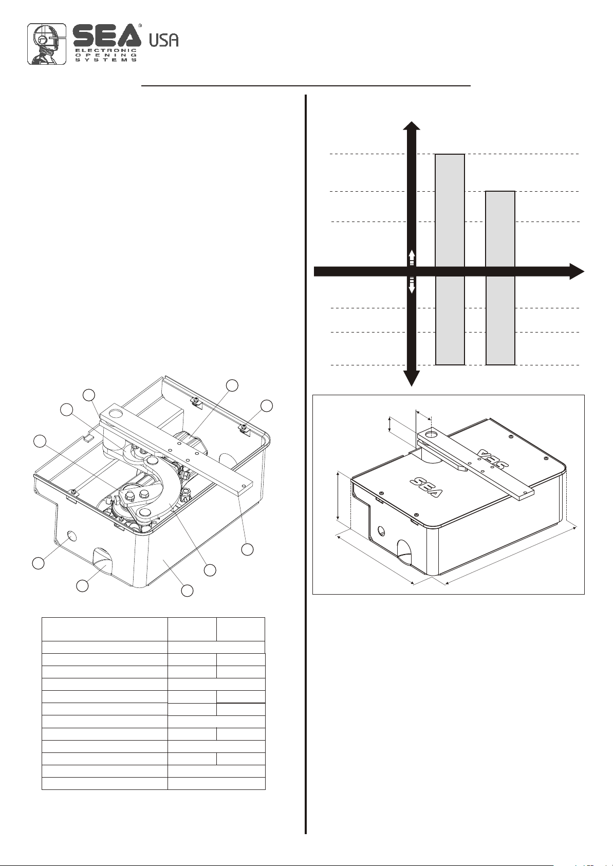
MAIN PARTS NOMENCLATURE
1 Handle bar device
2 Electric motor
3 Cover fixation screw
4 Leaf device
5 Counter-connecting rod
11
1010
99
6 Foundation carrying box
7 Hole for water discharge
8 Hole electric cable exit
9 Adjustable limit switch in closing
10 Adjustable limit switch in opening
22
33
GRAPHIC FOR THE USE OF
137,8 inches
118,1 inches
78,7 inches
661,4 Lbs
992,1 Lbs
1322,8 Lbs
2,5
FIELD AND FIELD 24V
FIELD OIL
FIELD OIL
Max leaf weight Max leaf lenght
1,8
DIMENSIONS (inches)
FIELD OIL 24V
FIELD OIL 24V
88
77
TECHNICAL DATA
Power supply
Absorbed Power
Frequency of use
Operating temperature
Weight
Max leaf width
Opening degree
Time of 90° movement
Protection class
Starting capacitor
Max torque
Max leaf weight
55
66
FIELD
OIL
120V (60 Hz)
280W
20 cycles/h
From -4°F to 131°F
27,5 Lbs
137,8 inc.
110° - 180° (optional)
18 s.
35 uF
1322,8 Lbs
FIELD
OIL 24V
130W
50 cycles/h
28,7 Lbs
118,1 inc.
14/30 s.
3R Type
-
300 Nm
6,9
44
Fig. 2
Fig. 1
1
2,7
16
1
,
1. GATE ARRANGEMENT
You must do some checks on the gate to see if fitting a FIELD
system is possible:
A. (Make sure that) the fixed and moving parts of the gate are
strong and non-deformable;
B. the weight of each gate leaf must not exceed 1322,8 Lbs
(Field Oil/Field Oil 24V) ;
C. the hinges and general structure must be in good condition
and the gate must move smoothly throughout its travel;
D. the upper hinge alone is sufficient to install the unit; those
which are unnecessary can be eliminated (the lower and that
in the middle if exists);
E. in case of leaf length superior of 70,9 inches and 330,7Lbs
of weight, it is recommended to fix to the ground a mechanical
stop in closing (Fig. 3).
67410825
Rev.04 - 02/2016
5
 Loading...