

SEA COMPACT 400,COMPACT 800 Fitting & User Instructions

Sistemi elettronici
di Aperture Porte e Cancelli
FITTING AND CONNECTION INSTRUCTIONS
ENGLISH
The Compact 400/800 consists of a hydraulic pump and a
hydraulic jack, both of which coupled in a supporting box
treated with cataphoresis.
The pump unit casing, which is used as an oil tank, contains the
electric motor, fluid pump, distributor and hydraulic oil.
It is also provided with an adjustable slowing-down device in
the two stop phases of the leaf .
The wheeling unit is composed by a double piston connected to
a rack which engages with the pinion of the leaf dragging shaft.
Gates up to 2 meters long can be securely locked using the
operators internal hydraulic locking system, thus ensuring
perfect keeping in closing and in opening.
For gate in excess of stated value: A hydraulic non locking
operator should be used in conjunction with a separate electrical
locking device to ensure keeping in closing.
For rotation angles not included between 90°-100 and 130°140° respectively, slowing down is either in closing or in
opening.
In case of power failure: The operator's internal hydraulic locking
can be released using a special key and the gate used manually.
(versions with slow-down only)
1 Release Cover
2 Release Extention
3 Braking regulation screw
(where provided)
4 Exit hole for electric cables
5 By-pass regulation
Compact 400 Compact 800
230 V (±5%) 50/60 Hz
220 W
1,1 A
1400 rpm
45
50 bar
40 bar
-20°C +55°C
130°C
56 da Nm
12,5uF
13 Kg 13,8 Kg
IP55
400 Kg 800 Kg
Versions with slow-down
REV 02 - 09/2005
6 Filling oil Cap
7 Oil level indicator
8 Water draining hole
9 Draining screw
10 Screw for braking regulation stop
MAIN PARTS NOMENCLATURE
1. GATE ARRANGEMENT
You must do some checks on the gate to see if fitting a
COMPACT system is possible:
A. (Make sure that) the fixed and moving parts of the gate are
strong and non-deformable;
B. the weight of each gate leaf must not exceed 400 Kg
(Compact 400), 800 Kg (Compact 800) ;
C. the hinges and general structure must be in good condition
and the gate must move smoothly throughout its travel;
E. as the limit switches are not provided within the actuator, it is
necessary to install mechanical limit switches stops to be fixed to
the ground in closing and in opening (Fig. 3).
D. the upper hinge alone is sufficient to install the unit; those
which are unnecessary can be eliminated (the lower and that in
the middle if exists);
DIMENSIONS (mm)
cod. 67410085
TECHNICAL DATA
Power supply
Motor Power
Absorbed current
Motor rotation speed
Cycles hour (with a 20°C temperature)
Max Pressure of the 0.50 lt pump in use
Max Pressure of the 0,75 lt pump in use
Operating temperature
Thermal protection intervention
Max torque
Starting capacitor
Weight
Protection class
Maximum weight of the gate
Braking regulation
11
22
33
44
55
66
77
88
99
1010
33
218
209
50
395
- 4
0
*
4
2 meters
COMPACT
400
AC
4 meters
800 Kg
400 Kg
Max leaf weight Max leaf width
Underground hydraulic operators
GRAPHIC FOR THE USE OF COMPACT 400
AND COMPACT 800 OPERATORS
COMPACT
400
AC
COMPACT 400 SB
(With electric lock)
COMPACT
400
SB (w.e.l.)
COMPACT
800 AC
COMPACT 800
AC
COMPACT 800 SB
(With electric lock)
COMPACT 800
SB
(With electric lock)
Fig. 1
* 180° version
Fig. 2
13/32
COMPACT 400 (with and without slowdown)
COMPACT 800 (with and without slowdown)
Sistemi elettronici
di Aperture Porte e Cancelli
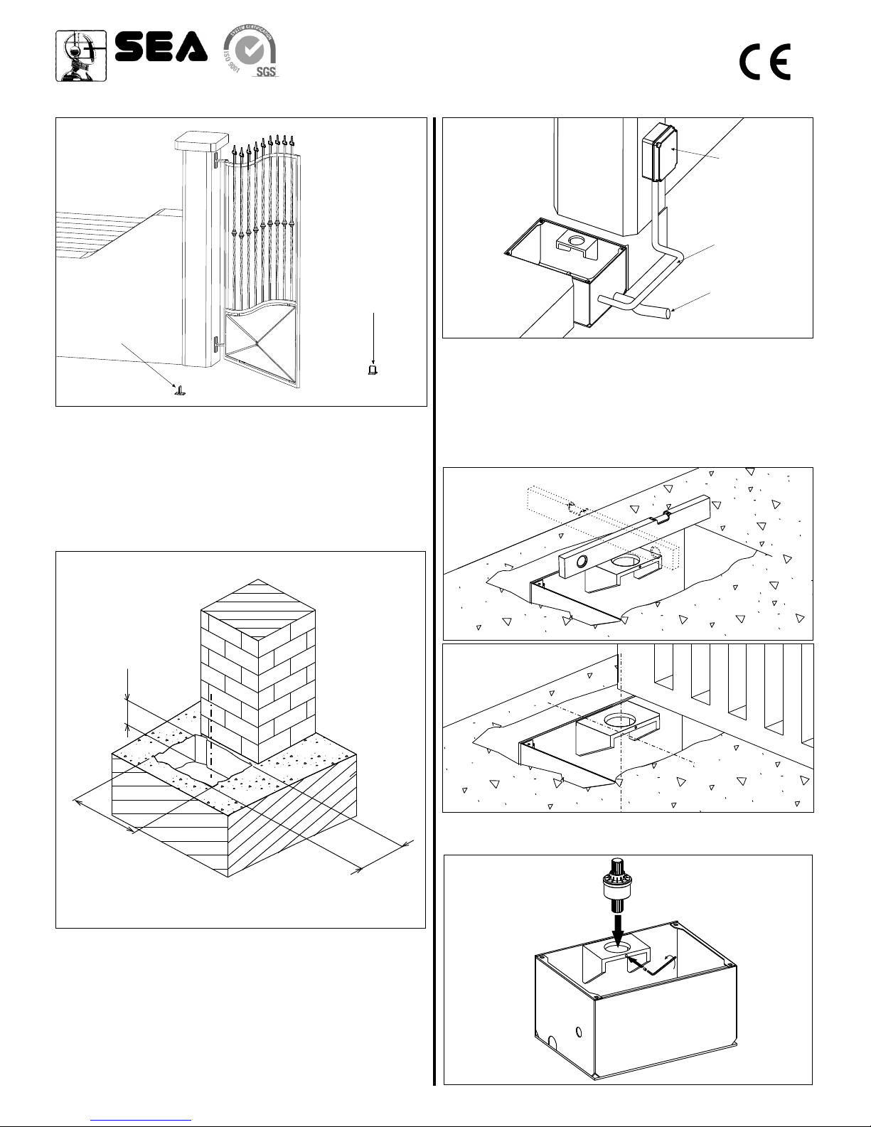
Fig. 7
2.2. Inside the excavated pit you have to plan:
- rain water drainage;
- a water waste pipe in flexible plastic of about 40 mm of
diameter to put inside the provided hole of the box before it is
concreted (Fig. 5). It must be brought until the drain of the
sewer line;
- a sheath for the passage of electrical cables of about 20 mm
of diameter which must be brought to the proximity of the
electric connection box (Fig. 5).
Fig. 6
2. CARRYING BOX INSTALLATION
2.1. The hole which contains the carrying box must have the
approximate dimensions mentioned in Fig. 4.
For a correct placing, it is obbligatory to follow closely the quote
of 60 mm which corresponds to the minimum distance of the
rotation axis from the pillar.
Fig. 4
60
0 -
6
40*
450
220
* Compact 400 180°/Compact 800 180° box versions
dimensions (mm)
Fig. 3
Limit switch stop
in opening
Limit switch stop
in closing
2.3. Before concreting the carrying box, use a level to make it
perfectly horizontal to the ground (Fig. 6) and perpendicular to
the axis of the gate (Fig. 7).
The axis of the upper hinge of the gate must correspond exactly
to the axis of the carrying box shaft.
Follow the distance of 50 mm closely between the carrying box
cover and the base of the gate (Fig. 2) remembering that the Ushaped iron will be inserted on it (see the paragraph 3).
Fig. 5
Sheath for electric
cables passage
Flexible pipe
for water draining
Electric
connection box
2.4. Put the jointed splined shaft into the upper hole of the
carrying box and fix it with the provided screw (Fig. 8)
Fig. 8
REV 02 - 09/2005cod. 67410085
14/32
 Loading...