

SEA 7157 Operator's Manual
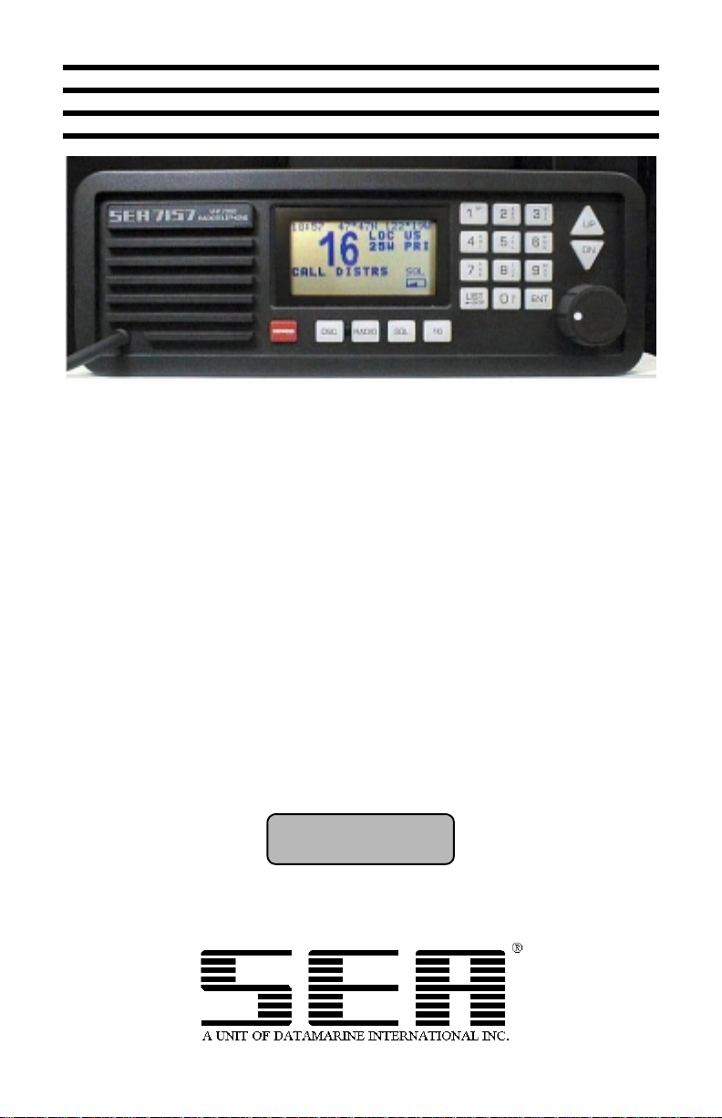
SEA 7157 OPERATOR’S MANUAL
25W VHF/DSC RADIOTELEPHONE
Software Version:
Ver. 1.10 11, Feb 1999


TABLE OF CONTENTS
GENERAL OPERATIONS...............................................................................1
Technical Specifications...................................................................................1
General Information .........................................................................................2
LCD Display Characters...................................................................................3
Front Panel Controls.........................................................................................3
Basic Operation................................................................................................4
Turning The Radio ON.....................................................................................5
Selecting A Channel List..................................................................................5
Selecting A Channel.........................................................................................6
Adjusting The Squelch.....................................................................................6
Channel 16 Key................................................................................................7
Operating The Transmitter ...............................................................................7
ADVANCED RADIO OPERATIONS..............................................................8
Selecting The Radio Menu...............................................................................8
Changing The Transmit Power Level...............................................................8
LCD Contrast Adjustment................................................................................9
Dimming The Backlighting..............................................................................9
Receiver Sensitivity..........................................................................................9
Changing The Priority Channel........................................................................9
Assigning MEM Channels For Scanning........................................................10
Dual Watch Scan............................................................................................10
Search Scan ....................................................................................................11
Memory Scan..................................................................................................11
Scan Options...................................................................................................12
Reviewing Memory Channels.........................................................................12
Adjusting The Scan Hang Time......................................................................13
Clearing The Radio Memory..........................................................................13
Changing The Beep........................................................................................13
Naming A Channel.........................................................................................14
Checking The Software Version.....................................................................14
DSC OPERATIONS.........................................................................................15
DSC Distress Calling......................................................................................15
Selecting The DSC Menu...............................................................................16
Routine Individual DSC Calls........................................................................17
DSC Calls Using Alternate Calling Channel..................................................17
DSC Distress Relay Calls...............................................................................18
All Ships DSC Calls.......................................................................................18
Placing A Telephone Call With DSC.............................................................19
Receiving A DSC Call....................................................................................19
Reviewing The DSC Call Logs.......................................................................20

TABLE OF CONTENTS
GMDSS CLASS A CALLS..............................................................................21
Details Of A “Class A” Call...........................................................................21
Distress Call....................................................................................................24
All Ships Calls................................................................................................25
Geographical Area Calls.................................................................................26
Individual / Group Calls.................................................................................27
Phone Calls.....................................................................................................28
PROGRAMMING DSC OPTIONS................................................................29
DSC Programming..........................................................................................29
Setting The Date & Time................................................................................29
Programming The DSC ID (MMSI)...............................................................30
Programming The Navigation Interface .........................................................30
Programming Options.....................................................................................31
Using Test And Diagnostic Utilities...............................................................32
Programming The DSC Directory..................................................................32
Programming The Telephone Directory.........................................................33
Inputting Position Data...................................................................................34
FREQUENCY LISTINGS...............................................................................35
USA Channel List...........................................................................................35
Amended International List............................................................................36
International Channel List ..............................................................................37
Weather Channel List.....................................................................................38
REAR PANEL..................................................................................................39
Rear Panel Connections..................................................................................39
GLOSSARY......................................................................................................41


GENERAL OPERATIONS
TECHNICAL SPECIFICATIONS
DIMENSIONS
3.9” H x 10.5” W x 10.9” D
99mm H x 265mm W x 278mm D
WEIGHT
7.75 Lbs.
3.5 Kgs.
ELECTRICAL
Type Acceptance FCC Parts 80, 15
FCC Identifier BZ6SEA7157
Frequency Range (TX) 155 - 159 MHz
Operating Temperature -30 degrees to +60 degrees C
Frequency Stability
Emission 16K0G3E, 13K5G2B
Primary Voltage 12 or 24 VDC +30%, -10%
Current Drain 12 Volts Receive Standby 0.5 Amp
Output Impedance 50 ohms
Transmitter Output Power 25W, 1W
Frequency Deviation 5 KHz maximum peak
Receiver Sensitivity
Audio Output
Channel 70 Receiver Sensitivity
DSC Facility
:
:
:
GMDSS (Para 80.1101)
EIA RS-204C, RS-152B
(RX) 155 - 163.6 MHz
±
5 ppm
Floating Chassis
Receive Full Audio 1.0 Amps
Max TX: (25W) 4.5 Amps
(1W) 1.0 Amp
24 Volts Receive Standby 0.3 Amp
Receive Full Audio 0.5 Amps
Max TX: (25W) 2.35 Amps
(1W) 0.80 Amp
≤
0.3 µV for 12 dB SINAD
4 W @ ≤ 10% distortion into external
4 ohm load. 2 W internal
≤
1 µV for 20 dB SINAD
≤
1 µV for 10
-2
B.E.R.
1

GENERAL OPERATIONS
GENERAL INFORMATION
CAUTION
Do not attempt to transmit until the radiotelephone has warmed up for at least 30
seconds. Transmitting before the 30 second warm up period may cause a
violation of the Fe deral Communications Commission regulations.
!
PROPAGATION
Very High Frequencies (VHF) in the range of 30 MHz to 300 MHz may travel
far beyond the horizon under ideal conditions. For reliable communications,
VHF transmissions should be limited to no more than 30 miles.
INSTALLATION (RF grounding & DC connections)
The SEA 7157 may be configured to operate from either 12 or 24 volts DC
(direct current). Check the rear panel of the radio to determine the proper
operating voltage required. A direct connection to the power source is
recommended. Proper wire size must be used between the radio and power
source to prevent the DC voltage at the radio from dropping below 10.8 or 21.6
volts during transmit conditions. Should this occur, the radio may produce
distorted transmissions. Connect the RED positive (+) lead from the radio to the
positive supply terminal. The BLACK negative (-) power lead should connect to
the negative supply terminal. A #10 ground stud is provided for connecting the
radio chassis to the ship’s earth connection with a copper strap.
The SEA 7157 is equipped with two UHF type RF connectors for the
installation of two independent antennas. One antenna allows constant
monitoring of the DSC channel while the other antenna labeled “ANTENNA 50
OHMS” is used for normal radio operations. The nominal impedance of each
antenna is 50Ω which requires high quality RG-213/U or equivalent coax.
It is recommended that an authorized SEA dealer perform the installation of your
VHF equipment to assure proper operation. For complete installation
instructions, refer to the “SEA 7157 Installation Manual” (OPR-7157-INST)
supplied with the radio.
RADIO PROTECTION
The chassis of the SEA 7157 is not connected to either supply rail. This allows a
direct connection to the ship’s earth connection for voltage and RF interference
protection. In the event that the input voltage is reversed, the line fuse (7.5 amp
for 12 volt operation or 5 amp for 24 volt operation) will blow. It is also likely
that the internal reverse polarity protection diode CR20 will be damaged in order
to protect the remaining circuitry. Overvoltage to the radio will cause similar
results. If this should occur and a replacement fuse also blows, an authorized
SEA dealer should be contacted for proper service repairs.
2
GENERAL OPERATIONS
LCD DISPLAY CHARACTERS
TX
25W
1W
DX
LOC
PRI
SQL
US
INT
WX
A
16
0 – 9
DISTRESS
The radio is in TRANSMIT.
Indicates the radio will transmit using 25 watts of output power.
Indicates the radio will transmit using 1 watt of output power.
The radio is set for maximum receive sensitivity.
The radio is set for local receive sensitivity.
Displayed channel is the priority channel.
Changes to bold font when adjusting the SQUELCH threshold.
Indicates US channel list is enabled.
Indicates International channel list is enabled.
Indicates Weather channel list is enabled.
Indicates the displayed channel is US simplex.
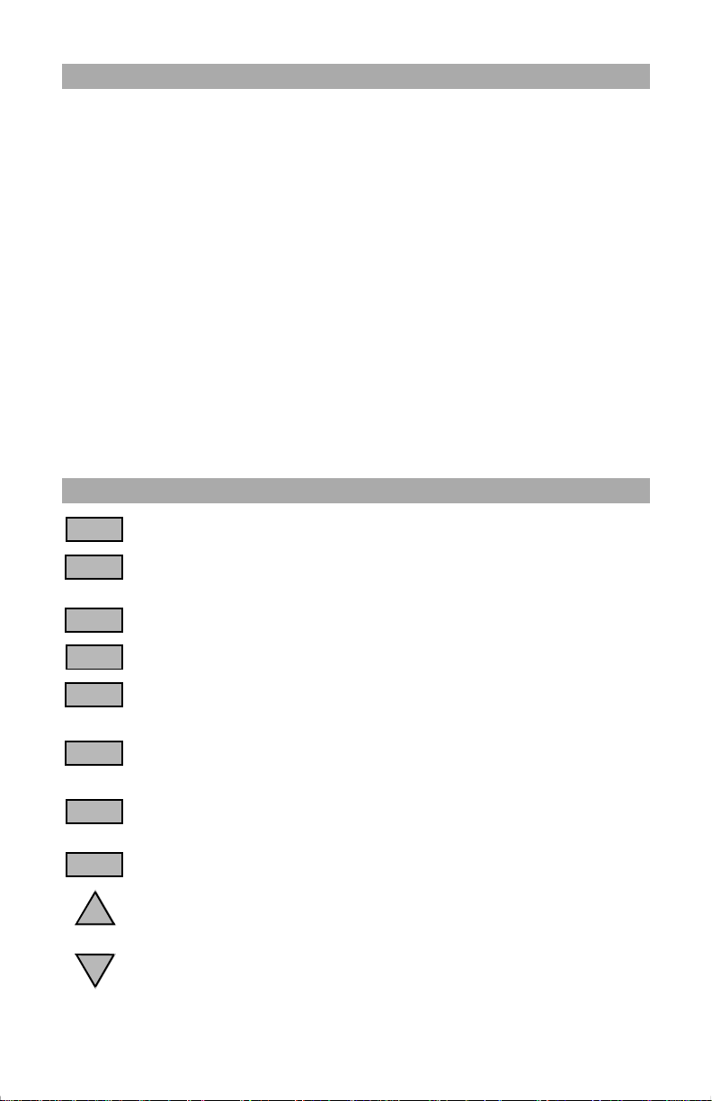
FRONT PANEL CONTROLS
Toggles channel selection between priority channel and CH 16.
Allows entry of channel selection, alphanumeric channel
information and menu selections.
Initiates an Emergency DSC call.
DSC
RADIO
SQL
LIST
←
BKSP
ENT
UP
DN
Selects DSC operations.
Toggles bet ween radio menu selections and normal operations.
Aborts DSC operations.
Allows quick access to squelch settings for normal operations.
Selects print feature in other modes.
Selects US, INT or WX channel list. Also serves as a backspace
key when used for alphanumeric entry or selects previous menu.
Selects displayed function or completes keyed entry .
Increases squelch, channel, alphanumeric and contrast settings.
Also scrolls through DSC memory logs.
Decreases squelch, channel, alphanumeric and contrast settings.
Also scrolls through DSC memory logs.
3
GENERAL OPERATIONS
A
VHF / DSC
SEA 7157
RADIOTELEPHONE
A UNIT OF DATAMARINE
Ver 1.10 11 FEB 1999
C. SEA Inc., 1999
DISTRESS
DSC
RADIO
SQL
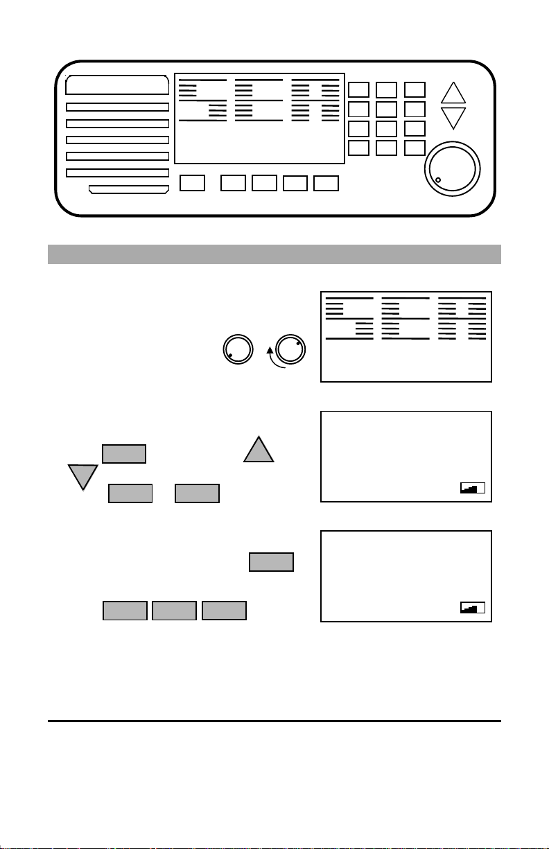
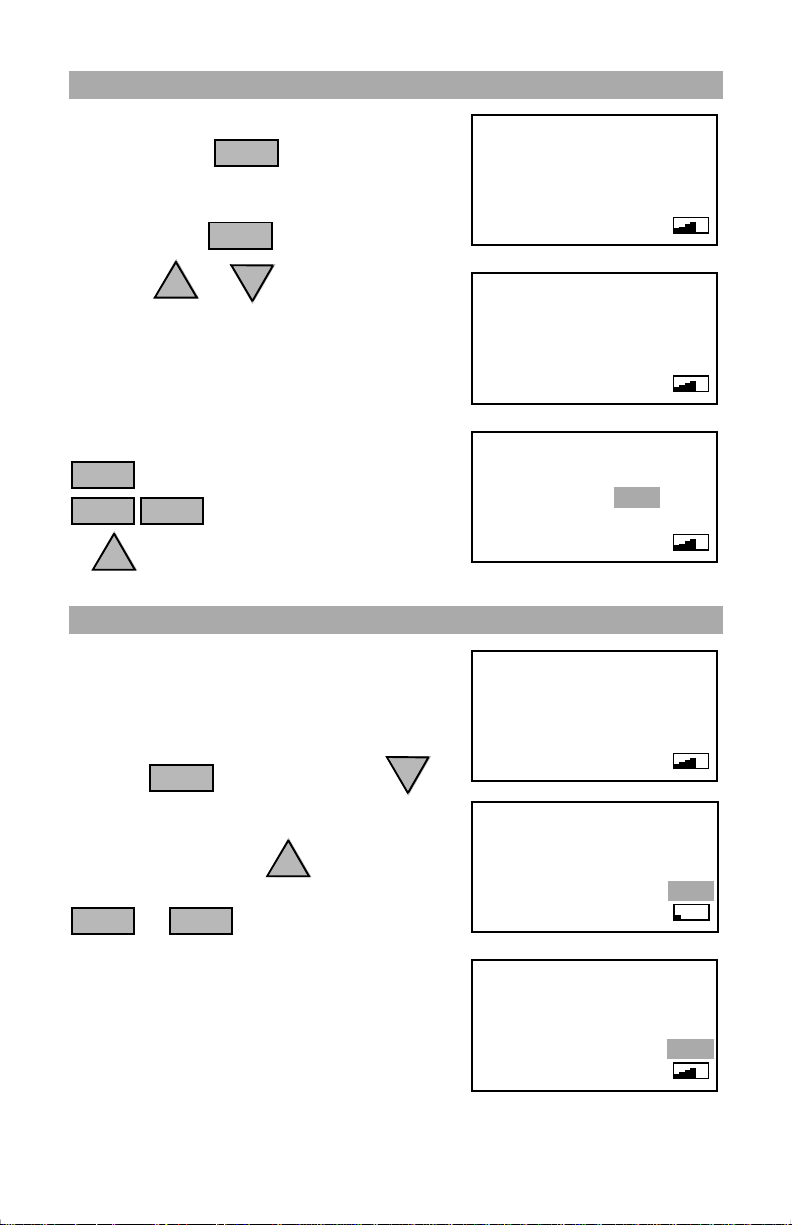
BASIC OPERATION
To turn the radio on, rotate the volume control
clockwise until a click is heard.
Rotating the volume control
clockwise after the click is
heard will increase the volume level.
Rotate the volume control fully counter
clockwise to turn the radio off.
DN
SQL
RADIO
ENT
Press the key followed by the
or key to adjust the squelch threshold.
Press the or key to stop
squelch adjustment.
UP
1
4
7
LIST
←
BKSP
SP
G
H
I
P
R
S
D
B
E
2
3
C
F
J
K
6
5
L
T
U
8
9
V
Q
ENT
Z
0
UP
M
N
O
DN
W
X
Y
16
A UNIT OF DATAMARINE
Ver 1.10 11 FEB 1999
C. SEA Inc., 1999
2:43 47° 47N 122° 19W
DX
25WUSPRI
16
PRESS UP/DOWN
TO ADJUST SQL
SQL
Enter the desired channel number in one, two
or three digit form, followed by the
ENT
key.
e.g.
2
A
B
C
6
M
N
ENT
O
2:43 47° 47N 122° 19W
DX
US
25W
26
PUBLIC CORR
SQL
Your SEA 7157 is now set to transmit and receive on the selected channel.
For instructions on using additional radio functions, see the table of contents for
the page number corresponding to the specific function.
Illustrations in this manual may differ from your own depending on enabled
programming features, selected channel list and differences in display fonts.
4
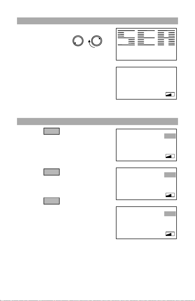
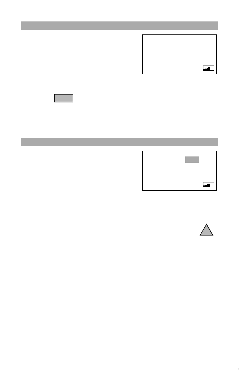
TURNING THE RADIO ON
Rotate the volume control clockwise until a
click is heard.
GENERAL OPERATIONS
A checkerboard display
will be shown for a short period followed by
the software version. The radio will be set to
the last selected channel and squelch setting
save d in memory.
Rotating the volume control clockwise beyond
the click will increase the volume level.
When the radio is turned off, all scan routines
are canceled. The current channel, channel list,
and squelch setting will be recalled the next
time power is applied.
SELECTING A CHANNEL LIST
Pressing the key will cycle the radio
through the three available channel li s ts.
The US channel list contains channel settings
unique to the United States. When selected,
the last used US channel will be recalled.
Pressing the key while in the US list
will cycle the radio to the
channel list. The last used INT channel will be
recalled.
LIST
←
BKSP
LIST
←
BKSP
(International)
INT
A UNIT OF DATAMARINE
Ver 1.10 11 FEB 1999
C. SEA Inc., 1999
Software version number and date
2:43 47° 47N 122° 19W
26
PUBLIC CORR
Last used channel is recalled at powerup
2:43 47° 47N 122° 19W
26
PUBLIC CORR
2:44 47° 47N 122° 19W
INTERSHIP
DX
25W
DX
25W
US channel list
DX
25W
6
US
SQL
US
SQL
INT
SQL
Pressing the key while in the INT list
will cycle the radio to the last WX (Weather)
channel used from the WX channel list. Ten
receive only
receiving current weather conditions in the
local area.
LIST
←
BKSP
weather channels are available for
5
International list
2:44 47° 47N 122° 19W
WEATHER
Weather channel list
1
DX WX
SQL
GENERAL OPERATIONS
A
SELECTING A CHANNEL
Select the channel list containing the required
channel with the key.
The channel may be selected by entering the
channel number directly with the number keys
followed by the key.
Using the and keys will allow the
next or previous channel in the list to be
accessed. When a simplex channel is needed,
enter the closest channel number next to the
desired channel and press the up or down key.
e.g. To select CH 1
LIST
←
BKSP
1
UP
UP
the following keys:
repeatedly until the US list appears.
SP
ENT
key to access CH 1
LIST
←
BKSP
ENT
DN
A
from the US list, press
for CH 1.
A
.
ADJUSTING THE SQUELCH
The squelch prevents unwanted noise from
getting through to the speaker. The highe r the
squelch setting, the less chance of noise getting
through.
Press the key followed by the
key until noise is heard through the speaker.
Increase the number of squelch bars on the
display by pressing the key until the
noise stops. This is the ideal setting
for the squelch threshold. Pressing either the
RADIO
adjustment.
In the event that noise occasionally opens the
squelch, incre ase the number of squelch bars on
the display by one or two .
Adjusting the squelch threshold too high may
cause desired signals to be missed.
SQL
UP
ENT
or key will stop squelch
DN
2:44 47° 47N 122° 19W
26
PUBLIC CORR
Select the proper channel list
2:44 47° 47N 122° 19W
2:44 47° 47N 122° 19W
PORT OPERS
Use the UP key to access US CH 1A
2:45 47° 47N 122° 19W
26
PUBLIC CORR
2:45 47° 47N 122° 19W
26
PRESS UP/DOWN
TO ADJUST SQL
Low squelch setting
2:46 47° 47N 122° 19W
26
PRESS UP/DOWN
TO ADJUST SQL
Ideal squelch setting
1
US CH 1
1
DX
25W
DX
25W
DX
25W
DX
25W
DX
25W
DX
25W
US
SQL
US
SQL
US
SQL
US
SQL
US
SQL
US
SQL
6
GENERAL OPERATIONS
CHANNEL 16 KEY
Channel 16 is used as a calling channel and as
an international emergency channel. Channel
16 should be monitored when the radio is not
being used for other communications.
Do not use this channel for ordinary communications.
Pressing the key will set the radio to full output power and abort all
other functions. Pressing the key a second time will switch the radio to the
programmed priority channel. When channel 16 is programmed to be the
priority channel (factory default), switching between channel 16 and the priority
channel will produce no noticeable change.
16
2:46 47° 47N 122° 19W
16
CALL DISTRS
Instant recall of CH 16 and Priority channel
DX
25WUSPRI
SQL
OPERATING THE TRANSMITTER
Keying the microphone push-to-talk button will
switch the transmitter circuits on, indicated by
the ‘TX’ indicator appearing on the display.
Speak in a normal voice with your lips about
one eighth of an inch away from the
microphone. Do not shout. Shouting reduces
intelligibility.
If regulations prohibit 25 watts of power on a given channel, the power level
cannot be changed. No power level selection is allowed on receive only
channels (e.g. WX channels).
US channels 13, 67, and 77 can be operated at full power by pressing the
key during transmission. Releasing the key will return the radio to 1 watt
operation.
2:46 47° 47N 122° 19W
26
PUBLIC CORR
Display showing transmit condition
TX
25W
US
SQL
UP
A time out timer is provided to prevent continuous transmissions for periods
greater than 5 minutes. In the event that the radio will be needed to transmit for
periods longer than 5 minutes, it will be necessary to release the PTT briefly
before the 5 minute timer expires.
7
ADVANCED RADIO OPERATIONS
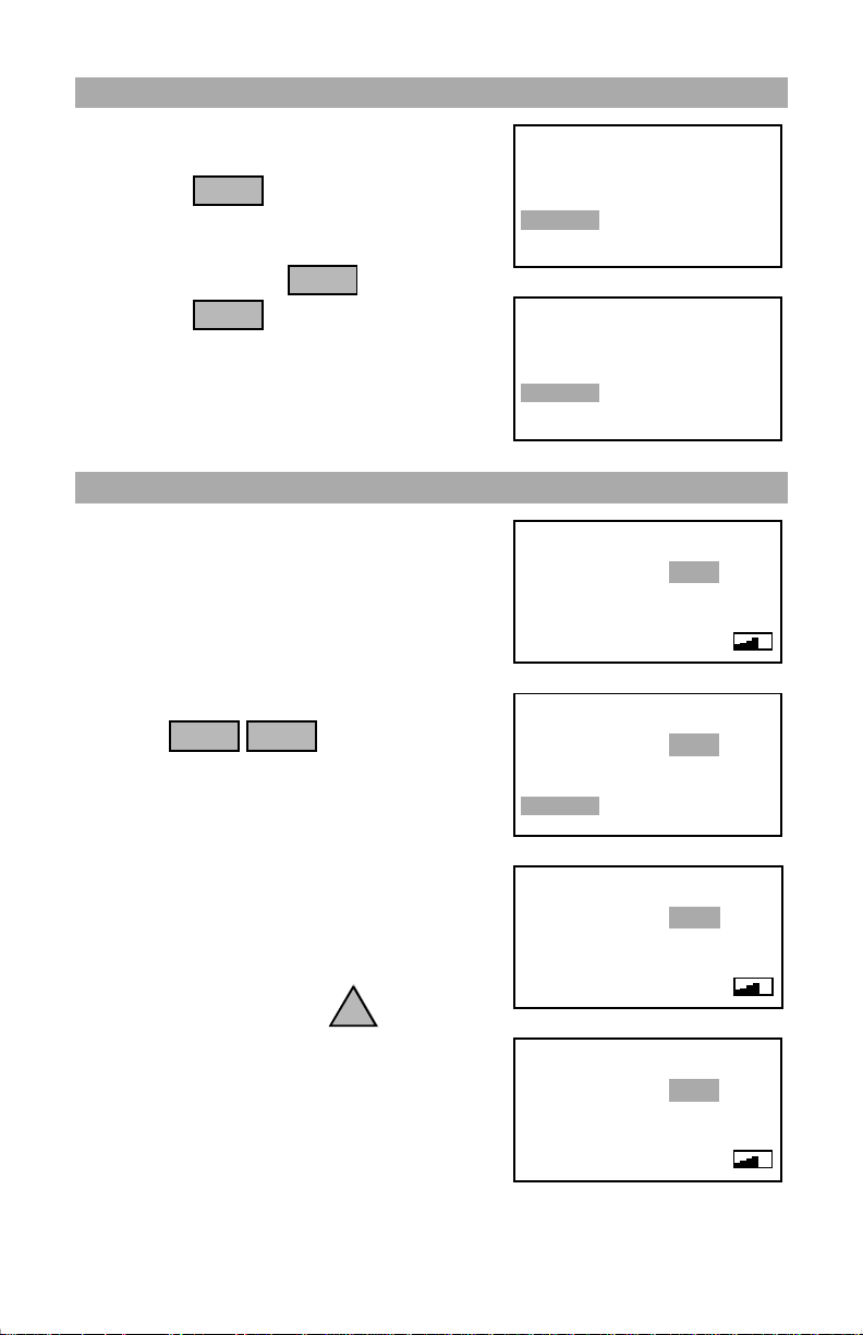
SELECTING THE RADIO MENU
Several advanced radio options are accessed by
pressing the key.
The most commonly used functions will be
displayed in the first menu. The second menu
is accessed by pressing .
Pressing the key at any time will
abort the menu selection and the radio will
return to normal operations.
RADIO
RADIO
1
SP
CHANGING THE TRANSMIT POWER LEVEL
The transmit power level may be changed
between 1 and 25 watts. The display will show
the current setting while the menu selection
shows what the power level will become.
e.g. To change b etween high (25W) and low
(1W) power levels:
G
RADIO
Press to toggle the power
level.
If regulations prohibit 25 watts of power on a
given channel, the power level cannot be
changed. No power level selection is allowed
on receive only channels (e.g. WX channels).
USA channels 13, 67, and 77 may be operated
at full power by pressing the key during
transmission. Releasing the key will
return the radio to 1 watt operation.
When communicating short distances, it is
recommended that the 1 watt level be used to
help prevent interference with other stations.
4
H
I
UP
2:47 47° 47N 122° 19W
16
1=MORE
4=1W
7=MEM
Primary Radio menu selections
2:47 47° 47N 122° 19W
16
1=PREV
4=RVW
7=BEEP
Secondary Radio menu selections
2:47 47° 47N 122° 19W
16
CALL DISTRS
Channel 16 at 25 watt power setting
2:47 47° 47N 122° 19W
16
1=MORE
4=1W
7=MEM
Changing CH 16 from 25W to 1W
2:47 47° 47N 122° 19W
16
CALL DISTRS
Channel 16 at 1 watt power setting
2:47 47° 47N 122° 19W
13
BRG TO BRG
Channel 13 at 25 watts while UP key is pressed
DX
25WUSPRI
2=DW 3=SRCH
5=DIM 6=LOC
8=SCAN 9=PRI
DX
25WUSPRI
2=SRMD 3=SCMD
5=CLR 6=HNG
8=NAME 9=VER
DX
25WUSPRI
SQL
DX
25WUSPRI
2=DW 3=SRCH
5=DIM 6=LOC
8=SCAN 9=PRI
DX
1WUSPRI
SQL
TX
US
25W
SQL
8

ADVANCED RADIO OPERATIONS
LCD CONTRAST ADJUSTMENT
The display’s contrast setting may need to be
adjusted to compensate for differences in
temperature and viewing angle.
To change the contrast level press
followed by or . The keys may be
held or pressed repeatedly.
Pressing will exit the contrast adjustment.
UP
RADIO
DN
RADIO
2:48 47° 47N 122° 19W
16
1=MORE
4=1W
7=MEM
Low contrast setting
DX
25WUSPRI
2=DW 3=SRCH
5=DIM 6=LOC
8=SCAN 9=PRI
DIMMING THE BACKLIGHTING
The display and keypad backlighting may be
changed by pressing t he keys.
Repeatedly pressing the
J
K
5
key will cycle the backlighting
L
RADIO
through the vario us l evels. Pressing
5
J
K
L
ENT
will exit backlighting adjustment.
If the backlighting is set to off, the first keypress will turn the backlighting on to
the lowest level for 5 seconds.
2:48 47° 47N 122° 19W
16
1=MORE
4=1W
7=MEM
Radio 5 changes backlighting
DX
25WUSPRI
2=DW 3=SRCH
5=DIM 6=LOC
8=SCAN 9=PRI
RECEIVER SENSITIVITY
The SEA 7157 receiver sensitivity may be
adjusted for local or distant signals. When
working in harbor, it is best to set the LOC/DX
sensitivity to LOC. A setting for LOC will
reduce the amount of interference caused from
pagers and other communications systems.
To select the receiver sensitivity, press .
RADIO
2:47 47° 47N 122° 19W
16
1=MORE
4=1W
7=MEM
DX / LOC receive sensitivity
M
N
6
O
DX
25WUSPRI
2=DW 3=SRCH
5=DIM
8=SCAN 9=PRI
6=LOC
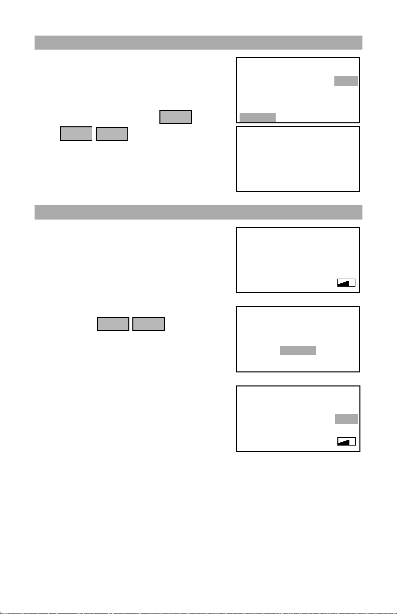
CHANGING THE PRIORITY CHANNEL
When it is necessary to Dual Scan (Watch) a
given frequency and the priority channel, it
may be necessary to program the priority
channel to something other than channel 16.
To change the priority channel, select the
channel that will become the priority channel
and press . Press to make the displayed channel the
ENT
RADIO
9
W
X
Y
priority channel.
2:48 47° 47N 122° 19W
13
1=MORE
4=1W
7=MEM
Setting CH 13 to be the priority channel
DX1WUS
PRI
2=DW 3=SRCH
5=DIM 6=LOC
8=SCAN
9=PRI
9
ADVANCED RADIO OPERATIONS
ASSIGNING MEM CHANNELS FOR SCANNING
Channels may b e marked for memory scan
operation. Memory scan will scan only those
channels that are marked as ‘MEM’.
To assign a channel as a MEM channel,
select the channel followed by .
P
RADIO
Press to select or deselec t the
channel as a memory channel.
Memory channels may not be available
depending on code version and regulations.
7
R
S
ENT
DUAL WATCH SCAN
Dual Watch scanning (DW) allows you to scan
between the selected and priority channel. The
channel being received will be displayed in
large numbers while the second channel being
watched will simultaneously be displayed in
small numbers above the ‘SQL’ annunciator.
To dual watch the selected and priority
channel, press .
Receiver monitors selected channel (i.e. 13)
and samples priority channel (usually 16). The
‘PRI’ annunciator will flash at the d ua l watch
scan interval.
Priority channel traffic will override selected
channel traffic.
If the press-to-talk button on the microphone is
pushed, scan is aborted and the radio transmits
on the non priority channel.
Pressing any key will stop dual watch.
RADIO
2
A
B
C
2:48 47° 47N 122° 19W
1=MORE
4=1W
7=MEM
2:48 47° 47N 122° 19W
FEATURE NOT
AVAILABLE
ENT TO CONTINUE
2:48 47° 47N 122° 19W
13
BRG TO BRG
Select channel to Dual Watch
2:48 47° 47N 122° 19W
13
1=MORE
4=1W
7=MEM
Starting Dual Watch Scan
2:48 47° 47N 122° 19W
13
DUAL WATCH
Dual Watching Priority channel and CH 13
DX
US
25W
MEM
6
2=DW 3=SRCH
5=DIM 6=LOC
8=SCAN 9=PRI
DX
US
25W
6
DX1WUS
SQL
DX1WUS
2=DW 3=SRCH
5=DIM 6=LOC
8=SCAN 9=PRI
DX
25WUSPRI
16
SQL
10
 Loading...