

SEA 235 Operator's Manual
SEA 235 OPERATOR’S MANUAL
Digital Single Sideband Radiotelephone


TABLE OF CONTENTS
GENERAL OPERATIONS...............................................................................1
TECHNICAL SPECIFICATIONS...................................................................1
GENERAL INFORMATION...........................................................................2
UNDERSTANDING CHANNEL MEMORY .................................................3
LCD DISPLAY CHARACTERS.....................................................................4
FRONT PANEL CONTROLS.........................................................................4
BASIC OPERATION.......................................................................................5
TURNING THE RADIO ON...........................................................................6
OPERATING THE TRANSMITTER..............................................................6
THE TUNED INDICATOR.............................................................................6
DEMAND TUNE.............................................................................................7
NOISE BLANKER OPERATION...................................................................7
SELECTING A VOICE CHANNEL................................................................8
SELECTING A TELEX CHANNEL...............................................................8
SELECTING A CHANNEL BY BIN NUMBER ............................................9
CHANGING THE DISPLAY VIEW...............................................................9
ENTERING A RECEIVE ONLY FREQUENCY..........................................10
SELECTING THE EMERGENCY CHANNEL............................................10
SENDING THE DISTRESS ALARM SIGNAL............................................11
OVERRIDE....................................................................................................12
SQUELCH OPERATION..............................................................................12
CLARIFIER OPERATIONS..........................................................................12
OPERATING THE MEMORY BROWSE.................................................... 13
ADVANCED OPERATIONS..........................................................................14
SELECTING THE PROGRAM MENU........................................................14
STORING THE DISPLAYED FREQUENCY..............................................17
PROGRAMMING A NEW FREQUENCY...................................................19
ERASING A CHANNEL...............................................................................22
CHANGING THE NAME TAG OF A BIN...................................................23
SCANNING A CHANNEL GROUP .............................................................24
DIRECT FREQUENCY.................................................................................25
INTERCOM...................................................................................................26
FUNCTION MENUS .......................................................................................27
FUNCTION MENU OVERVIEW.................................................................27
FINDING A BIN WITH THE ALPHA MENU.............................................28
CHANGING THE MODE WITH THE MODE MENU................................29
SELECTING THE TRANSMIT POWER LEVEL ........................................31
CHANGING THE DISPLAY ILLUMINATION ..........................................33
CHANGING THE SQUELCH THRESHOLD..............................................35

TABLE OF CONTENTS
SETUP MENU OPTIONS .............................................................................36
CHANGING THE KEY BEEP SETTING ....................................................39
CHANGING THE TUNER STATUS............................................................40
CHANGING THE CONTROLLER UNIT NUMBER ..................................41
CHANGING THE SSB AUDIO INPUT SOURCE.......................................41
CHANGING THE TELEX AUDIO INPUT SOURCE .................................43
CHANGING THE SSB AGC CHARACTERISTICS....................................44
CHANGING THE TELEX AGC CHARACTERISTICS..............................45
CHANGING THE VOGAD CHARACTERISTICS......................................46
AMATEUR OPERATING SYSTEM.............................................................47
THE RADIO AMATEUR OPERATING SYSTEM......................................47
FREQUENCY LISTINGS...............................................................................49
SEA 235 VOICE FREQUENCY LISTING...................................................49
DSC EMERGENCY CALLING FREQUENCIES ........................................60
SEA 235 TELEX FREQUENCY LISTING...................................................61
COAST STATIONS PROVIDING TELEX SERVICE.................................84
SEA SCRATCH PAD MEMORY LISTING.................................................85
SEA SCRATCH PAD WORKSHEET...........................................................91
SSB PROPAGATION TABLES....................................................................93
REAR PANEL..................................................................................................95
REAR PANEL CONNECTIONS...................................................................95
GLOSSARY......................................................................................................97
LIST OF FIGURES
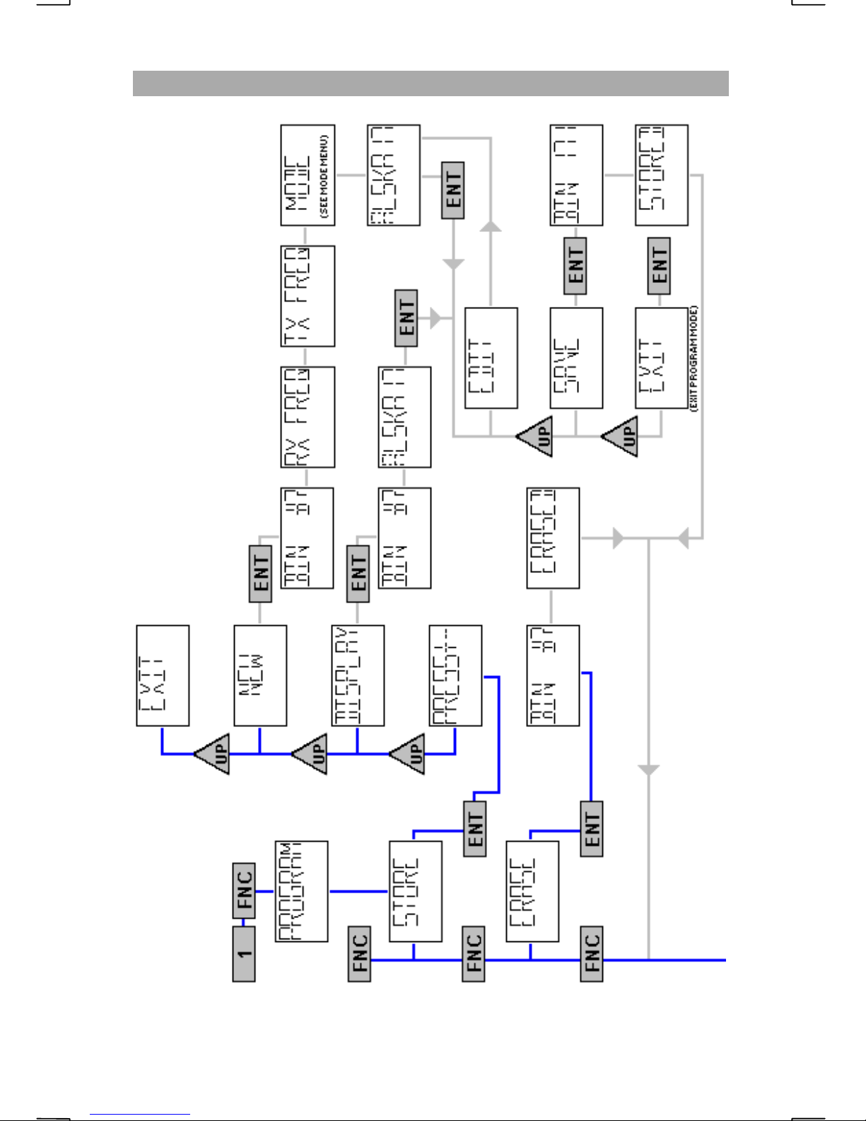
Key Chart 1 - PROGRAM MENU 1...................................................................15
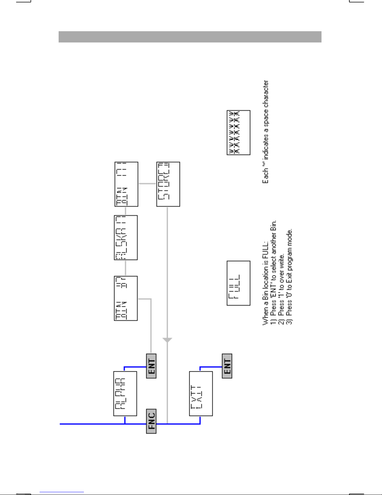
Key Chart 2 - PROGRAM MENU 2...................................................................16
Key Chart 3 - MODE MENU .............................................................................30
Key Chart 4 - POWER MENU ...........................................................................32
Key Chart 5 - DIMMER MENU.........................................................................34
Key Chart 6 - SETUP MENU 1..........................................................................37
Key Chart 7 - SETUP MENU 2..........................................................................38


GENERAL OPERATIONS
TECHNICAL SPECIFICATIONS
DIMENSIONS
3.9” H x 10.5” W x 10.9” D
99mm H x 265 mm W x 278mm D
WEIGHT
10 Lbs.
4.5 Kgs.
:
ELECTRICAL
Type Acceptance FCC Parts 80, 87, 90
FCC Identifier BZ6SEA235
Frequency Range (TX) 1.605 - 29.999 MHz
Operating Temperature -30 degrees to +60 degrees C
Frequency Stability
Operating Modes J3E, R3E, H3E (2182 KHz)
:
:
(RX) 0.490 - 29.999 MHz
± 10 Hz
A1A (CW), F2B (TELEX)
Primary Voltage 13.6 V DC ± 15% (11.6 - 15.6 V DC)
Negative Rail Common to Chassis
Current Drain Receive Standby 1 Amp
Receive Full Audio 1.5 Amps
Transmit Voice 11 Amps
Transmit Two-Tone 17 Amps
Transmit TELEX 22 Amps
Output Impedance 50 ohms
Transmitter Output Power R3E, J3E 150 Watts PEP
F2B 150 Watts
LOW 50 - 75 Watts
VLOW 25 - 40 Watts
Receiver Sensitivity
Audio Output
≤ 1 µV for 12 dB SINAD
4 W @ ≤ 10% distortion into external
4 ohm load.
1

GENERAL OPERATIONS
GENERAL INFORMATION
CAUTION
Do not attempt to transmit until the radiotelephone has warmed up for at least 3
minutes. Transmitting before the 3 minute warm up period can cause a violation
of the Federal Communications Commission regulations.
!
PROPAGATION
Medium Frequencies (MF) in the range of 300 KHz to 3 MHz propagate far
beyond the horizon. MF frequencies are generally usable within 300 miles
depending on the time of day, atmospheric conditions and man-made noise
levels.
High Frequencies (HF) in the range of 3 MH z to 30 MHz allow communications
over thousands of miles, again subject to the time of day and atmospheric
conditions. Interference tends to be more of a problem than on Very High
Frequencies (VHF) in the range of 30 MHz to 300 MHz.
To furthe r understand MF/HF propagation, SEA’s “Mariners G ui de to Single
Sideband” (MAN-0001-001) is highly recommended reading.
INSTALLATION (RF grounding & DC connections)
A radio frequency (RF) ground with a minimum of 100 sq. ft. is required for
proper operation. Thi s ground system is not unique to SEA equipment. All
marine MF/HF radios have the same installation requirements for maximum
efficiency. Every connection to the ground should be made with a minimum of
2” wide copper strap. Proper wire size must be used between the radio and
power supply to prevent the DC (direct current) voltage at the radio from
dropping below 11.5 volts during transmit conditions. Should this occur, the
radio will drop to low power during transmit to prevent distorted transmissions.
It is recommended that an authorized SEA dealer perform the installation of your
MF/HF equipment to assure proper operation. For complete installation
instructions, refer to the “SEA 235 Installation Manual” (OPR-235-INST)
supplied with the radio.
RADIO PROTECTION
The SEA 235 monitors radio conditions such as DC supply voltage, internal
temperature and antenna VSWR. When these conditions are outside the preset
limits, the radio will revert to low power (approximately 75 Watts). The
display’s LOW indicator will light to indicate this condition. If this should occur
during an EMERGENCY situation, pressing will
override the monitoring sensors and allow FULL output power. The radio will
stay in the EMERGENCY OVERRIDE condition until the radio power is recycled.
6
6
FNC
2

GENERAL OPERATIONS
UNDERSTANDING CHANNEL MEMORY
CHANNELS
Nearly 1000 frequency pairs are stored as permanent channels in the SEA 235.
These channels are recalled by their assigned ITU or SEA channel number. ITU
numbers are known internationally and include all duplex frequency pairs
starting at 4 MHz and ending with 25 MHz. SEA numbers are assigned to those
frequencies that do not have an assigne d ITU number. Currently all 2 to 3 MHz
frequencie s and all simplex frequencies are assigned SEA channel numbers.
It is important to note that not all radios use the same channel numbers for
simplex or 2 to 3 MHz frequencies. Some radios use an “A”, “B”, “C” channel
assignment for frequencies not assigned an ITU channel number. For example,
if you refer to the SEA simplex channel 451 during communications, the person
you are communicating with may not have a channel 451. Their radio may have
the same frequency (4146.0 KHz) assigned to channel “4A”. For reliable
communications, always refer to t he frequency when referencing simplex
channels or frequencies below 4 MHz.
BINS
In addition to the permanent memory, 200 user programmable channels known
as bins have been assigned for “scratchpad” memory. Approximately 170 of
these 200 channels have been programmed by SEA but may be changed at any
time. Bins may be programmed with any frequency, mode of transmission and
given a name tag be si des a bin number.
SCAN CELLS
Consecutive bin numbers that have the same first three characters in their name
tag, are known as “scan cells”. SEA has programmed 170 of the 200 possible
bins into 23 different scan cells. Scan cells may be as short as one bin or as long
as 200 bins but should be kept to a reasonable length for scanning efficiency.
Each scan cell is organized with frequency pairs that are related to one another.
For example, bins 13 through 30 have been programmed with frequencies
assigned to the coast station KMI. Since the name tag’s first three characters are
“KMI”, and the bins are consecutively numbered, the bins may be scanned as a
group. If the bins do not have the same first three characters, the scan cell will
be split into two different cells. For instance, if bin 20 is renamed to “SEA 1”,
the KMI scan cell will be split into two cells. One cell will contain bins 13
through 19, while the other cell will contain bins 21 through 30. Bin 20 will be a
single channel scan cell called “SEA”. Scanning “KMI” could be done by
scanning bins 13 through 19 OR bins 21 thr ough 30 but not both at t he same
time.
Care should be given that a scan cell is not split unintentionally. Bins that will
not be scanned can be given any descriptive name tag.
3
GENERAL OPERATIONS
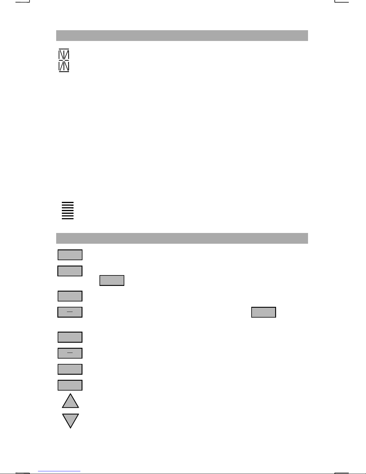
LCD DISPLAY CHARACTERS
Alphanumeric digits display channel numbers, frequencies and menus.
NB
TX
TND
LOW
AME
LSB
TLX
SQL
The NOISE BLANKER is activated.
The radio is in TRANSMIT.
The attached coupler has finished the tune process.
Indicates ½ output power during transmit when on steady or
output power when flashing.
¼
The radio will transmit a reduced carrier (H3E) of approximately 40W.
This mode is only available on the emergency frequency 2182.0 KHz.
Both transmit and receive will use LOWER SIDEBAND mode.
TELEX (J2B) mode will be used for transmit and receive.
The receiver SQUELCH is activated.
Relative output power when transmitting and audio signal strength
during receive. No bars indicates weak signal.
FRONT PANEL CONTROLS
PWR
0 – 9
ALRM
NB
SEND
SQL
CH
FX
FNC
ENT
UP
DN
Toggles power on/off.
Used to enter channel/frequency information and menu selections.
0
2182
used alone, recalls emergency frequency 2182.0 KHz.
Toggles alarm generator test on/off.
Enables receiver noise blanker. When used with ,
ALRM
transmits alarm signal.
Toggles squelch on/off.
Toggles display to show channel / bin #, frequency, or alpha name.
Accesses function menus a nd other function commands.
Selects displayed funtion menu or completes keyed entry.
Increases receiver frequency and scrolls selected function options.
Decreases receiver frequency and scrolls selected function options.
4
SEA 235
HF/SSB DIGITAL
RADIOTELEPHONE
NBTXTND
LOW
AME
LSB
GENERAL OPERATIONS
1
2
TLX
SQL
4
7
FNC
2182
3
5
6
8
9
0
ENT
UP
DN
PWR
ALRM
NB
SEND
SQL
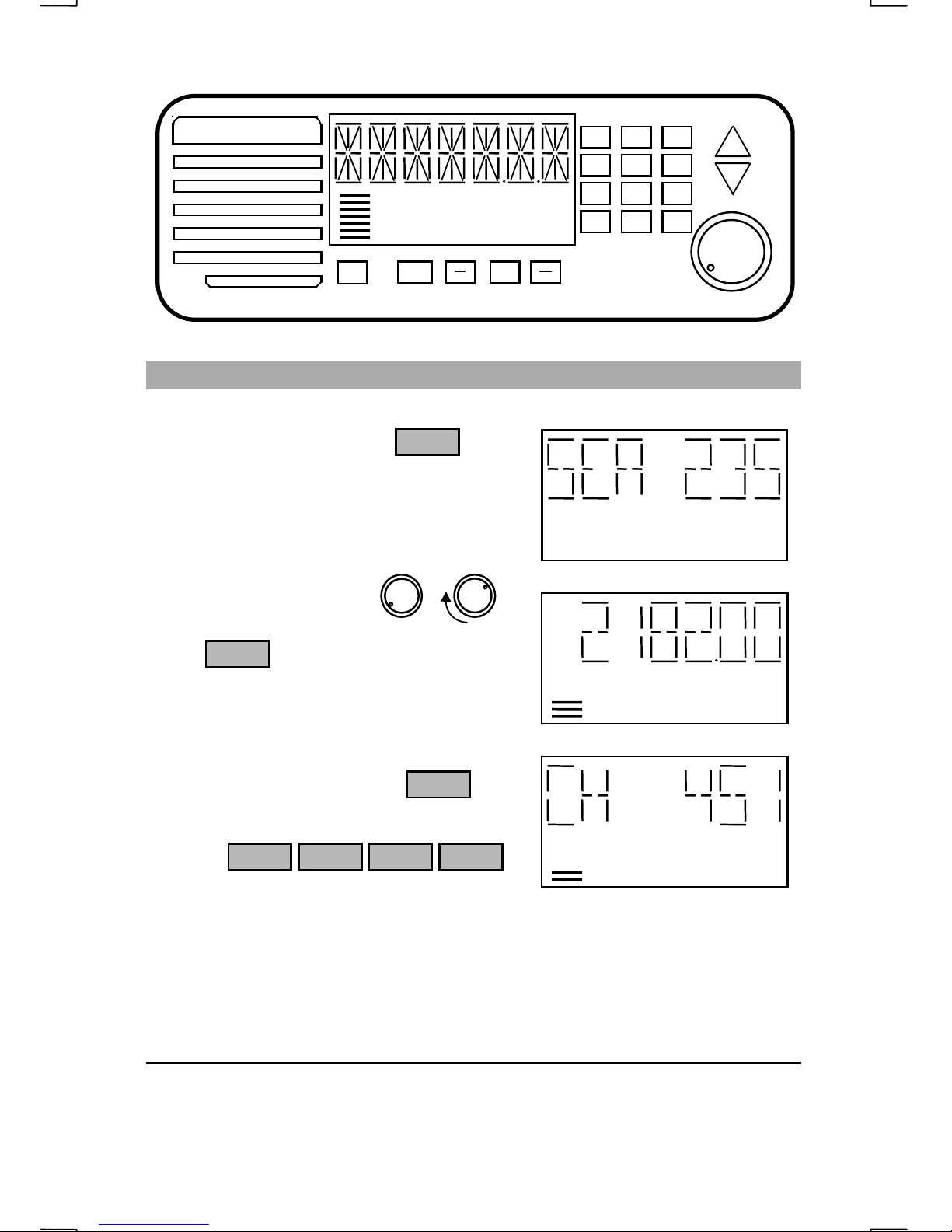
BASIC OPERATION
To turn the radio on, press
Wait 3 minutes for the synthesizer freque ncy
to stabilize before transmitting.
Rotate the volume control clockwise to
increase the volume level.
Press to activate the squelch.
SQL
PWR
CH
FX
TND
LOW SQL
Enter the desired channel number in three or
four digit form, followed by the key.
e.g.
4 5 1 ENT
ENT
LOW SQL
The display will show the channel number for 2 seconds then change to display
the receive frequency.
Your SEA 235 is now set to transmit and receive on the selected channel.
For instructions on enabling other radio functions, see the table of contents for
the page number corresponding to the specific function.
Illustrations in this manual reflect the use of an attached SEA 1635 tuner. Differences in
tuner choice or radio programming may produce varying displays.
5
GENERAL OPERATIONS
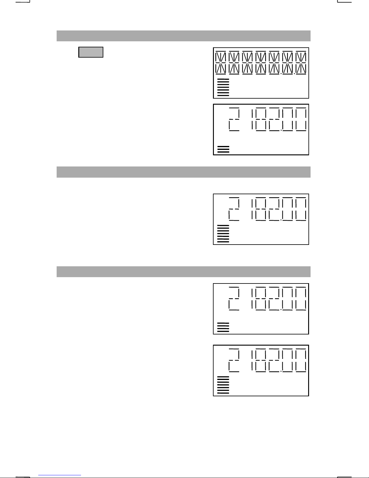
TURNING THE RADIO ON
Press
All display segments will be shown for a short
period followed by the radio model number,
then the controller (CT) and transceiver (RT)
software versions. The radio will then be set to
the MARINE mode on international emergency
frequency 2182.0 KHz using USB, J3E mode.
Wait 3 minutes for the synthesizer freque ncy to
stabilize before transmitting.
PWR
NBTXTND
LOW
LOW
AME
LSB
TLX
SQL
OPERATING THE TRANSMITTER
Keying the microphone push-to-talk button will switch the transmitter circuits
on, indicated by the “TX” indicator appearing
on the display. Speak in a normal voice with
your lips about one eighth of an inch away
from the microphone. Do not shout. Shouting
reduces intelligibility. The number of bars
displayed will change as the operator talks.
TX LOW
THE TUNED INDICATOR
The display’s “TND” indicator shows that the
SEA 1612 series, SEA 1635 or SEA 1631
antenna tuner has successfully matched the
antenna to the radio for maximum radiated
power. When the radio tuner mode is enabled,
entering a frequency or channel will cause the
“TND” i n dicator to ext inguish and the “LOW”
indicator to appear. Speaking into the
microphone when the PTT is pushed will allow
the tuner to find a match. The “TND” indicator
will be displayed and the “LOW” indicator will
extinguish allo wing full output power.
If a frequency or channel has never been used, the “match” will take slightly
NOTE
longer.
:
TX LOW
TND
TX
6
GENERAL OPERATIONS
DEMAND TUNE
When the tuner senses a high VSWR, it will attempt to match the antenna
automatically during transmit. The Demand Tune function signals the tuner to
undergo a complete tune cycle even with an acceptable VSWR. This may be
needed on those rare occasions when the “TND” indicator does not appear or
when the operator suspects the match could be better. For the Demand Tune
function to operate, the SEA 1612C or SEA 1635 tuner must have the ‘DTN’
terminal connected to the SEA 235’s rear panel accessory connector P3 pin 10
(DMD TUNE). The ‘TUNER’ option in the radio’s “SETUP” menu must also
be pro grammed to “TNR ON”. Better tunes may occur using Demand Tune.
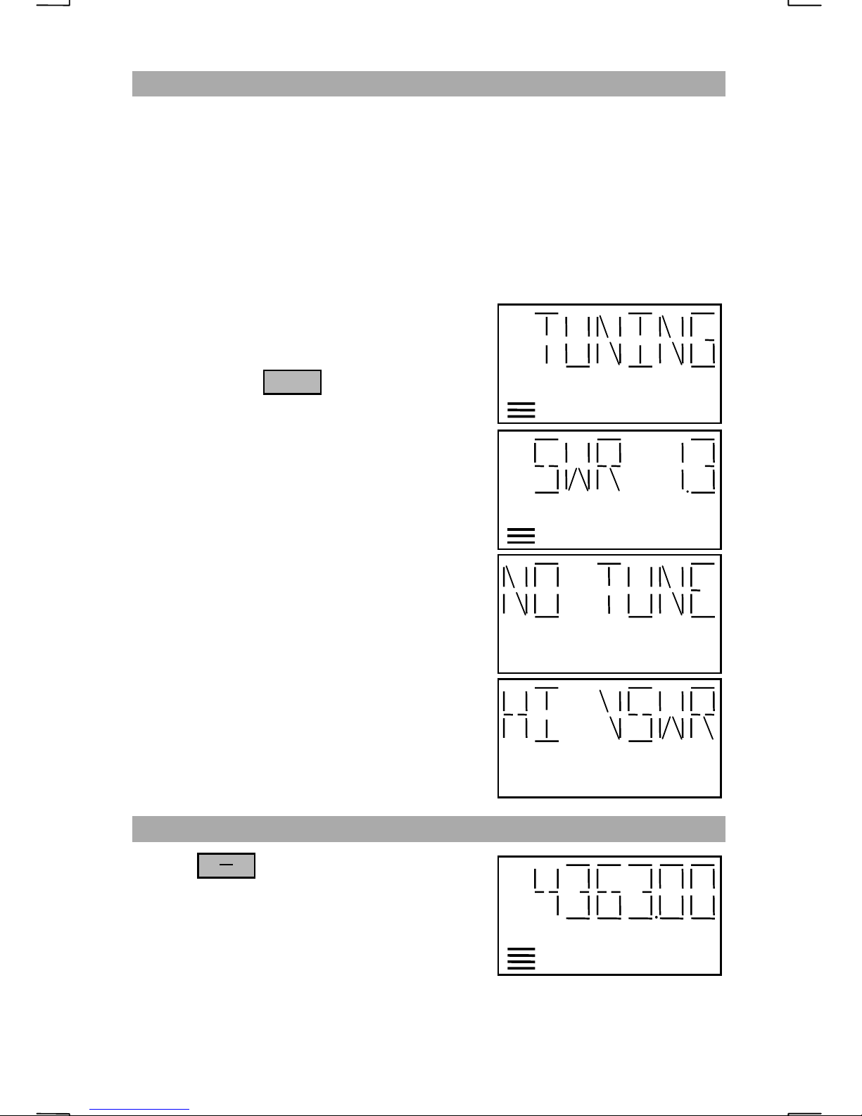
To Demand Tune, key the radio by holding the
PTT button on the microphone down, then
press and release to start the tune
cycle.
The “TND” indicator will turn off, the “LOW”
indicator will turn on and the radio will show
“TUNING”.
FNC
TX LOW
When the tuner has successfully completed the
match, the “LOW” indicator will disappear as
the “TND” indicator appears and the display
will show the VSWR. Release the microphone
PTT.
In the event that the tuner can not find a match
in 15 seconds, the radio will stop transmitting
and the display will read “NO TUNE”.
When tuning with voi ce, “HI VSWR” will
occasionally be displayed until the tune cycle
has successfully completed the antenna match.
NOISE BLANKER OPERATION
Use the key to toggle the noise
blanker on / off. The “NB” indicator shows the
noise bla nker is on. The noise blanker will
help reduce impulse noise that may be caused
by on board equipment such as a bilge pump or
refrigerator compressor.
NB
SEND
TND
TX
TX LOW
TX LOW
NB TND
7
GENERAL OPERATIONS
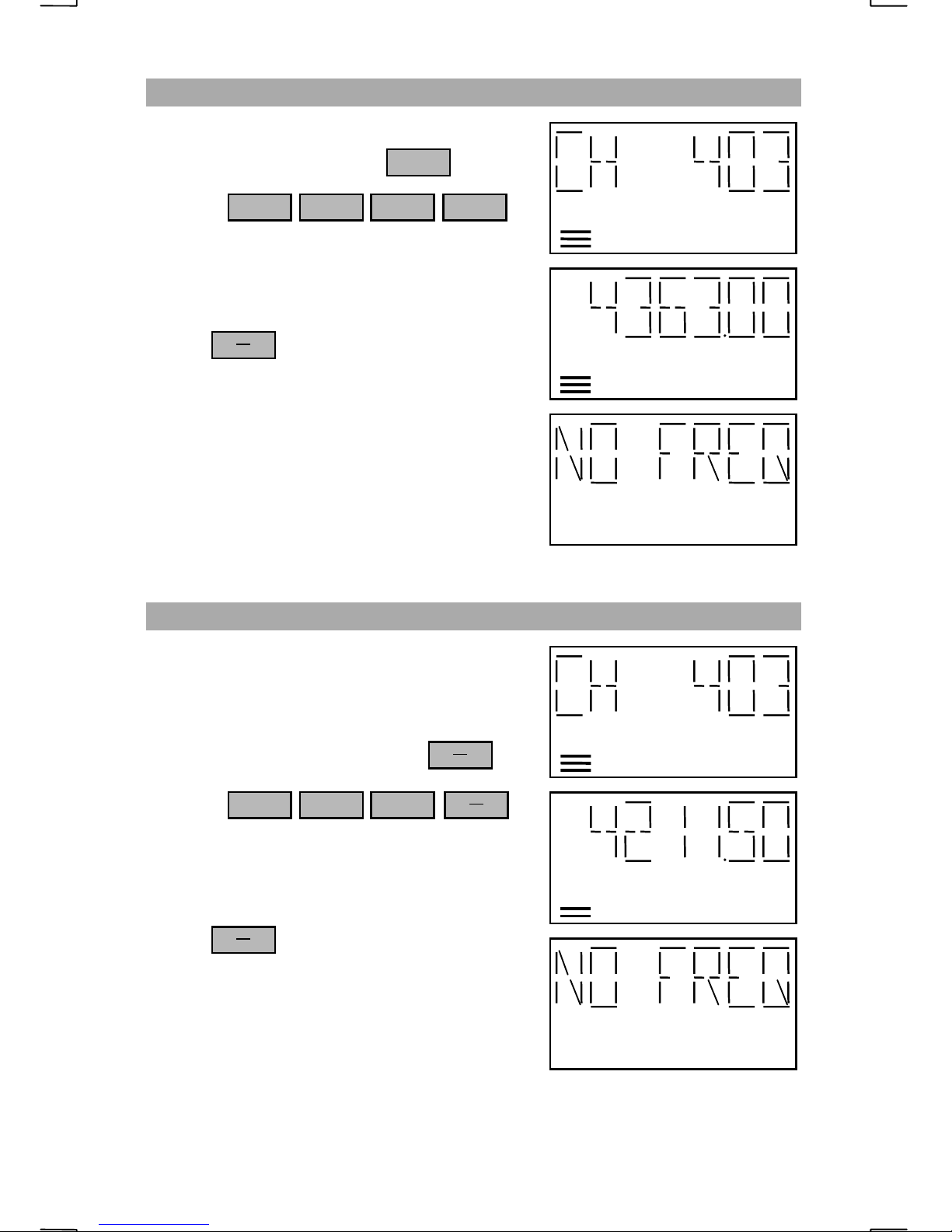
SELECTING A VOICE CHANNEL
Enter the desired three or four digit ITU/SEA
channel number followed by
ENT
e.g.
4
0
2182
3 ENT
The display will show the channel entered
followed by the receive frequency for the
selected channel.
Press to switch between the
CH
FX
channel number display and the frequency
display.
When the microphone PTT button is pressed,
the transmit frequency will be displayed when
in frequency display mode.
If the channel does not exist, “NO FREQ” is
displayed.
SELECTING A TELEX CHANNEL
LOW
LOW
The SEA 235 is capable of telex operations
when used with an appropriate modem.
Enter the desired three or four digit ITU/SEA
telex channel number followed by
e.g.
4
0
2182
3
CH
FX
CH
FX
The display will show the channel entered
followed by the receive frequency for the
selected channel.
Press to switch between the
CH
FX
channel number display and the frequency
display.
When the microphone PTT button is pressed,
the transmit frequency will be displayed when
in frequency display mode.
If the channel does not exist, “NO FREQ” is displayed.
TLX
LOW
TLX
LOW
8
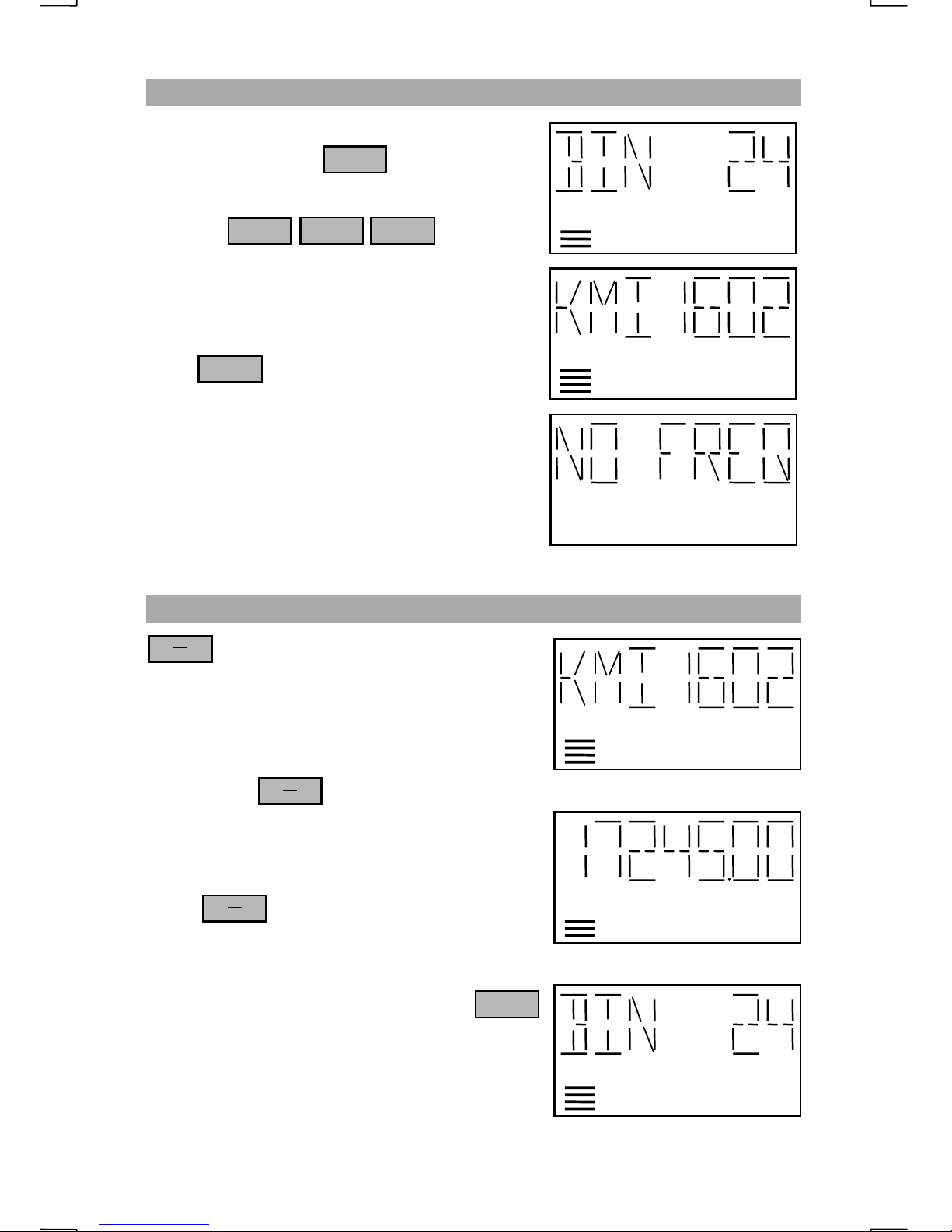
SELECTING A CHANNEL BY BIN NUMBER
Enter the desired one, two or three digit bin
number followed by
ENT
GENERAL OPERATIONS
e.g.
2 4 ENT
The display will show “BIN 24” for 1 second
followed by the name tag of the bin selected.
Press to cycle between the channel
CH
FX
display, frequency display, and alphanumeric
name tag displays.
When the microphone Push To Talk button is
pressed, the transmit frequency will be
displayed when in frequency display mode.
If the bin is not programmed, “NO FREQ” is
displayed.
CHANGING THE DISPLAY VIEW
CH
FX
between the alphanumeric name tag, channel
number and the associated frequency for that
channel.
is used to change the display view
LOW
LOW
TND
For Bins, the key will change the
CH
FX
display view between the Alphanumeric name
tag, freq uency and bin number.
When is pressed while on 2182.0 KHz,
CH
FX
the display will briefly show “EMER 0”.
To display the transmit frequency, press
to have the display show the receive frequency.
Press the microphone PTT to have the
transmitter frequency displayed.
ALPHANUMERIC NAME TAG
TND
FREQUENCY VIEW
CH
FX
TND
BIN / CHANNEL VIEW
9
GENERAL OPERATIONS
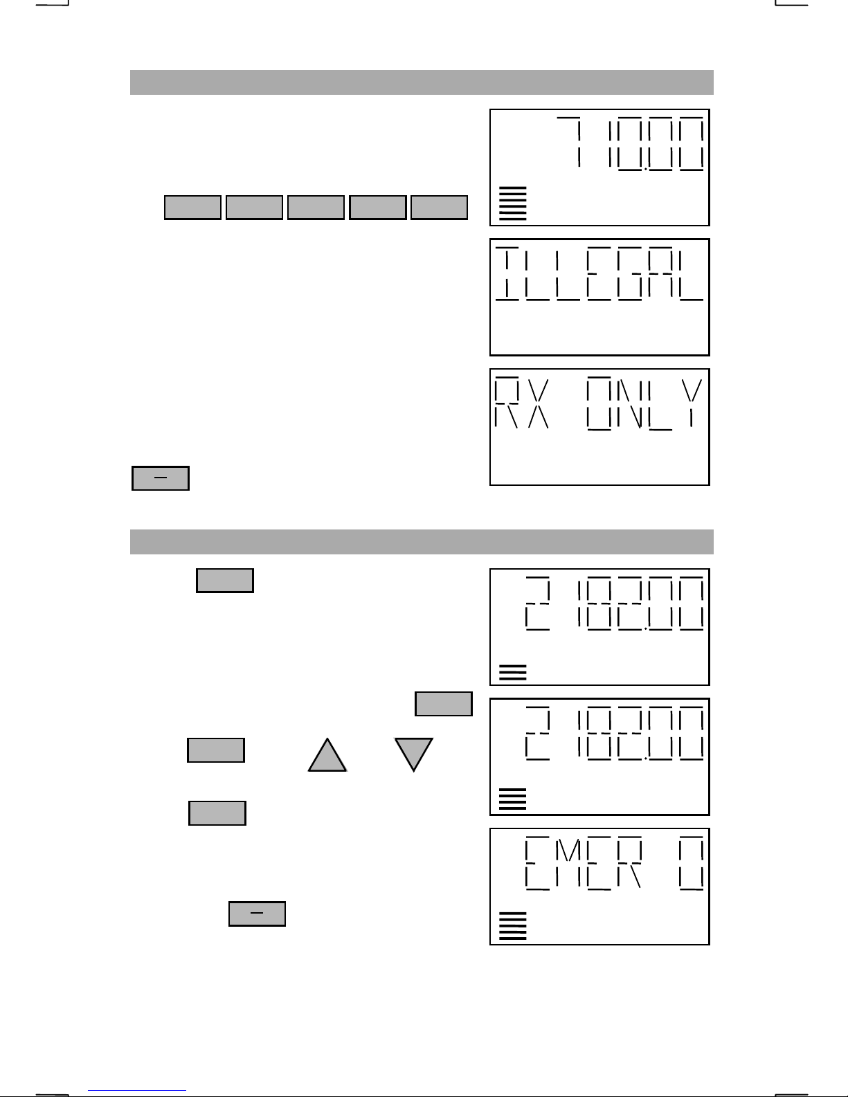
ENTERING A RECEIVE ONLY FREQUENCY
Enter any frequency using four, five, or six
digits followed by “ENT”.
e.g.
7
0
2182
0
2182
ENT1
If the frequency entered is less than 490.0 KHz
or greater than 29999.99 KHz, the radio will
prompt “ILLEGAL” and revert to the last
channel entered.
When trying to transmit on a receive only
frequency, the display will show “RX ONLY”.
CH
FX
will not operate in receive only mode.
SELECTING THE EMERGENCY CHANNEL
Press
0
2182
LOW
LOW
The radio will switch to the international
emergency frequency of 2182.0 KHz using
USB, J3E mode.
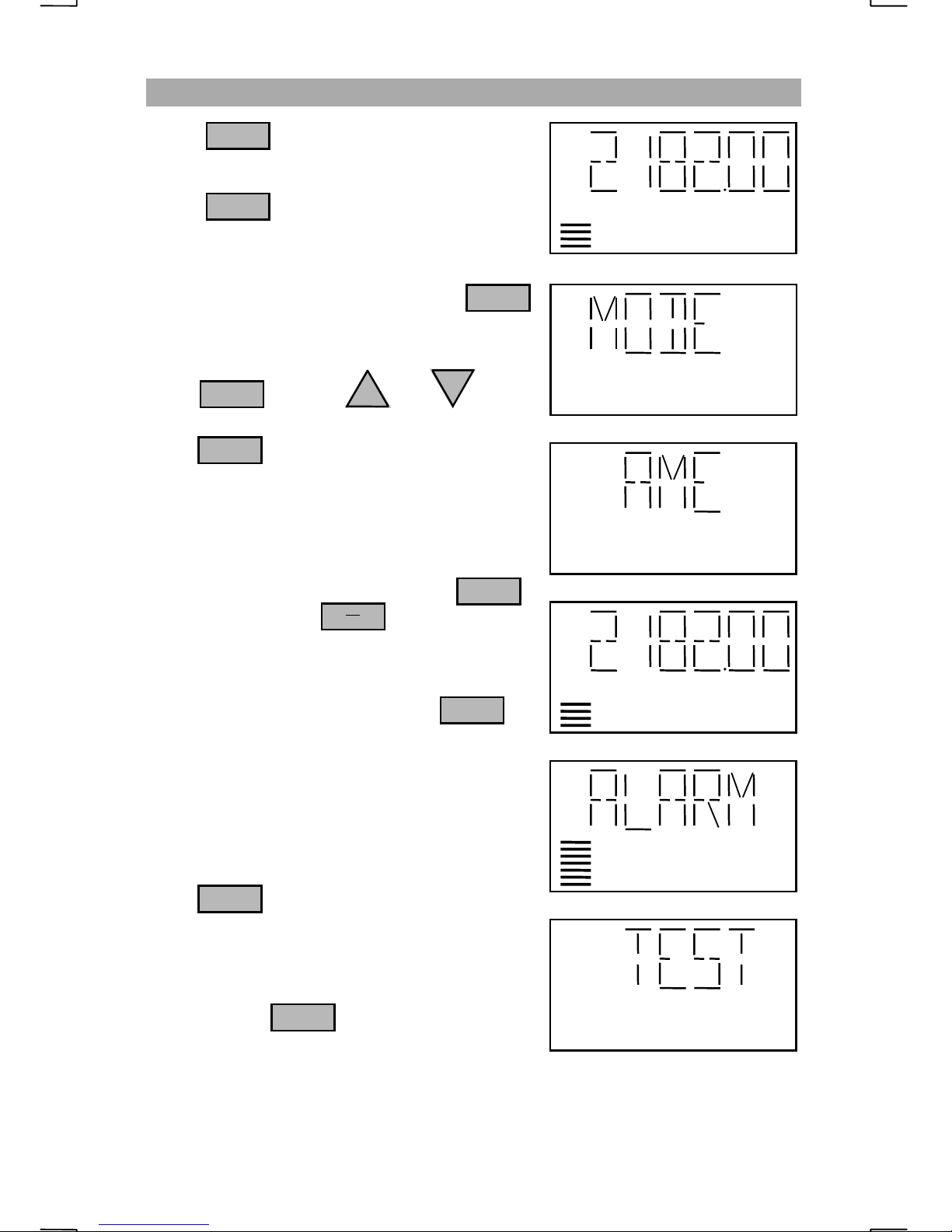
If H3E (AME) mode is required, press
FNC
repeatedly until “MODE” is displayed.
Press then or
ENT
UP
DN
(“PRESS+-”) repeatedly until “AME” appears.
Press
ENT
The radio is now ready to transmit an AME
signal using a 40 W carrier.
Pressing the will briefly show the
CH
FX
assigned channel number, “EMER 0”.
LOW
AME
LOW
AME
LOW
10
GENERAL OPERATIONS
SENDING THE DISTRESS ALARM SIGNAL
Press to stop any entry in progress.
Press to select 2182.0 KHz.
If H3E (AME) mode is required, press
ENT
0
2182
FNC
repeatedly until “MODE” is displayed.
DN
Press then the or key
ENT
UP
repeatedly until “AME” appears.
Press to select AME mode .
ENT
AME is only available on 2182.0 KHz.
LOW
To transmit the alarm signal, hold the
key down then press
NB
SEND
ALRM
The radio will transmit the alarm for 45
seconds unless stopped by pressing
ALRM
The two tone alarm signal can be transmitted
on all available frequencies. It is not necessary
to use 2182.0 KHz for the alarm generator to
function.
To test the alarm without transmitting a signal,
press
ALRM
You will hear the alarm tones through the
speaker but no signal will be transmitted. This
will continue for 45 seconds unless stopped by
again pressing
ALRM
TX
LOW
TND
LOW
LOW
AME
AME
AME
11
GENERAL OPERATIONS
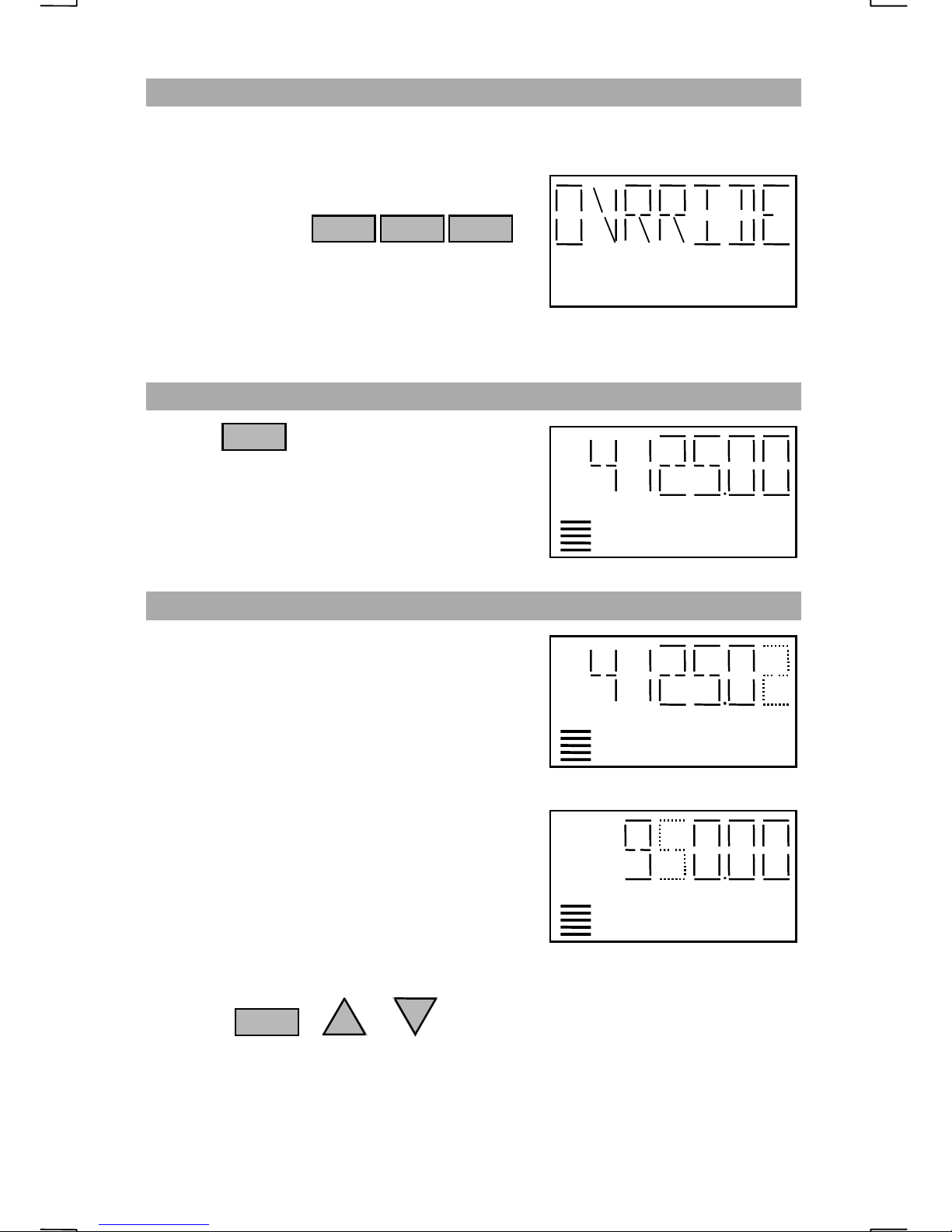
OVERRIDE
When operating conditions are outside the normal preset limits, the radio will
revert to low power (approximately 75 Watts). The display’s “LOW” indicator
will light to indicate this condition. If this
should occur during an EMERGENCY
situation, pressing
6 FNC6
will override the monitoring sensors and allow
FULL output power. The radio will stay in the
EMERGENCY OVERRIDE condition until the
radio power is re-cycled. If the power has been reduced manually or the tuner
fails to match the antenna, the override will not increase to full power.
SQUELCH OPERATION
Use the key to toggle the squelch
SQL
on / off. The “SQL” indicator shows the
squelch is on. The speaker will mute after
approximately 2 seconds. Varying audio
frequencies will open the squelch but not a
steady tone.
CLARIFIER OPERATIONS
In the “MARINE” operating system, the
clarifier tuning range is limited to ±200 Hz
when used on any Bin or ITU/SEA channel.
When the radio is turned on, the clarifier step
size will default to 10 Hz.
Any “receive only” frequency or any frequency
used in the “AMATEUR” operating system has
an unlimited clarifier range and can be changed
in steps of 10 Hz, 100 Hz, 1 KHz, or 10 KHz.
TND
SQL
TND
SQL
Flashing clarifier set for 10 Hz (default)
To change the clarifier resolution
Select “1” for 10 Hz steps, “2” for 100 Hz
steps, “3” for 1 KHz steps or “4” for 10 KHz
steps then “UP” or “DN”.
e.g. Press or to have the clarifier change in 100 Hz steps.
2
The chosen clarifier digit will blink for 2 seconds to indicate the selection. If the
digit does not blink, it is not a valid selection for the current mode and the
setting will not change .
:
LOW SQL
Flashing clarifier set for 10 KHz
DN
UP
12
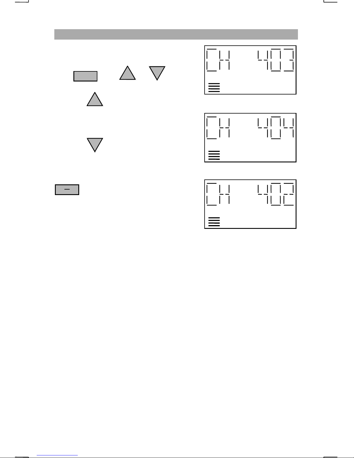
OPERATING THE MEMORY BROWSE
Browse enables a manual scan of all channels
or bins programmed in the radio.
DN
Press then or
9
UP
GENERAL OPERATIONS
LOW
Pressing will change the channel to the
UP
Starting at ITU channel 403
next channel in memory. The display will then
change to frequency mode when an ITU/SEA
channel is selected.
Pressing will change the channel to the
DN
previous channel in memory. The display will
then change to frequency mode when an
Next ITU channel in memory is 404
LOW
ITU/SEA channel is selected.
CH
FX
will toggle between bin/channel,
frequency and name tag display modes.
Memory browse will not scan through bins and
channels at the same time. If a channel is
selected and you wish to browse the bins, select
Previous ITU channel in memory is 402
LOW
a bin number fr om which to start.
When the last bin or channel is selected, the next step will go to the beginning of
the bin or channel list.
To exit memory browse, press the microphone Push To Talk button briefly,
adjust the clarifier step size or recycle the radio power.
13
ADVANCED OPERATIONS
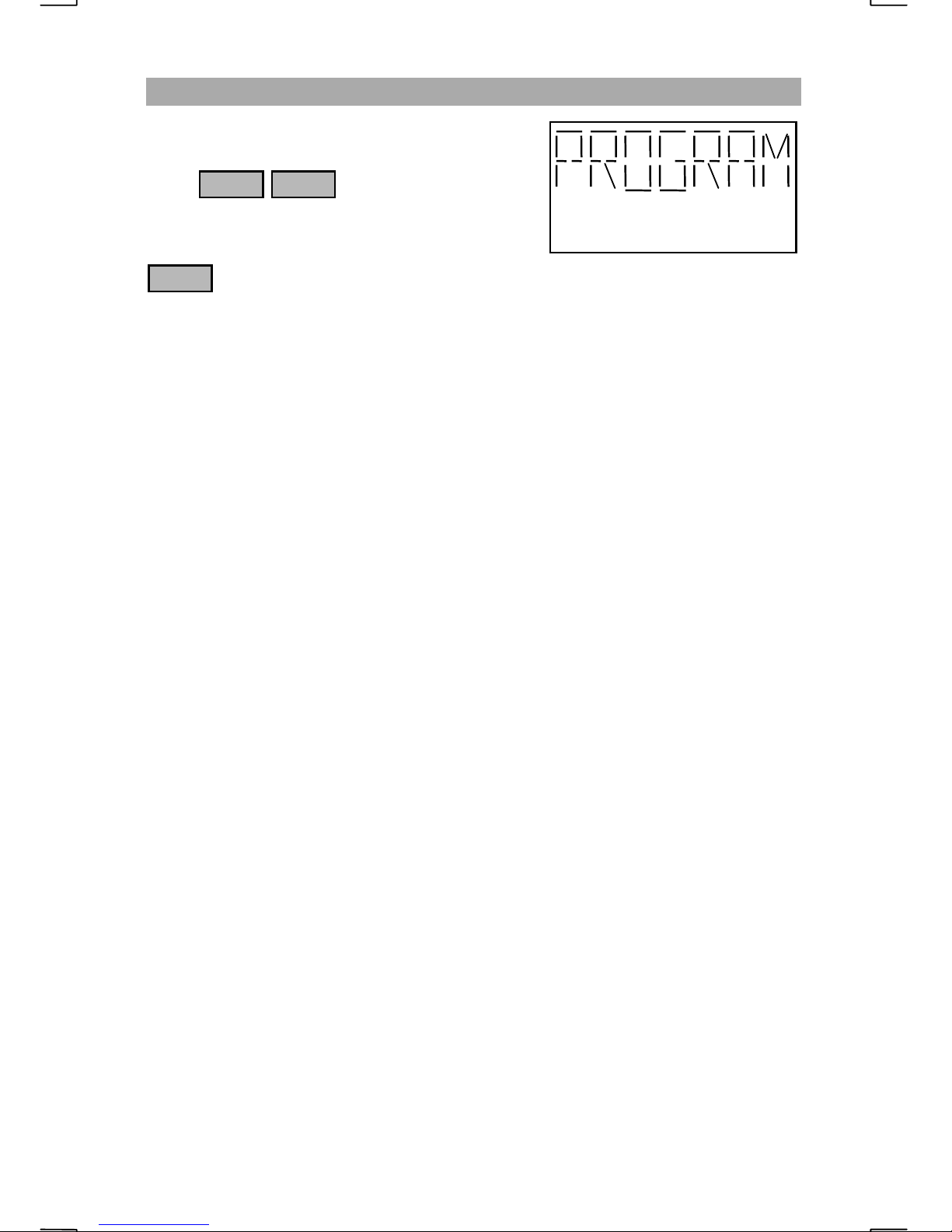
SELECTING THE PROGRAM MENU
To enter the program mode
press
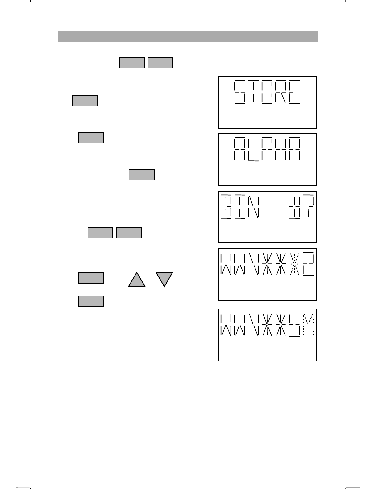
The display will show “PROGRAM”, followed
by the first program option. Every time the
FNC
option. The options available for programming are “STORE”, “ERASE”,
“ALPHA” and “EXIT”.
1 FNC
key is pressed, the radio will step to the next programming menu
“
STORE
” will allow saving either the displayed information or entering a new
transmit / receive frequency pair and operating mode. If a name tag other than
the suggested is used (other than “NEW”), a new scan cell will be created.
“
ERASE
“
ALPHA
” deletes the bin number entered. Erasing a bin will split a scan cell.
” is the name tag edit routine. This routine is also used when storing a
display or new frequency pair.
“
EXIT
” will exit the program menu. No channel or frequency information will
be stored when EXIT is selected.
Care should be given to the bin number used when programming frequencies.
NOTE
The bin number and name tag will affect how channels are browsed and scanned.
:
Consecutive bin numbers that have the same first three characters in their name
tag, are known as “scan cells”. SEA has programmed 170 of the 200 possible
bins into 23 different scan cells. Scan cells may be as short as one bin or as long
as 200 bins but should be kept to a reasonable length for scanning efficiency.
Each scan cell is organized with frequency pairs that are related to one another.
For example, bins 13 through 30 have been programmed with frequencies
assigned to the coast station KMI. Since the name tag’s first three characters are
“KMI”, and the bins are consecutively numbered, the bins may be scanned as a
group. If the bins do not have the same first three characters, the scan cell will
be split into two different cells. For instance, if bin 20 is renamed to “SEA 1”,
the KMI scan cell will be split into two cells. One cell will contain bins 13
through 19, while the other cell will contain bins 21 through 30. Bin 20 will be a
single channel scan cell called “SEA”. Scanning “KMI” could be done by
scanning bins 13 through 19 OR bins 21 thr ough 30 but not both at t he same
time.
Care should be given that a scan cell is not split unintentionally. Bins that will
not be scanned can be given any descriptive name tag.
14
ADVANCED OPERATIONS
PROGRAM MENU SELECTIONS
Key Chart 1 - PROGRAM MENU 1
15
ADVANCED OPERATIONS
PROGRAM MENU SELECTIONS
(cont.)
Key Chart 2 - PROGRAM MENU 2
16
ADVANCED OPERATIONS
STORING THE DISPLAYED FREQUENCY
After selecting a channel or commonly used frequency, the displayed
information may be saved into any bin location. This will include the mode of
operation such as LSB, receive only, etc. To save the displayed information,
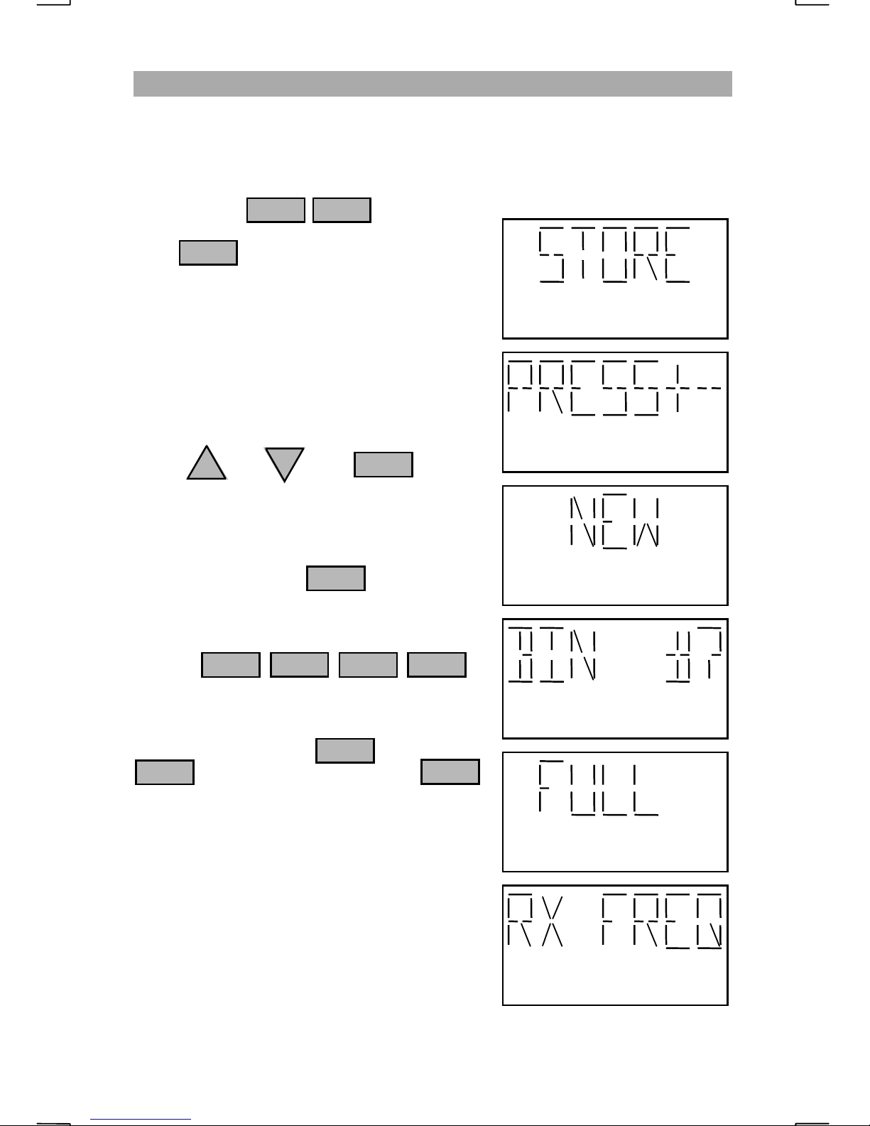
press to enter the program mode.
1 FNC
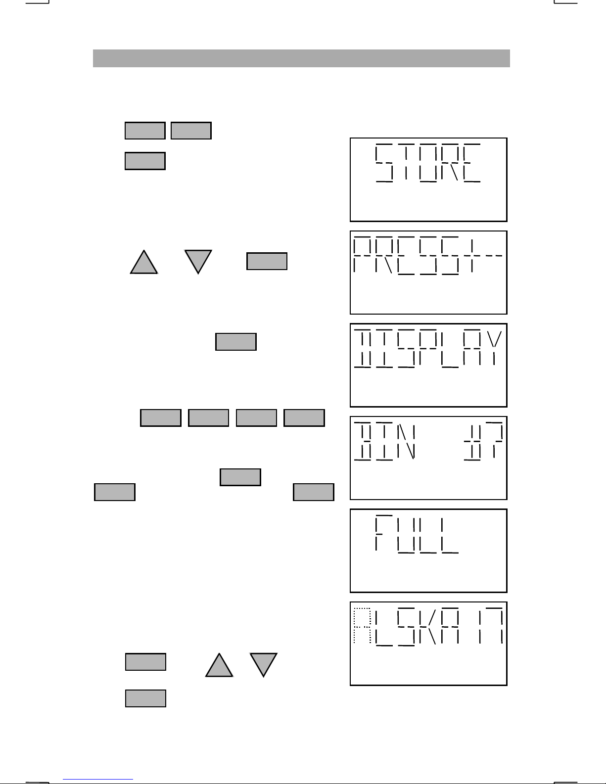
Press when “STORE” appears on the
ENT
display.
You will be prompted to “PRESS+-” for
selecting the type of information to store.
Press or then when
UP
DN
ENT
“DISPLAY” appears.
Enter any bin number for storing the displ ayed
frequency fo llowed by
ENT
e.g. To save the displayed information to bin
number 171 press:
7
11
ENT
If the bin is “FULL”, you may overwrite the
information by pressing or press
ENT
to select a new bin. Pressing
1
0
2182
will exit the programming mode.
Because bin 170 is factory programmed as
“ALSKA16”, the radio will make the
assumption that the operator will want this
channel’s name tag to be ALSKA17.
The character that is ready to edit will blink.
If you wish to leave the character the same
press . P r ess or to change
ENT
UP
DN
the blinking character.
Press to move to the next character .
ENT
17
Blinking character may be changed
ADVANCED OPERATIONS
STORING THE DISPLAYED FREQUENCY
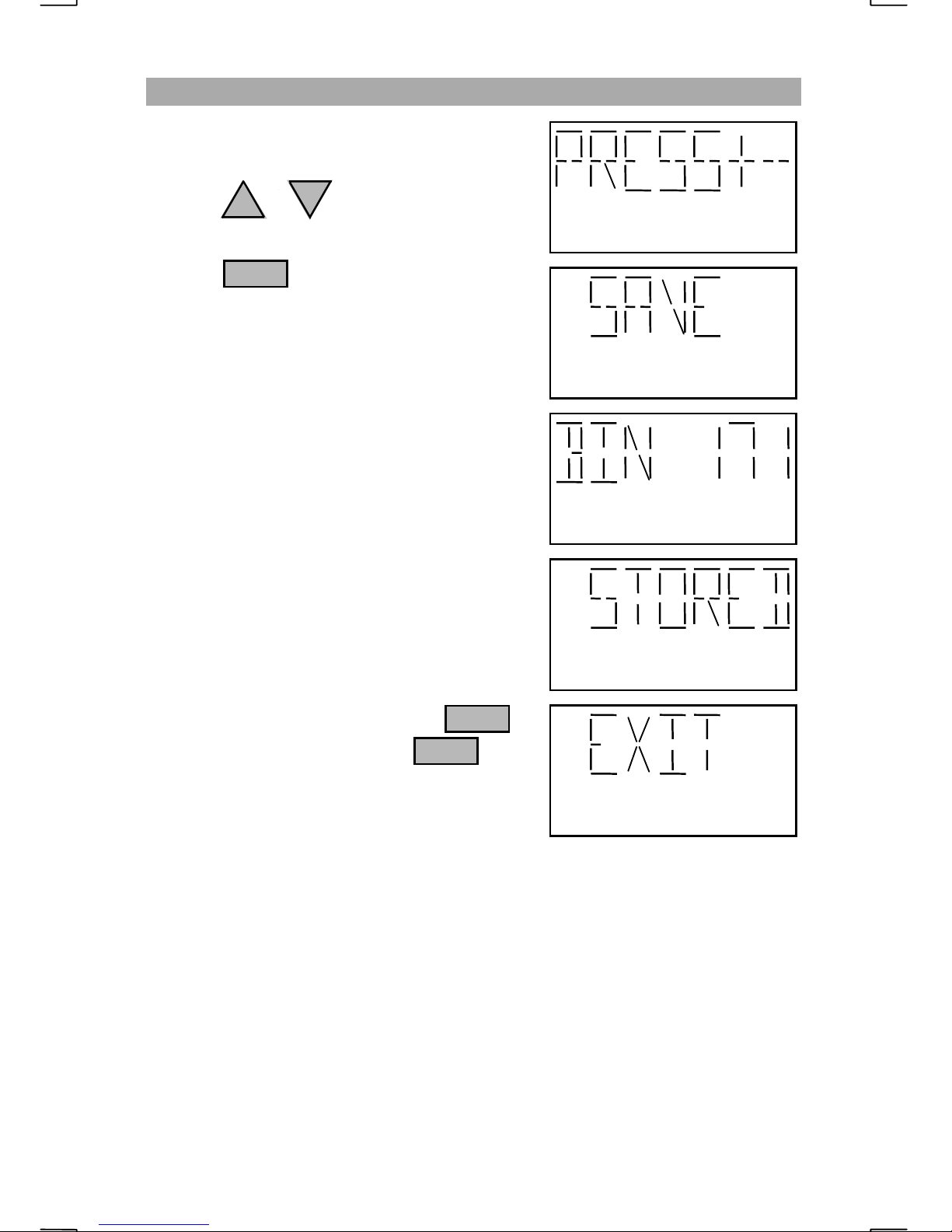
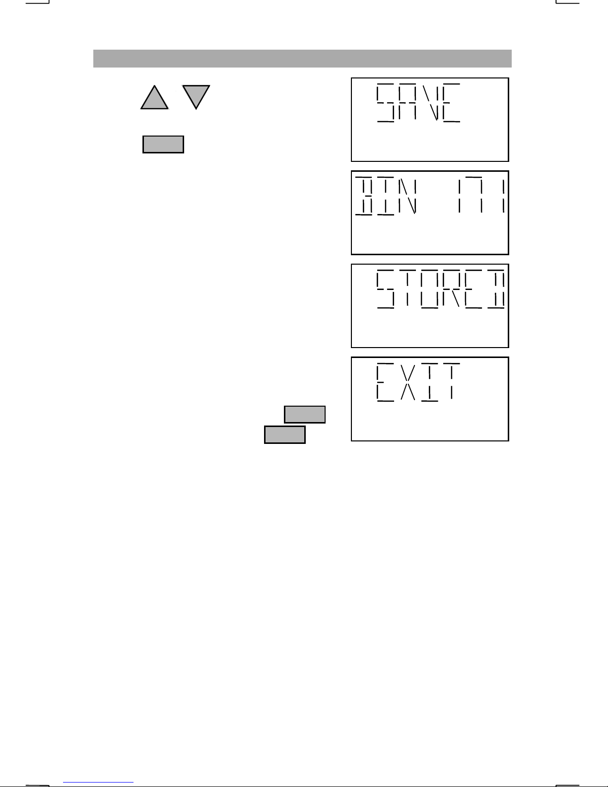
After accepting or editing the name tag, the
operator is again prompted to “PRESS+-”.
Pressing or will cycle through the
UP
final options of “SAVE”, “EDIT” and “EXIT”.
Pressing when “
ENT
will save the information to the bin number
chosen.
“
EDIT
” allows the name tag to be changed or
corrected for the selected bin.
“
EXIT
” will leave the program mode without
saving the information to the selected bin
unless “SAVE” is selected before “EXIT”.
After saving the information, “BIN 171”,
followed by “STORED” will appear indicating
that the information has been saved.
DN
SAVE
” is displayed
(cont.)
The radio will stay in the program mode asking
if the operator wishes to “STORE” another
channel.
To exit the program mode, press the
key to have “EX IT” appear then to
FNC
ENT
restore the radio to normal operations.
18
ADVANCED OPERATIONS
PROGRAMMING A NEW FREQUENCY
The SEA 235 allows the operator to store a new frequency pair that is not the
current displayed frequency. This is useful when more than one bin location is
to be programmed while in program mode. This will include the mode of
operation such as LSB, receive only, etc. To save a new frequency pair to a bin
location, press to enter the program mode.
1 FNC
Press when “STORE” appears on the
ENT
display.
You will be prompted to “PRESS+-” for
selecting the type of information to store.
Press or then when
UP
DN
ENT
“NEW” appears.
Enter the bin number for storing the new
frequency fo llowed by
ENT
e.g. To save the displayed information to bin
number 171 press:
7
11
ENT
If the bin is “FULL”, you may overwrite the
information by pressing or press
ENT
to select a new bin. Pressing
1
0
2182
will exit the programming mode.
When “RX FREQ” is displayed, enter a receive
frequency.
If the receive frequency is not between 490.0
KHz and 29999.9 KHz, “ILLEGAL” will be
displayed.
19
ADVANCED OPERATIONS
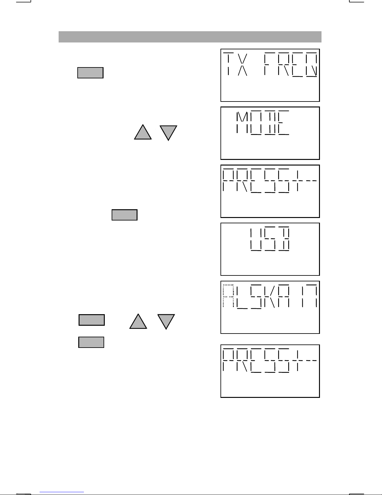
PROGRAMMING A NEW FREQUENCY
Enter the transmit frequency at the “TX FREQ”
prompt. If a receive only channel is needed,
press at the “TX FREQ” prompt. The
transmit frequency must be between 1600.0
KHz and 29999.9 KHz.
The choices for the “MODE” prompt can be
selected by pressing the or keys.
The available modes are “USB”, “LSB”,
“TELEX”, “TLX - GW”, “TLX - PD”,
“AME”, “CW” and “TRUE AM”.
When the required mode of operation is
displayed press
Normally, all marine communications are USB
or TELEX.
0
2182
UP
DN
ENT
(cont.)
Because bin 170 is factory programmed as
“ALSKA16”, the radio will make the
assumption that the operator will want this
channel’s name tag to be ALSKA17.
The character that is ready to edit will blink.
If you wish to leave the character the same
press . P r ess or to change
ENT
UP
DN
the blinking character.
Press to move to the next character.
ENT
After accepting or editing the name tag, the
operator is again prompted to “PRESS+-”.
Blinking character may be changed
20
ADVANCED OPERATIONS
PROGRAMMING A NEW FREQUENCY
Pressing or will cycle through the
UP
final options of “SAVE”, “EDIT” and “EXIT”.
Pressing when “
ENT
will save the information to the bin number
already entered.
“
EDIT
” allows the name tag to be changed or
corrected for the selected bin.
“
EXIT
” will leave the program mode without
saving the information to the selected bin
unless “SAVE” is selected before “EXIT”.
“BIN 171” “STORED” will appear indicating
that the information has been saved.
DN
SAVE
” is displayed
(cont.)
The radio will stay in the program mode asking
if the operator wishes to STORE another
channel.
To exit the program mode, press the
key to have “EX IT” appear then to
FNC
ENT
restore the radio to normal operations.
21
ADVANCED OPERATIONS
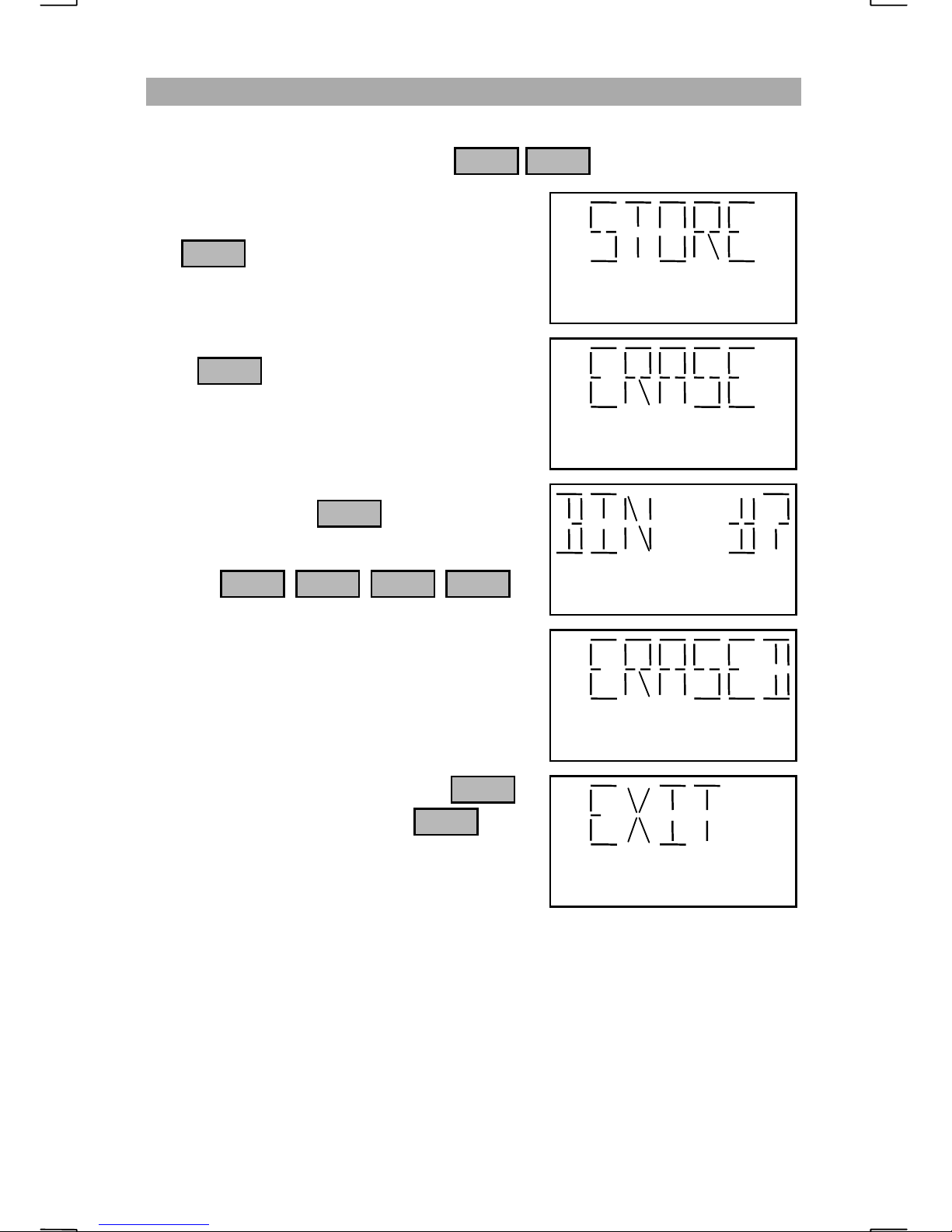
ERASING A CHANNEL
Any frequency pair located in scratchpad memory may be erased. To erase a
frequency pair in a bin location, press to enter program mode.
When “STORE” appears on the display, press
the . key until “ERASE” appears.
FNC
1 FNC
Press at the “ERASE” display.
Enter the b in number of the c hannel you wish
to erase followed by
e.g. To erase bin number 171 press:
The display will show “ERASED” and return
to the beginning of the program mode.
To exit the program mode, press the
key to have “EX IT” appear then to
restore the radio to normal operations.
ENT
ENT
ENT11 7
FNC
ENT
22
ADVANCED OPERATIONS
CHANGING THE NAME TAG OF A BIN
The name tag given to a bin locatio n may be changed at any time. To rename a
bin location, press to enter program mode.
When “STORE” appears on the display, press
the . key until “ALPHA” appears.
FNC
1 FNC
Press at the “ALPHA” display.
ENT
Enter the bin number that is needed to be
renamed followed by . Bins 196 to
ENT
200 are assigned to “NECODE” and can not be
renamed.
e.g. To rename bin number 2 (W WV 2) to
show it is the 5 MHz WWV frequency
press:
2
ENT
The name tag for the selected channel will
appear with the first character blinking.
If you wish to leave the character the same
press . P r ess or to change
ENT
UP
DN
the blinking character.
Press to move to the next character.
ENT
The “*” character indicates a space.
Blinking character may be changed
After the final character is entered, the display
will show “BIN 2” “STORED” and return to
the beginning of the program mode.
Care should be given when renaming bins.
NOTE
When a bin in a scan cell (bins that share the same first three characters in their name tag) is
renamed, the group will be split. For example, bins 13 through 30 have been programmed
with frequencies assigned to the coast station KMI. Since the name tag’s first three
characters are “KMI”, and the bins are consecutively numbered, the bins may be scanned as
a group. If the bins do not have the same first three characters, the scan cell will be split into
two different cells. For instance, if bin 20 is renamed to “SEA 1”, the KMI scan cell will be
split into two cells. One cell will contain bins 13 through 19, while the other cell will contain
bins 21 through 30. Bin 20 will be a single channel scan cell called “SEA”. Scanning
“KMI” could be done by scanning bins 13 through 19 OR bins 21 through 30 but not both at
the same time.
:
23
ADVANCED OPERATIONS
SCANNING A CHANNEL GROUP
Consecutive bin locations that have the same first three characters in their name
tag, are known as “scan cells”. SEA has programmed 170 of the 200 possible
bins into 23 different scan cells. Scan cells may be as short as one bin or as long
as 200 bins but should be kept to a reasonable length for scanning efficiency.
Each scan cell is organized with frequency pairs that are related to one another.
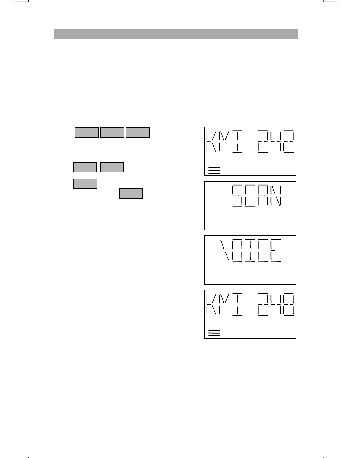
To scan a group of channels, first select a bin within a scan cell.
e.g. To scan the KMI marine operator channels programmed in bin locations 13
through 30, select any bin between 13 and 30 followed by “ENT”.
Press
After the name is shown for the selected bin,
press to start the scan.
Press repeatedly until “
displayed then press
The radio will turn on the “SQL” indicator and
begin the sca n of bins 13 through 30. The first
time through the scan cell, each bin is sampled
for approximately 7 seconds. When the last bin
in the scan cell has been sampled, the scan
speed will increase to 1 bin every ¼ second.
When an audio signal is received, the radio will
open the squelch and stay on channel for as
long as the signal is present and changing.
When “
received, the radio will stay on the channel for
a maximum of 5 seconds and continue to the
next bin even if the signal is still present. This
is a good selection when scanning active
channels.
1 3
2 FNC
FNC
PAUSE
” scan is selected and a signal is
ENT
ENT
VOICE
” is
LOW SQL
“
TELEX
time is required to determine when a valid signal is present.
“
NECODE
special scan mode looks for a 2 KHz tone indicating a possible Necode signal.
The scan speed is increased to approximately 5 channels every ½ second.
” scan reduces the speed to 1 channel every 4 seconds. The additional
” scan is for scanning the Necode bins, 196 through 200. This
24
ADVANCED OPERATIONS
DIRECT FREQUENCY
When a frequency is entered into the radio, it is a receive only frequency. The
‘Direct Frequency’ function allows the operator to input transmit and receive
frequencies along with a mode of operation.
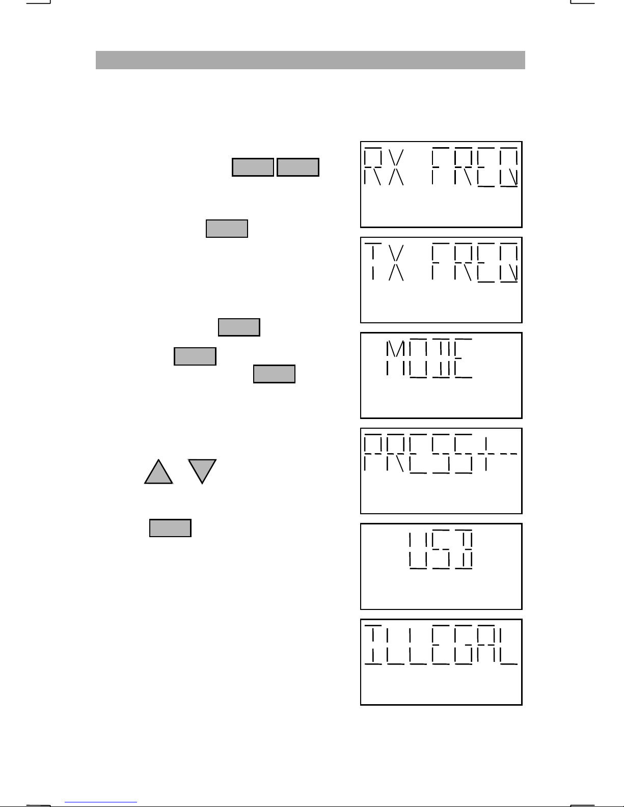
To enter a transmit frequency using the direct
frequency function press
Enter the receive frequency at the “RX FREQ”
prompt followed by . This frequency
ENT
must be in the range of 490.0 KHz to 29999.9
KHz.
At the “TX FREQ” prompt, enter the transmit
frequency followed by . If both the
transmit and receive frequency are the same
you can press . If the frequency being
ENT
entered is receive only, press
The transmit frequency must be in the range of
1600.0 KHz and 29999.9 KHz.
3 FNC
ENT
0
2182
After entering the transmit frequency, you will
need to select the “MODE” of operation.
Press the or key at the “PRESS+-”
prompt.
Press the key when the required mode
UP
ENT
DN
is displayed.
Under normal operations, USB is used for all
marine communicatio ns.
If the frequency entered (transmit or receive) is
outside the radio’s specified range, the display
will show “ILLEGAL” and return to normal
radio operations.
25
 Loading...