

SEA 1612C,1612WX,1612W Instruction And Maintenance Manual

T
T
r
t
;
T
;
;
;
t
r
T
t
I
;
!
----
_
-
5
-
-F
]-
!|ffi
-
E-
---_E
- -
r
E
h
a-
-
-
n
b
-
h
ffi
H
E
- r
r-
--I--
---
-
-
-
-
H
-l
r
-
-
-----
- n
-
-
ts
-
E
-
-
-
-
-
---A UNIT
OF DATAMARINE
INTERNATIONAL
I
NC.
sEA
1612C
r161
zVU
r161zWX
AUTOMATIC
ANTENNA
TUNER
INSTBUCTION
AND
MAINTENANCE
MANUAL
@ Copyright
1993, 1994
SEA Inc.
All
rights reseryed.
SEA Inc.
7030 2201h
sr, s.w.
Mountlake
Terrace,
Washington
98049
(425)
771-?182*
FAX:
(42s)
771-2650
MAN-1612C
Revision
D
July 2001
-G---
-
-
-
r-
I r -
--
- *
-
--
----F
- I
-T
E
-
-
-
- -
- r
*
p
-- r -
--I-!5t

IMPORTANT
NOTICE
TO
INSTALLERS
The
1ffi2D is
designed
to be
weatherproof
when
properly
installed.
Be
sure
all
fasteners
are tight
and
cable
entries
sealed.
No warranty
claims
will be
allowed
for
water
damage
to the
contents.
2.
2.1
2.2
TABLE
OF CONTENTS
1.
1.1
1.2
1.3
1.4
PAGE
GENERAL
INFORMATION...
.....1 . 1
Overall
Description
............
.......-.......1
-
1
Electrical
Configuration
..-.............1
-2
Mechanical
Configuration
...............1-2
Weather
Housing
.1..;1...........| ..............1
-4
SPECIFICATIONS AND
PARTS FURNISHED........,.....,....2. 1
Specif
ications............
......2-
1
Parts Furnished...............
.2-2
PR|NC|PLE OF OPERAT!ON...-...
.......,....3
-
1
Networks...........
..................3
-
1
Schematic
Diagrams
......3 - 1
Auto Tune Operation
...........3 - 1
Vswr Detector
..................3
-
3
Frequency Counter...
............3
-
3
Phase Detector
.................3
-
4
The Control
Computer...............
............3
-
4
Initialization
And Fireup
...............3
-4
lnformation
Flead
.............3
-
5
Information
Write......
,.....3
-
5
The Progr:am..............
.............3
-
5
INSTALLATION
PFOCEDURE
....4.
1
Mechanicat
Considerations.....
.............4
-
1
Electrical
Conslderations.,-......
.........-.4
-2
Electrical
Checkout..............
............4 - 3
TROUBLESHOOTING.......
....--.-..-5
-
1
COUPLER
WILL
NOT
TUNE
.
NO REI-AY
ACTION
.-.........5
-
1
RELAYS
OPERATE
BUT NO
TUNE
....5
-
2
C,OUPLER
TUNES
BUT
NO MEMORY
..5 - 3
TUNEB
WILL
NOT DEMAND
ruNE...............
.....,,5.3
SCHEMATIC
AND CIRCUIT
BOARD
LAYOUT
SEA
1612C COMPONENT
PARTS
LIST
3.
3.1
3.2
3.3
3.4
3.5
3.6
3,7
3.8
3.9
3.10
3.11
4.
4.1
4.2
4.3
5.
5.1
5.2
5.3
5.4
6.
7-
LISTOF
FIGURES
FIG.
#
FIGURE
MME
1.3
Outline and
Mounting
Dimensions.-...
3.1 Network
Configurations
.....,.....3-2
6,1
Antenna
Tuner Schematic
(ASY-1616-01)
6.2
Circuit
Board Layout
1.1
GENEHAL
INFORMATION
OVERALL DESCRIPTION
The
SEA
1612C
is a
fully
automatic
antenna
tuning
unit,
designed for
the
MF-HF spectrum
and
compatible
with a wide
variety
of
antenna
systems.
This
product
features an
advanced
microprocessor-based
tuning
algorithrn
which
allows
it
to
tune up
on
normal
voice
signals f rom
the
associated transmitter
and
also
includes
a
"learning"
algorithm
which
allows
the control
computer to remember
which
network
constants
are required
for
a
given
operating
frequency. The
memory feature
permits
the
antenna tuner,
once the
"learning"
operation
is
completed, to retune
a
given
frequency in approximately
20 milliseconds.
This
is
less
than the
time required
to say
"hello".
Antenna tuner
operation
is
completely
automatic
and requires
no
operator
intervention.
lf
the antenna system
is
altered
or
replaced,
the
tuner
will automatically
"relearn"
the
required networks.
During
the
learning
period,
operation
is somewhat
slower
and,
depending on the
particular
frequency/antenna
combination,
up
to
5 seconds
may be required to achieve
a
matched
condition. When the antenna
has
been
properly
malched,
the tuner signals this condition
by
pulling
a control
line
low. The
control signal may be
used to
operate
an
"all
tuned"
indicator
at the
operators'
T-Fl
position.
Such
an
indicator
is
provided
in
the
SEA
222,
SEA
322
and SEA 225
radiotelephones.
The SEA 1612C
also includes
a
"DEMAND
TUNE" function
and
a
'TUNE
LOCKOUT"
capability.
The
"DEMAND
TUNE"
function
allows the
user
to
force the
antenna
tuner to
retune
on
demand.
This
permits
"overwriting"
previously
stored
tuneup
information
when
desired.
The'TUNE
LOCKOUT"
feature
is
useful
when
two
or
more
transmitters
are
co-located,
or
when
it
is
desirable
to
inhibit the
AUTO
TUNE
function
for any reason.
1-1
E.G.: when
two
antennas
are
in
close
proximity,
it is
possible
that transmitting
on
one
antenna
may
cause
considerable
RF
to
be
coupled
into
the
adjacent
antenna.
This
can
cause
the
tuner
to
reset,
disturbing
the
operation
of the
radiotelephone.
In
such
cases,
the
"TUNE
LocKour''
feature
of
the sEA
1612c
can
be
used
to
prevent
the
SEA
1612C
from
entering
the
tune
mode
until
the radiotelephone
it is
associated
with is
actually
transmitting.
1
,2
ELECTRICAL
CONFIGURATION
The
sEA
1612c
matches
the
complex impedance
of the
antenna system
to
a nominal
50 ohms
by-'selecting."the:..,proper
network
from
a
possible
combination
of 64
values
of input
c,
32
values
of
output
c
and
s1z
values
of
series
L.
Network
configuration
is
automatically
determined during
the tune
cycle and
may
be
either
a Pl
network
or either
of
two
types
of L network.
whenever possible,
the
L
network
will
be
selected f
or
maximum
eff
iciency.
Tuneup
is
entirery
automatic
and
may
be
accomplished
on
voice
signals,
making
it
unnecessary
to
provide
a
"low
power
tune"
mode
in
the
trans
m itter.
1.3
The
various
RF
sensors
in the SEA
function
down
to
power
levels
of
feature makes
the SEA
1612C
equipment
such as
the SEA 225
circuitry
to
reduce
the output
power
hish
VSWR.
MECHANICAL
CON
FIGU
RATION
1612C are designed
to
10
to 20 watts. This
compatible
with radio
which is equipped with
level in
the
presence
of
All
of the circultry
of the SEA 1612C ls contained
on
printed
circuit
board PCB-1616-01.
This
printed
circuit board
is
mounted
on
an
aluminum shield
plate
with
six 6-32 stainless
steel screws. The
shield
plate
is held in
the
molded
weather
housing wlth four 10-24
stainless steel screws.
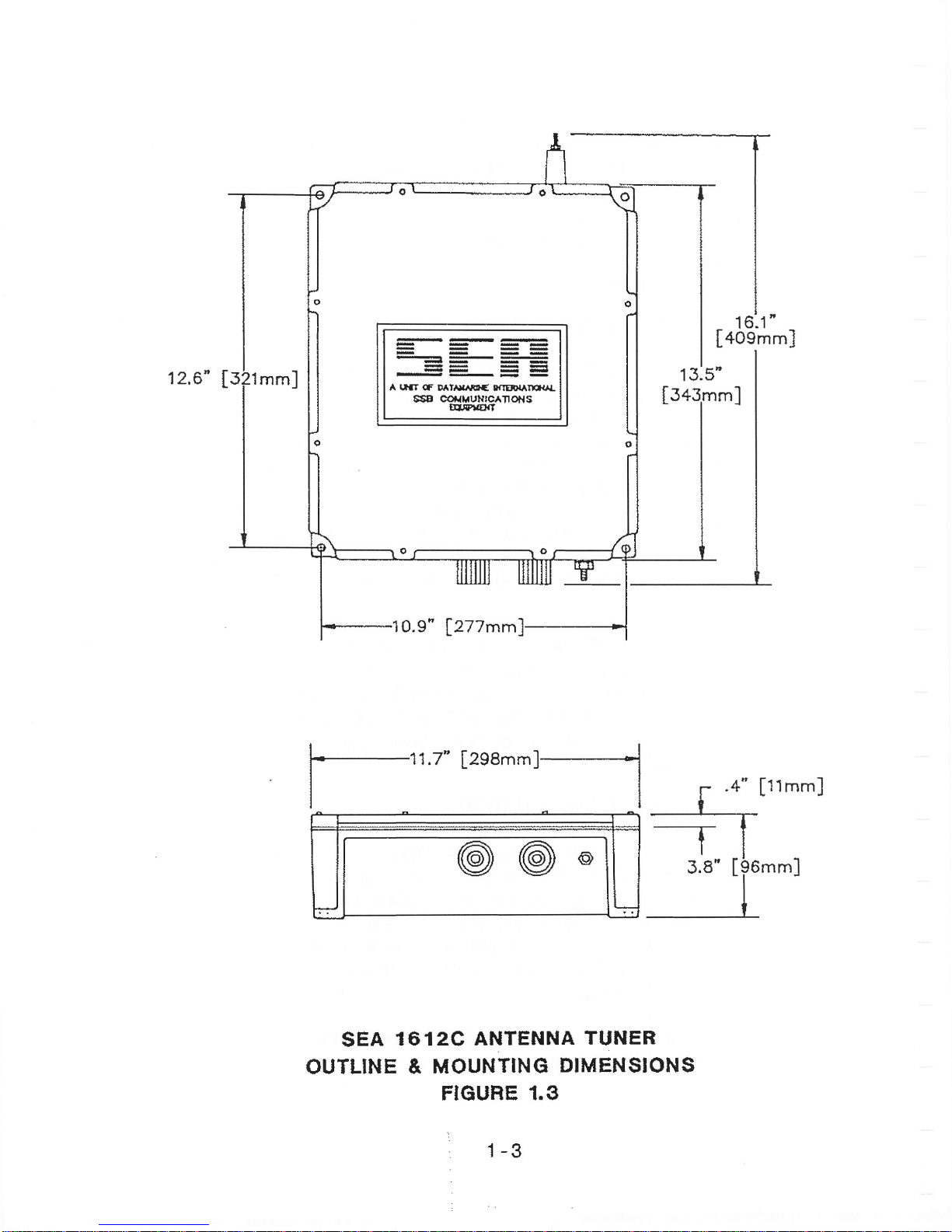
(Figure
1.3
shows the
outline
and
mounting
dimensions of the
molded
weather housing.)
The
printed
circuit board
is
solder-masked
which
helps to
prevent
corrosion and
moisture
problems.
1-2
12.6"
I
-
A
l,rt
f D t
'ra.\ftt(
tfIED{ IFN}L
6S8
@r{rtuNrc^TroNg
EIF|
T'
16:1'
[+osmm]
lztzmm
f-11;"
t2eemml--l
I
I
I
L_
[
"*"]
SEA
1612C
ANTENHA
TUNER
OUTLINE
& MOUNTING
DIMENSIONS
FIGURE
1,3
1-3
1.4
Both
the
so-239
RF
connector
and
the
six
pin
interface
connector
strip
are
mounted
on
the
printed
circuit
board
itself.
The
interface
connector
accepts wire
ends
directly,
eliminating
any
requirement
for
special
lugs
or
lugging
tools.
A PL-259
type
FIF
plug
must
be fitted
to the
coaxiar
feed line.
WEATHER
HOUSING
The
sEA
1612c
antenna
tuner is housed
in
a weatherproof
molded
case
designed
to withstand
the
environmental
conditions
encountered
aboard
ship
when
mounted
on
the
weather
decks.
The
internal
construction is
designed
to
withstand
the
shock
and
vibration
of marine
service.
corrosion-resistant
hardware
and
passivated
alroys are
employed
throughout.
stufflng
glands
for
the
RF and
Dc
cables are
provided
on
the
lower
edge
of
the
weather
housing,
along
with
a 1t4-ZO
stainless
steel
ground
stud.
The
antenna
connects to
the
ceramic
insulator
on the
top of
the
weather
housing.
I.5
SPECIAL
MODELS
OF THE
16I2C
The
l6l2C
is
avaitable
in
the following
two
optional
configurations:
thc l6lZW
and
thc
l6lZWX.
The l6l2W
is a i6t2C
with a gas
filled
spark
gap
tubc installed
on rhe
printed
circuit
board assembly.
This
part
will
shunt excessivcly
high voltages
to the
ground
plane (near
lightning
strikes)
to
prevent
darnage to thc RF sensors. The
l612WX
is
a l6l2W
with a RF
relay
assembly that
shorts
the
antenna output
connector
to
ground
when
then
power
to the
couplcr
is
switched
OFF. Please contact
the
factory
for additional
information.
1-4
2.
SPECIFICATIONS
AND PARTS
FURNISHED
2.1
SPECIFICATIONS
Frequency
Range
1.6 to
30.0 MHz
RF
Power
Capability
150 watts Peak
Envelope Power
(PEP)
Input
lmpedance
50 ohms
VSWR
<2:1
Power Requirements
13.6
VDC
negative
ground
Operating Current
2
Amps max.
Tuning
Time
"Learn
Mode",
typically
less
than 5
seconds
"Educated
Mode", approximately
20
milliseconds
Recommended 23-75
ft.
(7-23
meters) 1.6-30
MHz
Antenna
Length I ft.
(2.7
meters) whip 3-30
MHz
Mounting
Any
position
Environmental Temp.
Range
-30"C
to +60oG
Size
in:
15 X 12 X
3.9
mm:
381
X
304.8
X
99
Weight
10
1bs./4.5
kgs.
Case Construction
Molded
Weatherproof
Control
Cable
No.
20 Gauge, 3 to
5 conductors,
shielded
(not
supplied)
2-1

2.2
PARTS
FURNISHED
1.
Antenna
Tuner
with
Cover
and
Bushings
2.
Instruction
Manual
2-2
3.
3.1
PRINCIPLE
OF
OPERATION
NETWORKS
Figure
3.1 shows
the schematic
diagram for
the two basic
network
configurations.
Note
that the
nln
network
as viewed
from
the
generator
may be
configured
as either
"C
in" or"C
out",
whichever
is
required
by
the
load.
In
either case, the
end
of the
network containing
the shunt C
element will be the
HIGHER
impedance
end of the network.
SCHEMATIC
DIAGHAMS
Figure
6.1
is
the schematic diagram
of the antenna tuner. RF
input is
applied
to
UHF fitting J1, 13.6 VDC is
connected to
the terminals marked
GND
and + on
P1
(Pins
1 and 2
respectively),
and an
appropriate
antenna
and
ground
system
are connected to feedthrough
insulator and
stainless
steel
stud
respectively.
The
"TND"
flag line
(Pin
4 on P1)
is
connected to the remote indicator
device
used. When
the SEA
16'1
2C is
used with the
SEA
222,
SEA 322 or
SEA 225
radiotelephone,
the flag line
is
connected
to the
"TND"
line
on
the
radio's
rear
panel
connector.
AUTO TUNE OPERATION
When RF
power
is
applied
to
the SEA
1612C
it is first
passed
through an
array of detectors
which
determine the
frequency,
load
VSWR
and the reactance sign.
Forward
power
is
continuously
monitored,
since
the
control
computer
requires
an
indication
of
both forward
and
reflected
power
in
order
to
allow
tuning
to
proceed.
ln
practice,
the
forward
power
detector is
used
by the
computer
as
a
truth
check
to insure
that
the
measurements made
are
indeed
a result
of
applied
RF
and
not
spurious
levels
from
the
data
conversion
system.
Tuneup
will
ONLY
proceed
when
sufficient
forward
power
is
present
to
provide
this
truth
check.
After
passing
through
the
detector
system,
the
FIF
is
applied
to the
tuner
array.
This
consists
of 6 capacitors
in
shunt
on the
input
arm
of
the
network,
arranged
in
binary
increments,
I inductors
in
the
series
arm,
arranged
in
binary
increments,
and
5
more
capacitors
in
shunt
on the
output
arm,
also
arranged
in
binary
increments.
Relays are
provided
in
conjunctlon
with
each
3.2
e.)
\r.
(J
3-1
3.4
lumped
constant
which
allow
removal
or
entry
as
desired.
Thus,
it is
possible
through
the
manipulation
of
26 rerays
to
build
a
network
having
64
values
of input
shunt
c, 32
values
of
output
shunt
C,
and
up
to
512
values
of
series
L.
VSWR
DETECTOR
Current
transformer
T1
and voltage
transformer TZ,
in
conjunction
with
termination resistors
R1
and
RS
make
up a
dual
directional
coupler.
This directional
coupler
is inserted
in
the
50
ohm
transmission
line between
the input
connector,
J1,
and
the
tuning network.
A
sample of FORWAFID
power
appears
across
termination
Rl,
while
d,.simple
of,'REFLECTED
power
appears
across
termination
R5.
The FORWARD
and
REFLECTED
power
RF
samples
from
the
directional coupler
are detected
by diodes
CR1
and CR3.
H/C filter networks
are
provided
on
both
the FORWAHD
power
and
REFLECTED power
signals
and
both
are clamped
to the +5 Volt rail
through
diodes CRZ
and
CR4 to
prevent
overdriving
the
A/D
converter
inputs
of CPU
chip, U5.
With
voltages
representing
both FORWARD
and
REFLECTED
power
available
to the
CPU,
it
is
possible
to compute
the
VSWR
continuously
during
the tuning
process.
FREQJENCY
CCTJN]ER
The
memory
storage
system in
the SEA
1612C
is based on the
fact that the control
computer
senses what
frequency is in
use.
This
is
accomplished
by applying
a
prescaled
sample
of
the
RF
signal to
the
the
CPU timer
input.
The
prescaler
consists of U1A,
U2
and U3.
A sample
of the RF
signal is
applied through a biased clamping
network
consisting
of
CRg,
CR10, R17, R18, R19
and R20,
to the input
of CMOS
schmitt
trigger U1A. The
shaped
output
signal is
then divided
by
2048 through
cascaded
counters
U2 and
U3.
The
output from the
counter
train
also serves as an interrupt
generator
for the CPU,
acting as
an
'FlF
present"
indicator.
3.5
3-3
 Loading...