

SEA 1110,1111 Important Safety Instructions Manual
GENERAL
This swing gate operator system is designed to control vehicular traffic only. This operator system must never be used as a
means to control pedestrian or bicycle traffic. Serious injury or death to pedestrians may result if this operator is used in this
manner.
If pedestrian traffic is expected to be near or needs to walk through, a separate pedestrian lane or pedestrian gate is required.
Never allow pedestrians or pets to pass through this gate system.
Reversing devices are required to prevent the gate from closing on vehicular traffic. It is appropriate to the gate design and
gate application.
This vehicular gate operator is intended to be a part of a total gate operating system. It is the responsibility of the purchaser
and installer to ensure the total system is sale for its intended use.
BEFORE INSTALLATION
Check to be sure this is the proper gate operator system for the intended use.
Be sure the gate has been properly installed, gate posts are plumb and gate leafs operate freely. Make any necessary repairs
to the gate before installing this equipment.
A separate pedestrian gate is required if pedestrian traffic is expected to be near or if pedestrians need to walk through.
Furthertnore, photo-eyes and/or reversing edges need to be added to help prevent injuries.
Only qualified personnel should install this equipment. Failure to meet this requirement could cause severe injury and/or
death, for which the manufacturer/distributor can not be held responsible.
Review this installation manual and the gate operator system prior to installation, maintenance and service.
DURING INSTALLATION
Check that the main power supply circuit breakers are separate, intended solely for this equipment and rated for 15 AMPS.
Visually check that the circuit breakers are in the "OFF" position and mark the circuit breakers "USED" prior to installation.
Place all access devices a minimum of 10 feet away from the gate. Install access devices in a way the user can see, but not
touch the operator and/or gate while operating the controls. Install controls so that unauthorized use is prevented.
Reversing devices such as loops, photo-eyes, and/or reversing edges are required to prevent the gate from closing on
vehicular traffic and/or help prevent injuries to pedestrians. It is appropriate to the gate design and application.
Always disconnect power supply when servicing this equipment.
If this gate operator system includes a battery backup, the battery backup system needs to be disconnected first, prior to
disconnecting main power supply during installation, maintenance and servicing procedures.
AFTER INSTALLATION
Check to make sure the gate operator system is working properly, that the open and close force are properly adjusted, that the
piston does not bottom out in either direction, that breather screws have been removed, that the positive stops used are
sufficient for stopping the gate properly, and that all pinch points and potential entrapment areas are reduced.
Check and test all reversing devices for proper operation.
The installer of this system needs to read and understand the operation of this gate operator system, its safety features and
know how to place the gate in manual operation.
Show end user the proper operation of this gate system. Explain how the reversing system works. Show user how to place
gate operator system in manual operation.
This manual is to be left with the end user.
IMPORTANT SAFETY INSTRUCTIONS
SAVE THESE INSTRUCTIONS
READ AND FOLLOW ALL INSTRUCTIONS
Rev. 02 - 07/2008
Pag. 1/10
1110, 1111 (Lepus Series)
9001
Code 67410320UL
SEA USA Inc.
10850 N.W. 21st unit 160 DORAL MIAMI
Florida (FL) 33172
Phone:++1-305.594.1151 Fax: ++1-305.594.7325
Toll Free: 800.689.4716
www.sea-usa.com
sales@sea-usa.com
International registered trademark n. 2.777.971
GROUNDING
Good grounding and proper surge suppression are an integral part of proper installation for a gate operator system. One or all
of the following may require surge suppressors: high voltage power lines, low voltage power lines, telephone lines, data lines,
low voltage control lines and loops. How much surge suppression is required depends upon how susceptible the area is to
lightning and power surges. Regardless, good grounding is essential. To realize maximum protection, proper grounding and
proper surge suppression is absolutely necessary.
If the circuit breaker box is located close to the gate operator system, for example, in a guard house, then the ground from that
circuit can be used to ground the gate operator system. Eliminate all 90° bends in ground wires and keep a minimum of three
feet between the surge suppressor and the equipment being protected.
If the power source or circuit breaker box is not located close to the gate operator system an Isolated Ground Zone (IGZ) needs
to be created. An IGZ can also be created if the circuit breaker box is located close by the gate operator system. An IGZ is an
imaginary circle drawn around the gate operator system. The gate operator system not only includes the gate operators and
control panel, but all of the accessories and devices associated with it at that controlled entry point. This includes loop
detectors, card readers, digital entries, telephone entries, any device that has a ground or requires a ground and ali of the surge
suppressors. The ground bus is a common ground point calied a Single Point Ground (SPG). It is used to bond all the
equipment and device grounds in the IGZ together. The SPG is very important because it helps eliminate different ground
potentials that can be present on the equipment. In such cases, equipment damage occurs even with surge suppressors.
Do not use or connect the ground wire coming from the circuit breaker box. By using an Isolated Ground Zone, you are
separating the gate operator system from the house or building ground. This eliminates ground potentials. It is recommended
that the ground bus be located in a separate NEMA type enclosure. All grounds will be tied to this ground bus. Some points to
remember:
Keep all ground wires as straight as possible. Do not have any sharp 90° bends. Have a minimum of 3 feet of wire between the
surge suppressor and the equipment being protected.
Equipment ground wire should be a minimum of 12 AWG. The main ground wire from the bus bar to the ground rod shouid be
an 8 or 6 AWG copper wire. Ground rod should be a minimum of 10 feet in length, longer depending on local soil conditions.
For more information regarding good grounding practices check: National Electric Code art. 250; IEEE Emerald Book,
standard 100; International Association of Electric Inspectors.
SAVE THESE INSTRUCTIONS
READ AND FOLLOW ALL INSTRUCTIONS
IMPORTANT SAFETY INSTRUCTIONS
Pag. 2/10
Code 67410320UL
1110, 1111 (Lepus Series)
9001
SEA USA Inc.
10850 N.W. 21st unit 160 DORAL MIAMI
Florida (FL) 33172
Phone:++1-305.594.1151 Fax: ++1-305.594.7325
Toll Free: 800.689.4716
www.sea-usa.com
sales@sea-usa.com
International registered trademark n. 2.777.971
Rev. 02 - 07/2008
WIRING AND MOUNTING
This system requires a separate power supply circuit, intended solely for this equipment and rated for 15 AMPS. Visually check
that the circuit breakers are in the "OFF" position and mark the circuit breakers "USED" prior to installation.
Permanent wiring must be used and installed to the operator as required by local electrical codes. It is recommended that this
be performed by a licensed electrician. Prior to doing any type of wiring, it is highly recommended that you check with your local
building department to be sure that all wiring to the operator and various accessories complies with local building code
requirements. It is recommended that you color code all wiring. Local building codes will take precedence.
Distance for low voltage control wires, i.e., open input, single leaf open input and stop input, can run up to 3000 feet with 18 AWG
wire.
All low voltage control and communication wiring must be separated by a minimum of 1 foot from high voltage power wiring and
in a separate conduit.
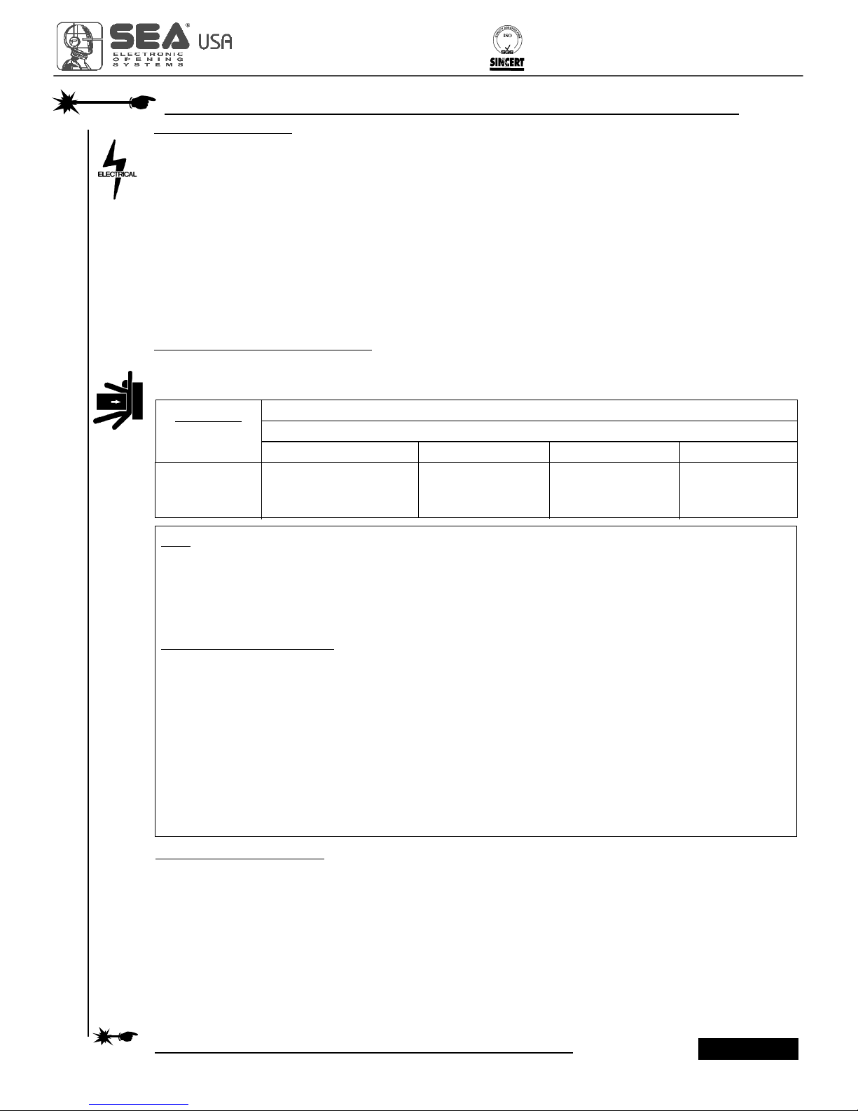
GENERAL ENTRAPMENT PROVISIONS
A vehicular gate operator must be installed with at least one independent primary and one independent secondary
means to protect against entrapment (see Table A):
CLASS OF GATE OPERATORS
RESIDENTIAL VEHICULAR GATE OPERATOR - CLASS I - A vehicular gate operator (or system) intended for use in a home
of one-to four single family dwelling,or a garage or parking area associated therewith.
COMMERCIAL/GENERAL ACCESS VEHICULAR GATE OPERATOR - CLASS II - A vehicular gate operator (or system)
intended for use in a commercial location or building such as multi-family housing unit (five or more single family units), hotel,
garage, retail store, or other building servicing the general public.
INDUSTRIAL/LIMITED ACCESS VEHICULAR GATE OPERATOR - CLASS III - A vehicular gate operator (or system)
intended for use in a industrial location or building such as a factory or loading dock area or other locations not intended to
service the general public.
Note: The same type of device shall not be utilized for both the primary and secondary
entrapment protection means. Use o a single device to cover both the opening and closing
directions is in accordance with the requirement; however, a single device is not required to
cover both directions. A combination of one Type B1 for one direction and one Type B2 for
the other direction is the equivalent of one device for the purpose of complying with the
requirements of either the primay or secondary entrapment protection means.
Entrapment protection types
Type A: Inherent entrapment sensing system.
Type B1: Provision for connection of a non contact sensor (photoelectric or equivalent).
Type B2: Provision for connection of a contact sensor (edge device or equivalent).
Type C: Inherent adjustable clutch or pressure relief device.
Type D: Provision for connection of an actuating device requiring continuous pressure to maintain opening
or closing motion of the gate.
Type E: An inherent audio alarm.
GATE OPERATOR CATEGORY
Horizontal slide, vertical life and vertical pivot
Swing and vertical barrier (arm)
Secondary type
Primary type
Secondary type
B1,B2 or D
A,B1,B2,D or E
A,B1,B2,D or E
A or C
A,B1 or C
A,B1,C or D
A,B1,C or D
A,B1,C,D or E
A,B1,C,D or E
TABLE A
Usage Class
Primary type
Vehicular I and II
Vehicular III
Vehicular IV
A
A,B1 or B2
A,B1,B2 or D
READ AND FOLLOW ALL INSTRUCTIONS
Pag. 3/10
SAVE THESE INSTRUCTIONS
IMPORTANT SAFETY INSTRUCTIONS
Code 67410320UL
1110, 1111 (Lepus Series)
9001
SEA USA Inc.
10850 N.W. 21st unit 160 DORAL MIAMI
Florida (FL) 33172
Phone:++1-305.594.1151 Fax: ++1-305.594.7325
Toll Free: 800.689.4716
www.sea-usa.com
sales@sea-usa.com
International registered trademark n. 2.777.971
Rev. 02 - 07/2008
 Loading...