

Page 1

WWW.SCOTT-SPORTS.COM
WWW.SCOTT-SPORTS. COM
SCOTT Spor ts SA
Route du Crochet 17, CH–1762 Givisiez
Phone: +41 26 460 16 16 | Fax: +41 26 460 16 00
Email: postmaster@scott-sports.com
All rights r eserved ©201 5 SCOTT Sports S A
Distribution:
SSG (Europ e) Distribution Ce nter SA, P.E.D. Zon e C1, Rue du Ki ell 60, 6790 Aub ange, Belgi um
v5.1/030 82015
SCOT T GENIUS
USER MANUAL 2016
Page 2

WWW.SCOT T-SPORTS.CO M
ENGLISHENGLISH
Genius Concept . . . . . . . . . . . . . . . . . . . . . . . . . . . . . . . . . . 04
Geometry/Technical Data Genius 70 0 . . . . . . . . . . . . . . . . . . . . . 05
Geometry/Technical Data Genius 900 / 700 Plus . . . . . . . . . . . . . . 06
TC Shock Technology/Twinloc Levers . . . . . . . . . . . . . . . . . . . . . .07
Assembly of the Remote Cable . . . . . . . . . . . . . . . . . . . . . . . . . . 10
FOX Nude Shock and Twinloc Remote Control Lever . . . . . . . . . . . . . 11
Basic Set- Up of the Twinloc Remote Control of FOX Nude Shock . . . . . . 12
Basic Set- Up of the Twinloc Remote Control of Fox CTD Shock . . . . . . . 14
Recommended Tools for the Shock Se t-Up . . . . . . . . . . . . . . . . . . . 14
Set-Up Genius With FOX Nude Or FOX CTD Shock . . . . . . . . . . . . . . 15
SAG . . . . . . . . . . . . . . . . . . . . . . . . . . . . . . . . . . . . . . . . . . 16
Set-Up of Rebound FOX Nude Or FOX CTD Shock . . . . . . . . . . . . . . .16
Set-Up of Other Shock Models . . . . . . . . . . . . . . . . . . . . . . . . . . 18
Headset Options . . . . . . . . . . . . . . . . . . . . . . . . . . . . . . . . . . .18
Bottom Bracket (BB) on Genius . . . . . . . . . . . . . . . . . . . . . . . . . .19
Adjustable BB Height . . . . . . . . . . . . . . . . . . . . . . . . . . . . . . . 20
Front Derailleur (FD) Mounting Details. . . . . . . . . . . . . . . . . . . . . .21
Chainguide . . . . . . . . . . . . . . . . . . . . . . . . . . . . . . . . . . . . . .22
Genius Cable Routing . . . . . . . . . . . . . . . . . . . . . . . . . . . . . . . .23
Adjustment of Seatpost-Height . . . . . . . . . . . . . . . . . . . . . . . . . .27
Replaceable Dropout . . . . . . . . . . . . . . . . . . . . . . . . . . . . . . . .28
Rear Disc Brake Mount . . . . . . . . . . . . . . . . . . . . . . . . . . . . . . .28
Front Fork Set- Up/Change of Front Fork . . . . . . . . . . . . . . . . . . . .29
Pivot Maintenance . . . . . . . . . . . . . . . . . . . . . . . . . . . . . . . . . .29
Warranty . . . . . . . . . . . . . . . . . . . . . . . . . . . . . . . . . . . . . . 30
•
CONTENTS
The Geniu s should be ad justed exactly to the current rider for
reaching maximum safety a nd fun while riding.
All adjustm ents should be done at your local SC OTT dealer or
following this ma nual’s instructions.
In order to avoid technical proble ms or any harm please contact
in case of doubts your authorized SCOT T d ea le r.
03 |
2016 BIKE USE R MANUAL | GENIUSGENIUS | 2016 BIKE USER MANUAL
| 02
Page 3
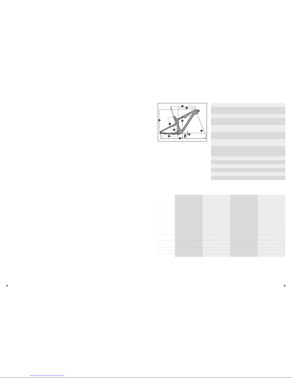
S S M M L L XL XL
LOW BB SETTI NG HIGH BB SE TTING LOW BB SE TTING HIG H BB SETTING L OW BB SETTING H IGH BB SET TING LOW BB SET TING HIGH BB S ETTING
A
HEAD TUBE
ANGLE
67.9 ° 68.4 ° 67. 9 ° 68 .4 ° 67.9 ° 68.4 ° 67. 9 ° 68 .4 °
B
HEAD TUBE
LENGTH
100.0 mm 3.9 in 100.0 mm 3. 9 in 110.0 mm 4 .3 in 110.0 mm 4 .3 in 120.0 mm 4.7 in 120.0 mm 4.7 in 135. 0 mm 5. 3 in 135 .0 mm 5 .3 in
C
TOP TUB E
HORIZONTAL
569.9 mm 2 2.4 in 568 .6 mm 22.4 in 5 99.9 mm 23. 6 in 598.6 m m 23.6 in 624 .9 mm 24.6 in 623.6 mm 24. 6 in 649.9 mm 25 .6 in 648.6 m m 25.5 in
D
STANDOVER
HEIGHT
773.1 mm 30.4 in 77 5.9 mm 30. 5 in 774. 6 mm 30.5 in 777.6 mm 30.6 in 80 7.0 mm 31. 8 in 810.4 mm 31 .9 in 809. 0 mm 31.9 in 8 12.4 mm 32.0 in
E BB OF FSET
-11.6 mm -0 .5 in -6 .1 mm -0 .2 in - 11.6 mm -0.5 i n -6.1 m m -0. 2 in -11 .6 mm - 0.5 in -6.1 mm -0. 2 in -11 .6 mm - 0.5 in - 6.1 mm - 0.2 in
F BB HEIGHT
344.9 m m 13.6 in 350.4 mm 13. 8 in 344 .9 mm 13 .6 in 350.4 mm 13.8 in 3 44.9 mm 13.6 in 350.4 mm 13.8 in 3 44.9 mm 13.6 in 3 50.4 mm 13.8 in
G WHEEL BASE
1’122 .7 mm 44.2 in 1’12 1.8 mm 44. 2 in 1’153.8 mm 45.4 in 1’152.9 m m 45.4 in 1’179.9 mm 46.5 in 1’179.0 mm 46.4 in 1 ’206.6 mm 47.5 i n 1’205.7 mm 47. 5 in
H
BB CENTER
TO TOPTU BE
CENTER
I
BB CENTER
TO TOP OF
SEATTUBE
415.0 mm 16. 3 in 415.0 mm 16.3 in 440.0 mm 17.3 in 440.0 mm 17.3 in 475.0 mm 18.7 in 475.0 m m 18 .7 in 510.0 mm 20 .1 in 510.0 mm 20.1 i n
J SE AT AN GLE
74.0 ° 74. 5 ° 74. 0 ° 74. 5 ° 74. 0 ° 74. 5 ° 74. 0 ° 74. 5 °
K CH AIN STAY
439.0 mm 17.3 in 439.0 mm 17.3 in 439.0 mm 17.3 in 439.0 mm 17.3 in 439.0 mm 17.3 in 439.0 mm 17.3 in 439.0 mm 17.3 in 439.0 mm 17.3 in
L R EACH
401.4 mm 15. 8 in 406.1 mm 16.0 in 428.7 mm 16.9 in 43 3.4 mm 1 7.1 in 45 1.1 mm 17. 8 in 455 .7 mm 17.9 i n 472 .1 mm 18.6 i n 476 .7 mm 18.8 in
M STACK
588. 8 mm 23.2 in 585.5 mm 23.1 in 59 8.1 mm 23.5 in 59 4.7 mm 23.4 i n 607. 3 mm 23.9 in 603. 9 mm 23.8 in 621.2 mm 24.5 in 6 17.7 m m 24.3 in
N STEM LENGTH
60.0 mm 2 .4 in 60.0 mm 2.4 in 70.0 mm 2.8 in 70.0 mm 2 .8 in 80.0 mm 3.1 in 80.0 mm 3.1 in 90.0 mm 3. 5 in 90.0 mm 3.5 in
ENGLISHENGLISH
•
GEOMETRY/TECHNICAL DATA GENIUS 700
•
GENIUS CONCEPT
The new Genius is the result of 2 yea rs of research and development for one of the lightest
trail/marathon bike frame set available on the market, hitting the scale at be low 2300g (5 lbs)
including the frame, FOX Nude /CTD shock a nd the uniqu e TWINLOC remote control.
SCOT T’s focus was not only on light weight but also o n a durable and stiff fra me with an
innovative suspension technology in combination with an optimized kinematic s of the rear
swingarm.
The combination of an optimized kinematics with an extraordinary suspe nsion technology
closes the gap between superlight dua l suspension race bikes (e.g. SC OTT S park) and the
new generation of all-mountain bikes (e.g. S COTT Geniu s LT ).
Genius was d esigned for riders looking for a dual su spended trail and marathon bike offe ring
a maximum rear wheel travel of 15 0mm (700) / 130 mm (900 / 700 P lu s).
SCOT T does n ot see frame a nd rear shock as single comp onents which are assembled
together on a bike, but as a conce pt with all these components working together and
offering an outrageo us functio n by matching per fectly.
The Geniu s Concept is ba sed on a multi- pivot technology.
The dampin g perform ance was improved in comparison to the already famous “old” Genius,
and with reworking also the kinematics we were able to rea ch a better prog ression in the end
of the stroke/travel of the swingarm.
The SCOT T system , using the Nude shock, na med TC (Traction Control) will allow you
to reduce by remote control the rear wheel travel from 150 mm (700) / 130mm (900 /
700Plus) to 100mm ( 700) / 90mm (90 0 / 700 Plus) includin g a more progressive spring
rate but still offering a suppl e break away. In addition the SAG is reduced and the geometry
gets steeper.
Some models of Genius use also the FOX CTD sh ock which of fers instead of the Traction
Mode a Platform (Ride Mo de) in between Clim b Mode and D escent Mod e
No power will be lost and an optimum power transfe r is guarantee d as the swingarm, in
contrary to lo cked or automatic -locking systems, can follow the trail sur face and will offer
perfec t traction and higher spe ed while standing on the pedals.
Trav el 150/ 100/0 mm
Suspension
Ratio
2.72
Piston stroke 55mm
Shock length
(Eye to Eye)
200mm
Hardware
Mainframe
22. 2mm x 6mm
Hardware
Swingarm
22. 2mm x 6mm
Seatpost
diameter
31.6mm
Headset
semi integ r. for tapered 1 1 /8-1.5 (44/5 4.9mm
Inner di ameter of fra me) or with 1 1/8 s traight
(44 .0m m)
Fork travel 150mm
Fork length 544mm
BB housing BB PF 92
Front derailleur Shiman o E-Type/SRAM S3 dire ct mount
Bearings 2 x I GUS / 6 x 680 2 (24 x 15 x 5)
Max Tire Wid th 57mm/2 .25”
05 |
2016 BIKE USE R MANUAL | GENIUSGENIUS | 2016 BIKE USER MANUAL
| 04
Page 4
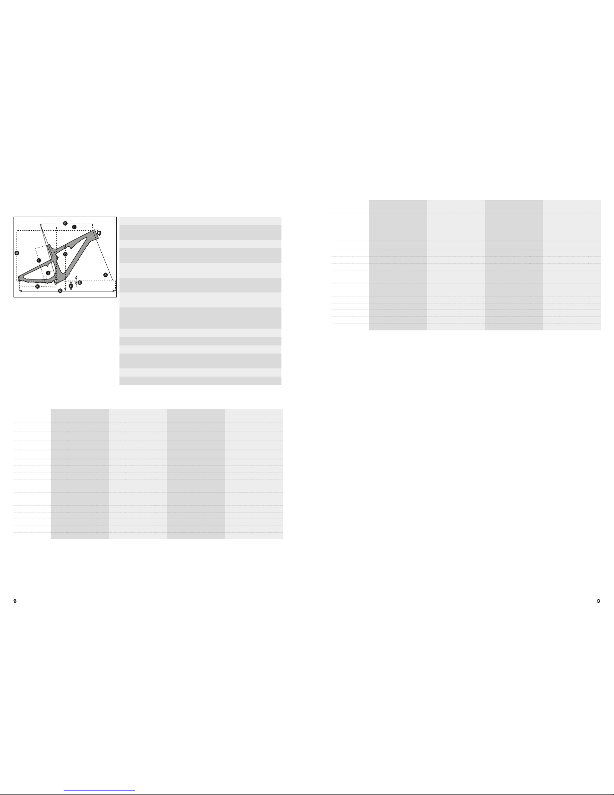
GENIU S 900
S S M M L L XL XL
LOW BB SETTI NG HIGH BB SE TTING LOW BB SE TTING HIG H BB SETTING L OW BB SETTING H IGH BB SET TING LOW BB SET TING HIGH BB S ETTING
A
HEAD TUBE
ANGLE
68.9 ° 69.4 ° 68.9 ° 69.4 ° 69.0 ° 69.4 ° 69.0 ° 69.4 °
B
HEAD TUBE
LENGTH
100.0 mm 3.9 in 100.0 mm 3. 9 in 100.0 mm 3.9 in 100.0 mm 3 .9 in 110.0 mm 4 .3 in 110.0 mm 4.3 in 12 0.0 mm 4.7 in 120.0 mm 4.7 in
C
TOP TUB E
HORIZONTAL
570.3 mm 22.5 in 5 69.0 mm 22.4 i n 600.3 mm 23.6 in 598.9 mm 2 3.6 in 625 .2 mm 24.6 in 623.8 mm 24.6 in 650.2 mm 25.6 in 64 8.8 mm 25. 5 in
D
STANDOVER
HEIGHT
770.4 mm 30.3 in 772 .8 mm 30.4 in 7 72.8 mm 30. 4 in 775.5 m m 30.5 in 803.0 m m 31.6 in 80 6.1 mm 31.7 in 800.6 mm 31.5 in 803.8 mm 31.6 in
E BB OF FSET
-34.5 mm -1.4 in -2 9.1 mm -1.1 in -3 4.5 mm -1 .4 in -29.0 mm -1.1 in -34. 0 mm -1.3 in -28.5 mm -1.1 in -3 4.0 mm -1.3 i n -28.4 m m - 1.1 in
F BB HEIGHT
335.5 m m 13 .2 in 340.9 mm 13.4 in 335.5 mm 13.2 in 341 .0 mm 13.4 in 3 36.0 mm 13.2 in 341. 5 mm 13.4 in 336.0 mm 13.2 in 341. 6 mm 13.4 in
G WHEEL BASE
1’112 .2 mm 43.8 i n 1’111.8 mm 4 3.8 in 1’142.2 m m 45.0 in 1’1 41.8 mm 45.0 in 1’ 168.0 mm 46. 0 in 1’ 167. 6 mm 46.0 in 1 ’193.9 mm 47. 0 in 1’193 .5 mm 4 7.0 in
H
BB CENTER
TO TOPTU BE
CENTER
I
BB CENTER
TO TOP OF
SEATTUBE
415.0 mm 16. 3 in 415.0 mm 16.3 in 440.0 mm 1 7.3 i n 440.0 mm 17.3 i n 475.0 mm 18.7 in 475.0 mm 18.7 in 510.0 mm 20.1 in 510.0 mm 20.1 in
J SE AT AN GLE
73.9 ° 74 .4 ° 73. 9 ° 74.4 ° 74.0 ° 74.4 ° 74.0 ° 74.4 °
K CH AIN STAY
450.0 mm 1 7.7 in 449.0 m m 1 7.7 in 450.0 mm 17.7 in 449 .0 mm 17.7 in 449 .9 mm 17.7 in 44 8.9 mm 17.7 i n 449.9 mm 17.7 i n 448.9 mm 17.7 in
L R EACH
394.2 mm 15.5 in 399. 2 mm 1 5.7 in 424.2 mm 16.7 in 429 .1 mm 16.9 in 4 47.1 m m 1 7.6 in 451. 8 mm 17. 8 in 469.4 mm 18.5 in 474 .1 mm 18.7 i n
M STACK
770.4 mm 30. 3 in 772. 8 mm 30.4 in 77 2.8 mm 30.4 in 775.5 mm 30 .5 in 80 3.0 mm 31 .6 in 806.1 mm 31. 7 in 800.6 mm 31 .5 in 803 .8 mm 3 1.6 in
N STEM LENGTH
60.0 mm 2 .4 in 60.0 mm 2.4 in 70.0 mm 2.8 in 70.0 mm 2 .8 in 80.0 mm 3.1 in 80.0 mm 3.1 in 90.0 mm 3. 5 in 90.0 mm 3.5 in
GENI US 700
PLUS
S S M M L L XL XL
LOW BB SETTI NG HIGH BB SE TTING LOW BB SE TTING HIG H BB SETTING L OW BB SETTING H IGH BB SET TING LOW BB SET TING HIGH BB S ETTING
A
HEAD TUBE
ANGLE
67.5 ° 68.0 ° 67. 5 ° 68 .0 ° 67.5 ° 68.0 ° 67. 5 ° 68. 0 °
B
HEAD TUBE
LENGTH
100.0 mm 3.9 in 100.0 mm 3. 9 in 100.0 mm 3.9 in 100.0 mm 3 .9 in 110.0 mm 4 .3 in 110.0 mm 4.3 in 12 0.0 mm 4.7 in 120.0 mm 4.7 in
C
TOP TUB E
HORIZONTAL
570.0 mm 22 .4 in 570.0 mm 22 .4 in 600.0 mm 23.6 in 600.0 mm 23 .6 in 625.0 mm 24.6 in 625.0 mm 24 .6 in 650.0 mm 25 .6 in 650.0 mm 25. 6 in
D
STANDOVER
HEIGHT
819.0 mm 32.2 in 8 22.0 mm 32. 4 in 823.0 mm 32.4 in 826 .0 mm 32.5 in 8 43.0 mm 33. 2 in 84 6.0 mm 33.3 in 8 65.0 mm 34.1 in 868 .0 mm 3 4.2 in
E BB OF FSET
-30.0 mm -1.2 in -2 5.0 mm -1. 0 in -30.0 mm -1.2 in -25 .0 mm -1.0 i n -30.0 mm -1.2 in -25 .0 mm -1.0 in -30.0 mm -1. 2 in -25. 0 mm -1.0 in
F BB HEIGHT
335.0 mm 13.2 in 340.0 mm 1 3.4 in 3 35.0 mm 13.2 in 3 40.0 mm 13 .4 in 3 35.0 mm 13.2 in 3 40.0 mm 13 .4 in 3 35.0 mm 13.2 in 34 0.0 mm 13 .4 in
G WHEEL BASE
1’135.0 mm 44.7 in 1’134 .0 mm 4 4.6 in 1’165.0 mm 45. 9 in 1 ’164. 0 mm 45 .8 in 1’191.0 mm 46 .9 in 1’190.0 mm 4 6.9 in 1’2 71.0 mm 50. 0 in 1’270.0 mm 50.0 in
H
BB CENTER
TO TOPTU BE
CENTER
336.0 mm 13.2 in 336.0 mm 13.2 in 345.0 mm 13.6 in 3 45.0 mm 13.6 in 3 78.0 mm 14.9 in 37 8.0 mm 1 4.9 in 409. 0 mm 1 6.1 in 409.0 mm 16.1 in
I
BB CENTER
TO TOP OF
SEATTUBE
415.0 mm 16. 3 in 415.0 mm 16.3 in 440.0 mm 1 7.3 i n 440.0 mm 17.3 i n 475.0 mm 18.7 in 475.0 mm 18.7 in 510.0 mm 20.1 in 510.0 mm 20.1 in
J SE AT AN GLE
73.9 ° 74 .4 ° 73. 9 ° 74.4 ° 73.9 ° 74 .4 ° 73. 9 ° 74.4 °
K CH AIN STAY
445.0 mm 1 7.5 i n 445.0 mm 1 7.5 in 445.0 mm 17. 5 in 445.0 mm 17. 5 in 445.0 mm 1 7.5 i n 445.0 mm 1 7.5 i n 445.0 mm 1 7.5 i n 445.0 mm 1 7.5 in
L R EACH
395.0 mm 15.6 in 399.0 mm 15.7 in 425.0 mm 16.7 in 429.0 mm 1 6.9 in 44 8.0 mm 1 7.6 i n 452.0 mm 17.8 i n 470.0 mm 18.5 in 474 .0 mm 18 .7 in
M STACK
613.0 mm 24. 1 in 610.0 mm 24. 0 in 614.0 mm 24 .2 in 611.0 m m 24.1 in 623.0 mm 24.5 in 620.0 mm 24.4 in 63 3.0 mm 24.9 in 630.0 mm 24.8 in
N STEM LENGTH
40.0 mm 1.6 i n 40.0 mm 1.6 in 50.0 mm 2.0 in 50.0 mm 2 .0 in 60.0 mm 2 .4 in 60.0 mm 2.4 in 70.0 mm 2.8 in 70.0 mm 2.8 in
ENGLISHENGLISH
•
GEOMETRY/TECHNICAL DATA GENIUS 900 / 700 PLUS
Trav el 130/90/0m m
Suspension
Ratio
2.60
Piston stroke 50mm
Shock length
(Eye to Eye)
190mm
Hardware
Mainframe
22. 2mm x 8mm
Hardware
Swingarm
22. 2mm x 8mm
Seatpost
diameter
31.6mm
Headset
semi integ r. for tapered 1 1 /8-1.5 (44/5 4.9mm
Inner di ameter of fra me) or with 1 1/8 s traight
(44 .0m m)
Fork travel 900 : 130mm / 700 Plus: 14 0mm
Fork length 900: 5 40mm / 700 Plus: 54 5mm
BB housing BB PF 92
Front derailleur
900: S himano E-Type/SRA M S3 direct mount /
700 Plus: E-t ype with 3mm outboar d
Bearings 2 x IGUS / 6 x 6 802 (24 x 15 x 5)
Max Tire Wid th 900: 57m m/2.2 5” / 700 Plus: 75mm/3 .0”
•
TC SHOCK TECHNOLOGY/TWINLOC LEVERS
The hear t of the TC-System is the FOX Nude S hock made by FOX, offering th ree functions
which make this system possible.
The TWINLOC XL remote control lever is the evolution of the a lready outs tanding TR ACLOC
system of SCOTT.
While TRACLOC allowed only the ch ange on the S COTT TC rear shocks between the
SCOT T patented Lock-out, traction and full -mode on the fly from the handlebar, the
TWINLOC allows also the remote control of the front fork to shift betwe en lock-out and
open mode at the same time when you chang e the modes o n the SCOT T rear shox.
In combination with FOX 34 CTD or FOX 32 C TD forks it is also possible to have a platform
mode on the fork.
The 3 modes of CTCD in combination with FOX Nude are:
- Climb Mode : lock-out re ar, lock-out fro nt
- Traction Mode: traction mod e rear (incl. G eometry change and reduced travel), platform
mode front
- Descent M ode: full travel rear (Descent), full travel front
The 3 modes of CTD in combin ation with the FOX CTD sh ock are:
- Climb Mode : lock-out re ar, lock-out fro nt
- Ride Mod e: platform (Ride) mode rear, platform m ode front
- Descent M ode: full travel rear (Descent), full travel front
07 |
2016 BIKE USE R MANUAL | GENIUSGENIUS | 2016 BIKE USER MANUAL
| 06
Page 5
ENGLISHENGLISH
Therefore SCOTT offers 2 dif ferent TW INLOC levers with following fork/rear shock
combinations:
- FOX Nude with dif ferent rolls for FOX CTD fork and RockShox DNA 3 fork
(SCOTT Article nu mber: 23 0097 )
- FOX CTD with different rolls for FOX CTD fork and Rock Shox DNA 3 fork (S COTT Article
number: 230098)
Please note that th e FOX CTD rear shock does not of fer a traction mode, but a platform
mode. In co ntrary to FOX Nude the air-chamber volume of the positive chambe r remains the
same throughout the different modes
IMPORTANT!
You can only assemble the TWI NLOC remote lever in “left side upward position” on the
hand le ba r.
You have 3 positions of the TWINLOC remote lev er.
1. CLIMB MODE:
the shock is lo cked; climbin g on asphalt roa ds is now possible without any power loss.
Simultane ous a blow-off-system prevent s the shock be ing damaged in case the rider did
not open the system while crossin g obstacles.
2. TRAC TIO N/RIDE MODE:
For Traction: by reducin g the internal ch amber volum e inside the sh ock the travel of the
shock will be reduced to around 65% - 70% the chara cteristic of the a ir spring get s harder,
the SAG is shorter and the geometry steeper. This results in climbing without “ bobbing”
and offers still optimum traction of the rea r wheel.
For Ride: by adding a platform on the compression damping system the shock will not
bounce whil e standing o n the pedals
3. DESCENT MODE:
full travel of 150/130mm ( 700 / 900)
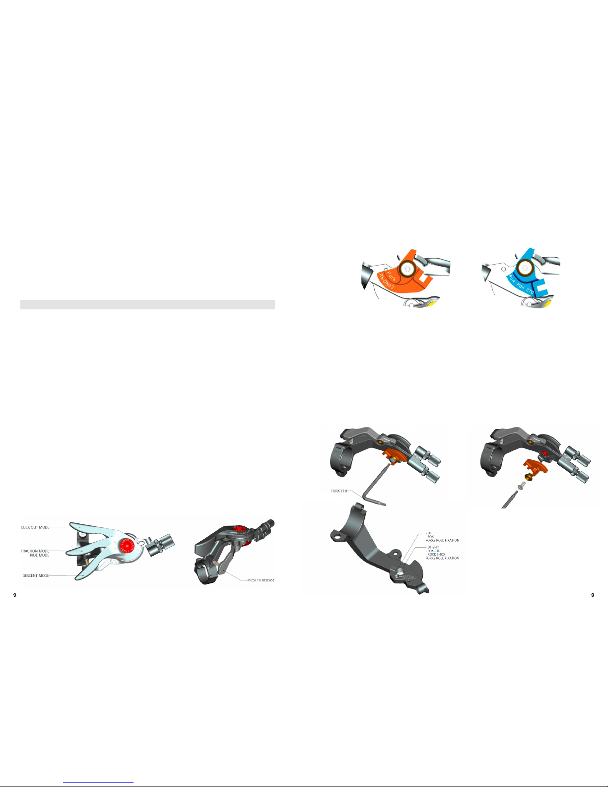
You will find the following positions on the remote lever:
For the assem bly of the remote control of the front fork lock-out 2 dif ferent cable rolls which
are changeable are existing.
The different roll for the pull of the fork remote ca ble can be changed within few minutes to
adapt the lever to your fork model/brand.
You will see on the downside of the roll the indication of the fork brand or the fo rk model.
SCOT T offe rs 2 different TWINLOC levers with following fork/rear shock co mbinations:
- FOX Nude with dif ferent rolls for FOX CTD fork and RockShox DNA 3 fork (SCOT T
Article number: 23 0097 )
- FOX CTD with different rolls for FOX CTD fork and Rock Shox DNA 3 fork (S COTT Article
number: 230098)
Please ki ndly note t hat the ca ble roll of a R ockShox DNA3 or FOX CTD fork‑lever is not
interch angeab le with th e regular rolls of 2 ste p forks. You need to use another lever!
For more details please contact your aut horized SCOTT deale r.
To change the rolls to match anoth er fork bran d pls follow the drawi ngs below :
ROLL FOR K MOUNTI NGROLL FOR K UNMOU NTING
09 |
2016 BIKE USE R MANUAL | GENIUSGENIUS | 2016 BIKE USER MANUAL
| 08
Page 6

L5
L1
L4
L2
L3
S6
S7
S4
S3S8
S9
S2 S1
S5S7S4
ENGLISHENGLISH
•
ASSEMBLY OF THE REMOTE CABLE
IMPORTANT!
Please make sure the lockout of SR AM/RockShox or FOX fork is ac tivated after tra nsport
correctly. Therefore please compress fork 5-10 times befo re following the ma nual on remote
cable installation and a djustment.
The lever should show on the downside of the cable roll the brand name of the fork you a re
going to use. Please do not try to use a RockShox roll with a FOX fork or vice versa.
1. To assemb le the cable please bring the
lever into the Desce nt Mode, push the
cable into the lever-eyelet as shown
on drawing below, push it through the
pre-cut c able housing and fix it at the
assembly unit on top of the right side of
the fork crown .
2. Fix the cable with the 2mm allen screw on the barrel adjuster
on the fork crown with a tightening torque of 0. 9Nm/8 lb/in,
cut the cable and secure it with a c able end-cap. Please refer
for this action also to the manua l of SRAM/ RockShox or FOX
attached to the bike.
TIP:
To check for accurate cable tension, p lease try to move the p lastic end cap of the cable
housing at the barrel adjuster on the remote lever. There should be “no -play” between cap
and barrel a djuster. In case of “play” please turn the barrel adjuster clock wise until “no -p lay ”.
•
FOX NUDE SHOCK AND TWINLOC REMOTE CONTROL LEVER
In the drawing of th e shock and remote lever, shown below, you will see the parts indicated
with numbers which will be use d in the manual for the adjustment and setup.
Parts List
S1 Front eyelet / Shock Bol t
S2 Re ar eyelet/ Sh ock Bolt
S3 Shock Housing
S4 Reboun d-Adjuster K nob
S5 Posi tive Chamber Valve
S6 Remote C ontrol Whe el
S7
Cable Fi xing Screw
(hidden behind remote wheel)
S8 Shock Piston
S9 SAG Indi cator (o-ring on piston)
L1 Remote Lever
L2 Rel ease button
L3 Remote Control Cables
L4 Ca ble Tension S crew Fork Remote
L5 Ca ble Tension S crew Shock Remote
11 |
2016 BIKE USE R MANUAL | GENIUSGENIUS | 2016 BIKE USER MANUAL
| 10
Page 7

ENGLISHENGLISH
•
BASIC SET-UP OF THE TWINLOC REMOTE CONTROL OF FOX
NUDE SHOCK
To ensure perfect f unction of th e FOX Nude shock it is very impor tant to follow the steps
shown be low exactly.
On Genius Carbon frames you will find an internal c able routing.
3. tighten the cabl e and fix the cablefixing
screw (S7) by turning it clockwise with a
2mm allen key and a max. tightening torque
of 1.6Nm.
Push the inner cable first through the remote lever in
the upper c able routing of th e lever and then through
the cable housing as shown below inside the to ptube .
On Genius alloy frames a re gular
outside cable routing, the outer
cable housing is fixed on c able
mount por ts with cable zippers.
1. loosen the cable fixing screw (S7) by
turning it cou nter clockwise with a 2mm
allen key.
2. insert a new cable via lever h ole and cab le
housing an d push it into the shock as shown
around the rem ote wheel (S6).
4. Check that the handlebar lever is in the
traction position. Refer to the following
diagrams.
5. cut the cable a pprox. 20mm away from
the remote whee l. Fix it by squeezing it
with pliers.
6. push a cable end -cap on th e cable until
it touches the e nd of the cable. Fix it by
squeezing it with pliers.
13 |
2016 BIKE USE R MANUAL | GENIUSGENIUS | 2016 BIKE USER MANUAL
| 12
Page 8

ENGLISHENGLISH
•
BASIC SET-UP OF THE TWINLOC REMOTE CONTROL OF FOX
CTD SHOCK
The assemb ly of the remote cab le and the setup of the FOX CTD rear shock is very similar to
the abovementioned asse mbly and setup of the FOX Nu de.
For more details on the FOX CTD please follow the details shown in the manuals of FOX
attached to this bike.
•
RECOMMENDED TOOLS FOR THE SHOCK SET-UP
For the set-up of the shock we recommend to use a shock p ump with a scale u p to 20
bars/30 0 psi with a special air valve conne ctor preventing from air getting away while
removing the pump from the shock valve, this will result in an exact air pressure.
Please note that air will flow into the hose and indicator when counterch ecking the air
pressure, so you have to set up again the recommende d pressure af ter this action.
Make sure to balan ce at least this air loss when you make a check of the air pressure of the
shock. Please also note that th e indicators of shock pumps have a tolerance of max . 10%.
•
SET-UP GENIUS WITH FOX NUDE OR FOX CTD SHOCK
The Set-Up of th e FOX Nude or FOX CTD Shock can be easy done within a few minutes.
IMPORTANT!
For all adjustments of the air spring the rem ote lever has to be in position “alltravel ”
To adjust the air pressu re of the air chamber of the FOX Nude o r FOX CTD Shock please
refer to the following instruction:
1. Remove the valve cap of the va lve (s5) located on the shock housin g (S3).
2. Mount the sh ock pump with its adaptor on the valve
3. Please take into acco unt that it takes so me air pressure from inside the shock to drive the
indicator on the pump. Make sure to balance at le ast this air loss when you make a che ck
of the air pressu re of the shock. Pls also note that the indicators of shock pumps have a
tolerance of max. 10%
4. Please use the FOX iRD App available at the iTunes Ap p store with following lin k:
https://itunes.apple.com/us/app/fox-intelligent-ride-dyna mics/id549 035102?mt=8&ignmpt=uo%3D4)
5. After downloading the app o n your mobile gear please follow the steps shown in th e app
and inflate the shock accordin g to the air pressure indicate d.
6. When you reached the needed pressure remove the p ump and put the valve cap on
the valve.
15 |
2016 BIKE USE R MANUAL | GENIUSGENIUS | 2016 BIKE USER MANUAL
| 14
Page 9

ENGLISHENGLISH
•
SAG
The SAG should be 14mm (700) respectively 12. 5mm (900 / 700 Plus) on the shock piston.
To check the adjustment, please fo llow as shown below:
1. sit on the bike, put your feet on the pedal
2. put your feet back on the groun d and stand over th e bike without bo uncing the bike
during this action
3. check if the o- ring (S9) on the shock piston (S8) has a distance of 14/12.5mm to the main
dust wiper/seal betwe en shock housing and pi ston.
- if the distance between the o-ring a nd the main dust wiper/seal is 14/12.5mm, the air
pressure is matching to your weight
- if the distance between the o-ring a nd the main dust wiper/seal is less than 14/12.5mm,
the air pressure of the air chamb er is too high and should be ca refully reduced by using
the bleed knob of the shock pump until the distance is 14/ 12.5mm.
- if the distance between the main dust wiper/seal is bigger than 14/12.5mm the air
pressure of the ai r chamber is too low and should b e increased by using the shock pump
until the distance is 14/12.5mm.
•
SET-UP OF REBOUND FOX NUDE OR FOX CTD SHOCK
“Rebou nd” describes the speed the shock comes back to its original length after absorbing
an obstacle.
By using the reb ound adjuster knob (S4) you ca n adjust the rebound step by s tep.
Please refer to the following instruction:
Ride your bike of f a pavement (remain in th e saddle) and check how many times it bounces.
- If it bounces 1-2 times, th e set up is good.
- If it bounces more than 3 times the rebound is too fast. Turn the knob 1-2 “clicks”
clockwise
- If it does not bounce the reb ound is too slow. Turn the knob 1 -2 “clicks” counter
clockwise.
IMPORTANT!
Note that you have to mount th e FOX Nude Shock always as shown be low.
Mounting the rear shock in a different position can cause severe damage to the frame, th e
linkage levers and the rear shock .
Same for the FOX CTD on some of the G enius models.
IMPORTANT!
After a disma ntlement of the rear shock, b oth fixing bolts should be tightened with a
tightening torque of 10Nm/8 8in-lbs.
If this is not don e correctly the re ar shock can be damaged.
17 |
2016 BIKE USE R MANUAL | GENIUSGENIUS | 2016 BIKE USER MANUAL
| 16
Page 10

ENGLISHENGLISH
•
SET-UP OF OTHER SHOCK MODELS
SCOTT str ongly reco mmends using only the FOX Nude (FOX CTD shock) with the
Genius bike, as we designed both p arts for a perfect matching combination with a linear
suspension rate.
Also on those sh ock models the SAG should be 14/12.5mm.
Other Shock Mode ls on Genius
If you want to use a different rear sho ck model tha n the one originally on the bike, please
make sure that the shock will not in any position hit the frame and cau se a damage to
the frame.
Please follow th e instruction below:
- Please make sure that the rear sh ock or its acce ssory parts do not touch the frame wh en
mounting or suspending.
- For doing so re lease the air/remove the coil, install the shock and compress the shock
completel y.
- If the shock touches the frame while doing so, do not use this shock in orde r to avoid
damage to frame, swingarm or shock.
•
HEADSET OPTIONS
Genius features a tapere d headset an d fork steerer
system to match with semi -integrated headsets
of the “50 -61 ”mm range with ID of Headtube of
44.0mm on top and 54 .9mm on th e lower end.
It is also possible to use forks with a standard 1 1/8 ” steerer tube when using a reducer
headset such as e.g.
Ritchey WCS C arbon Zero Tapered PF 50- 61mm 18mm U D for 1 1/18 " fork PRD 14860
•
BOTTOM BRACKET (BB) ON GENIUS
All frames of Genius (carbon and alloy) have a BB shell for BB92PF standard.
This matches to severa l bearing and crankset m odels of Shim ano, SRAM, FSA and others.
Please note that you do n ot need anym ore a space r on the right side of th e bearing cup
between frame housing and bearing cup.
Ritchey WCS C arbon Zero Tapered PF 50- 61mm 18mm UD PRD 13636
Ritchey PRO Taper ed PF 50- 61mm 12.9mm PRD 13 640
19 |
2016 BIKE USE R MANUAL | GENIUSGENIUS | 2016 BIKE USER MANUAL
| 18
Page 11

ENGLISHENGLISH
•
ADJUSTABLE BB HEIGHT
On Genius bikes equipp ed with the FOX Nude or the FOX CTD shock you can adjus t the BB
height above ground in 2 positions by flipping a ge ometry chip located on the linkage bar
shock mount.
•
FRONT DERAILLEUR (FD) MOUNTING DETAILS
On all Genius frames you will
find a Shimano E-type f ront
derailleur but fixed directly on
the swingarm without the plate
that is fixed normally between
the bottom bra cket bearing
cup and the bottom bracket
housing of the front triangle
or a SRAM D irect Mount
Typ e S3 FD.
Please note that you always
need to use the a dapter plate
attached to the bike or frame
set between chainstay and
front de railleur.
This adapter c an be ordered at the SCOT T distribution with parts number:
229728 FD M ount Geni us 2013 700-65 0B
229729 FD Mount Genius 2 013 900-29 - also to be u sed for the Genius 70 0 Plus
Please note that th e 2 sizes of the adapter s are not interchangeable!
1. low BB for lower center of gravity over ground
2. high BB for bigger clearance betwee n pedals/crankset and obsta cles on the ground
IMPORTANT!
It is not possible to use this geom etry chip with oth er shock models than the FOX Nude or
FOX CTD.
The shock might collide with pa rts of the frame or linka ge ba r.
21 |
2016 BIKE USE R MANUAL | GENIUSGENIUS | 2016 BIKE USER MANUAL
| 20
Page 12

ENGLISHENGLISH
•
CHAINGUIDE
The Carb on as well as the alloy frames of Genius can be fitted with ISCG c hainguide systems.
A set of all spare pa rts for this a ction can be ordered via the S COT T distribution with:
229730 ISCG adapto r Genius 2013
Details for the assembly on the carbon f rames of Genius:
The adaptor must be used in order to assemble the chainblocker on the ISCG05
chainguide system .
Please note that you need to assem ble the chain blocker exactly the way as shown below
and use all parts of the set.
Please also respect the dif ferent assembly positions for
SRAM an d Shimano front derailleurs
For 2x10 drivetrains you need to use 2 x2.5mm washers,
for 3x10 drive trains 1x 2.5m m washers bet ween adaptor/
frame and the chainblo cker as shown ab ove.
Details for the assembly on the alloy frames of Genius:
You can assemble th e chainblo cker directly on the integrated ISCG05 mount o n the BB shell.
Please respect the different assembly positions for SRAM and Shimano front derailleurs.
•
GENIUS CABLE ROUTING
The direct and straight ca ble system on all our full suspension mod els offers perfect shifting
perform ance combined with lightweight and high resistance against water and dir t.
CARBON FRONT FRAMES
The carbo n frames of G enius have an internal shiftin g
cable routin g with cable stops on the front end of the
downtube as shown in the diagram.
23 |
2016 BIKE USE R MANUAL | GENIUSGENIUS | 2016 BIKE USER MANUAL
| 22
Page 13

USE PLAS TIC GUIDE TO FI X THE BRAKE C ABLE
ENGLISHENGLISH
Please note that th e inner cables need to cros s each other
1 time on the inside of the downtube b efore you pull the m
out through the cable slot on the lower downside of the
downtube.
For the rear bra ke please asse mble the cable as shown
in the following drawings:
Please keep in mind to have a minimum distance of
40mm bet ween the brake hose and the BB housing as
abovementioned!
Push the cab les through th e cable guide as shown below
and fix the cable guide on the downtube with a 3mm allen
key and a tightening torque of max. 4Nm/35in/lbf.
Push the outer c able housings on the cab les into the cable
guide but ma ke sure to respect the n eeded le ngth as
shown in the next drawing!
Please make sure to respect the 40mm distan ce between th e cables an d the BB (bottom
bracket) housing to avoid “ghost-shiftin g” and/or damag es on the shif t cables and
brake hose.
Please fix the brake hose and the remote seatpos t
cable housing (if applicable) on the frame on the cable
mounts with the mount clips by following the routing
info as shown be low:
Please secure the clamps with a c able zipper as shown
in the following diagram:
The cable g uide can be o rdered via the S COTT distribution with parts number:
229723 BB Cable Gui de Genius (f. Carbo n Frame)
25 |
2016 BIKE USE R MANUAL | GENIUSGENIUS | 2016 BIKE USER MANUAL
| 24
Page 14

ENGLISHENGLISH
In addition to the derailleu r cables
and the brake h ose you also will see
a possibility for an integrated c able
routing of the seatpost remote on the
carbon version of Genius.
In order to seal th e housing po rts on
the frame you should use the p lugs
attached to the bike.
Please make sure to respect the 40mm distan ce between th e cables an d the BB (bottom
bracket) housing to avoid “ghost-shiftin g” and/or damag es on the shif t cables and
brake hose.
For the rear bra ke please asse mble the cable as shown in the following drawings:
•
ADJUSTMENT OF SEATPOST-HEIGHT
IMPORTANT!
The seatpost has to be inserted into the seattube at a minimum of 100mm.
Never use anoth er seatpost diameter than 3 1.6mm or try to use a shim/reducer between
seatpost and fra me.
ALLOY FRONT FRAMES
Please fix the derailleur cable housings, the
brake hose and the remote seatpost cable
housing (if applicable) on the frame on
the cable mounts with the mo unt clips by
following the routing info as shown:
229724 Cab le Clampi ng Set Geni us alloy 2013 one size
Please tighten the mount bolt with a
max. of 4Nm.
27 |
2016 BIKE USE R MANUAL | GENIUSGENIUS | 2016 BIKE USER MANUAL
| 26
Page 15

ENGLISHENGLISH
•
REPLACEABLE DROPOUT
On Genius bikes of model year 2013 you can replace the rear d erailleur hanger. Depending
on the diffe rent models you’ll find following options:
1. 142mm axle with RWS 142/12
This is available via the SCOTT distribution:
21 95 74 c omplete set of R WS 142/12
219577 r ight side rep laceable RD hang er
2. 135mm axle with RWS 135/5
This is available via the SCOTT distribution:
219572 co mplete set of RWS 135/5
219575 right side re placeable RD han ger
3. Regular 135mm rear axle with QR
This is available via the SCOTT distribution:
206 473 replaceable hanger
If you want to use anoth er RWS standard SCOT T also of fers after-market part s for specific
wheelset s for the following p arts via the SCOT T distribution:
21 95 74 R WS 135/12 p arts set
219576 right si de replace able RD ha nger
•
REAR DISC BRAKE MOUNT
Genius can be used with 2 dif ferent disc rotor sizes
on the rear brake.
The rear disc brake on Genius is Postmount (P M)
Standard on th e left seat stay and it is possible to use
disc rotors with 18 0 and 185 mm dia me te r.
Please note that fo r the assembly of 185mm rotor
you might need adapters/wash ers betwee n the PM
port on the frame and th e brake calliper.
For 185m m rotor diameter you will need 2 red anodized spacers that can be ordered via the
SCOT T distribution with:
219568 Brake Mount Adapt.Spacers 4mm f/185mm
•
FRONT FORK SET-UP/CHANGE OF FRONT FORK
For the set up of the front fork plea se use the fork sp ecific manual attached to the bike.
We recommend using front forks with a travel of 150mm (700), 130mm (900) and
140mm(700 Plus), as this will not influence the ge ometry an d alter handling of the bike.
For details on the technical length of the reco mmende d forks please refer to the Tech Info
Chart before mentioned.
•
PIVOT MAINTENANCE
The pivot and be arings on S COTT Genius are extremely easy to maintain.
An external treatment with a grease spray after ever y bike wash is all you have to do. We
do not recommend heavy grease sprays since th ese will leave a film o n the part s which is
difficult to remove. We recommen d the same for th e chain also.
If you have to change the bearings you c an order the m included in a service kit at your local
SCOT T dealer or buy them with international parts number as shown above in the specs list
in a hardware sto re.
In case of a change of the bearings or of the rear swingarm you sh ould contac t your local
SCOT T dealer as you need special tools for disassembly and ass emb ly.
29 |
2016 BIKE USE R MANUAL | GENIUSGENIUS | 2016 BIKE USER MANUAL
| 28
Page 16

ENGLISHENGLISH
•
WARRANTY
SCOT T bikes are made using the most innovative production and quality methods. They are
equippe d with best comp onents of well known part s suppliers.
Doing so SCOTT warrants its frames and swingarms for five years (subject to com pliance
with maintenan ce ranges, see below) and SC OTT fo rks (provided it is a fork of SCOT T) for
two years for defects in material and/or workman ship in case of purchase of completely
assembled bikes.
This warrant y of 5 years for the f rames shall only be granted in case once a yea r a
maintenance service has been effected accordin g to maintenance re quirement s as set forth
in this manual by an authorise d SCOT T dea le r.
The authorised SCOT T dealer shall confirm the effected annu al maintenan ce service by
stamp and signature.
In case such a n annual maintenance ser vice has not been effected the warranty of 5years
for the frame shall be reduced to 3 years.
Costs for maintenance and service have to be born by the owner of the SCOTT bike.
On Gambler, Voltage Fr and Volt-X the warranty period is limited to 2 years.
The warrant y period starts at the day of purchase. This warranty is limited to the first buyer,
what means th e first person who uses the bike and only with th e use it was made for.
Furtherm ore, this warra nty is limited to purchases via authorized SCOT T-dealers
The warrant y is solely gra nted in case of purchase of a completely assembled bike to the
explicit exclusion of p urchases of not co mpletely assembled bikes.
In case of a warranty claim the decision to repair or to replace the d efective par t is up to
SCOT T. Non defective parts will only be replace d at the guarantee’s own expense.
Fair wear and tear is not covered by the warranty.
A complete list of all parts of wear and tear can be found in the n ext chapter of this manual.
In addition , you will find at th e end of this manual a protocol for the handing over of the
bike which will remain in copy at the SCOTT dealer af ter acceptance and signature of the
cons um e r.
It is obligator y to show this protocol of ha nding over together with the defec tive part in ca se
of a warranty cl aim given that it provid es evidence of purchase. Oth erwise no warranty is
grante d.
In principl e, this warranty is granted worldwide. Clai ms must be made through an authorized
dealer, for information regarding the nearest dealer, write or call th is company or the national
SCOT T distributor.
Normal wea r, accident, neglect, abuse , improper a ssembly, improp er maintenance by other
than an autho rized dealer o r use of part s or devices not consistent with the use originally
intended for the bicycle as sold are not covered by this warranty.
Hereby SCOTT grants a voluntarily manufacturer’s warranty. Additional entitlements
according to natio nal warrant of m erchantability are reserved.
For warranty info on the Fox Nude shock please refer to the attach ed manual of Fox Nude .
•
WARRANTY
Model ...................................................................................
Yea r .....................................................................................
Size ......................................................................................
Frame Nr. ................................................................................
Shock Nr. ................................................................................
Date of purchase .........................................................................
31 |
2016 BIKE USE R MANUAL | GENIUSGENIUS | 2016 BIKE USER MANUAL
| 30
 Loading...