

www.scot t-sport s.com
BIKE OWNER’S MANUAL 2015
All right s reserved © 2014 SC OTT Sports SA
SCOTT Spo rts SA | 17 Route du Cro chet | 1762 Givisiez | Sw itzerland
Distrib ution: SSG (Europ e) Distrib ution Center SA
P.E.D Zon e C1, Rue Du Kiel l 60 | 6790 Aubang e | Belgium
V4.3/19012015
SCOTT
GENIUS

02
GENIUS | BIKE OWN ER’S M ANUAL 20 15 BIKE OWN ER’S M ANUAL 20 15 | GENIUS
03
www.scot t-sport s.com
ENGLISH
ENGLISH
The Geniu s should be a djusted exac tly to the current rider for
reaching maximum safet y and fun wh ile riding.
All adjustm ents should be done at your local S COTT dealer or
following this manual’s instructions.
In order to avoid technical prob lems or any ha rm please contact in
case of doubts your authorized SCOT T dealer.
CONTENT
Genius Concept. . . . . . . . . . . . . . . . . . . . . . . . . . . . . . . . . . . . . . . . . . . . 04
Geom et ry/ Technical Data Genius 650B/27.5”. . . . . . . . . . . . . . . . . . . . . . . . . 05
Geom et ry/ Technical Data Genius 29”. . . . . . . . . . . . . . . . . . . . . . . . . . . . . . 06
TC Shock Technology/Twinloc Levers. . . . . . . . . . . . . . . . . . . . . . . . . . . . . . 07
Assembly of the Rem ote Cable . . . . . . . . . . . . . . . . . . . . . . . . . . . . . . . . . . .10
FOX Nude Shock and Twinloc Remote Control Lever . . . . . . . . . . . . . . . . . . . . . 11
Basic Set-Up of the Twinloc Remote Control of FOX Nude Shock . . . . . . . . . . . . .12
Basic Set-Up of the Twinloc Remote Control of Fox CTD Shock . . . . . . . . . . . . . . 14
Recommended Tools for the Shock Set-Up . . . . . . . . . . . . . . . . . . . . . . . . . . .14
Set-Up Genius with FOX Nude or FOX CTD Shock. . . . . . . . . . . . . . . . . . . . . . .15
SAG . . . . . . . . . . . . . . . . . . . . . . . . . . . . . . . . . . . . . . . . . . . . . . . . . . . .16
Set-Up of Rebound FOX Nude or FOX CTD Shock. . . . . . . . . . . . . . . . . . . . . . .16
Set-Up of Other Shock Models . . . . . . . . . . . . . . . . . . . . . . . . . . . . . . . . . . .18
Headset Options . . . . . . . . . . . . . . . . . . . . . . . . . . . . . . . . . . . . . . . . . . . . 18
Bottom Bracket (BB) on Genius . . . . . . . . . . . . . . . . . . . . . . . . . . . . . . . . . . 19
Adjustable BB Height . . . . . . . . . . . . . . . . . . . . . . . . . . . . . . . . . . . . . . . . 20
Front Derailleur (FD) Mounting Details . . . . . . . . . . . . . . . . . . . . . . . . . . . . . .21
Chainguide . . . . . . . . . . . . . . . . . . . . . . . . . . . . . . . . . . . . . . . . . . . . . . 22
Genius Cable Routing . . . . . . . . . . . . . . . . . . . . . . . . . . . . . . . . . . . . . . . . 23
Adjustment of Seatpost-Height. . . . . . . . . . . . . . . . . . . . . . . . . . . . . . . . . . 27
Replaceable Dropout . . . . . . . . . . . . . . . . . . . . . . . . . . . . . . . . . . . . . . . . 28
Rear Disc Brake Mount . . . . . . . . . . . . . . . . . . . . . . . . . . . . . . . . . . . . . . . 28
Front Fork Se t- Up/Change of Front Fork. . . . . . . . . . . . . . . . . . . . . . . . . . . . 29
Pivot Maintenance . . . . . . . . . . . . . . . . . . . . . . . . . . . . . . . . . . . . . . . . . . 29
Warranty. . . . . . . . . . . . . . . . . . . . . . . . . . . . . . . . . . . . . . . . . . . . . . . . 30
04
GENIUS | BIKE OWN ER’S M ANUAL 20 15 BIKE OWN ER’S M ANUAL 20 15 | GENIUS
05
ENGLISH
ENGLISH
GENIUS CONCEPT
The new Genius is the result of 2 years of research and development for on e of the
lightest trail/marathon bike frame set available on the market, hitting th e scale at
below 2300g (5lbs) includi ng the frame, FOX Nude /CTD shock and the u nique
TWINLOC remote control.
SCOTT’s focus was not only on light weight but al so on a durable and stiff frame with
an innovative suspension technology in combination with an optimized ki nematics of
the rear swingarm.
The combination of an optimized kinematics with an extraordinary suspension
technolog y closes the ga p between superlight d ual suspe nsion race bikes (e.g.
SCOTT Spark) and the new gene ration of all- mountain bikes (e.g. SCOT T Geniu s LT) .
Genius was designed for riders lo oking for a du al suspen ded trail an d marathon bike
offering a maximum rea r wheel travel of 150mm (27.5”)/130mm (29 ”).
SCOTT does not see frame and rear shock as single com ponents which are
assembled together on a bike, but as a con cept with all the se components working
together and offering an outrageous func tion by matching perf ectly.
The Geniu s Concept is based on a multi-pivot techn ology.
The damping performance was improved in comparison to the already famous
“old” Genius, and with reworking also the kinematics we were able to reach a better
progressio n in the end of the stroke/travel of the swingarm.
The SCOT T system, u sing the Nude shock, named TC (Traction C ontrol) will all ow
you to reduce by remote co ntrol the rear wh eel travel from 1 50mm (27.5”)/ 130mm
(29”) to 10 0mm (27.5”)/90 mm (29”) including a more progres sive spring rate but
still offering a supple b reak away. In addition the SAG is reduced and the geometry
gets steeper.
Some models of Geniu s use also the FOX C TD shock which offers i nstead of the
Traction Mode a Platform (Ride Mode) in between Lock-out Mod e and Descent Mode
No power will be lost and an optimum power transfer is guaranteed as the swingarm ,
in contrary to locked or autom atic-lockin g systems, c an follow the tra il surface and
will offer perfect traction an d higher speed while standing on the pedals.
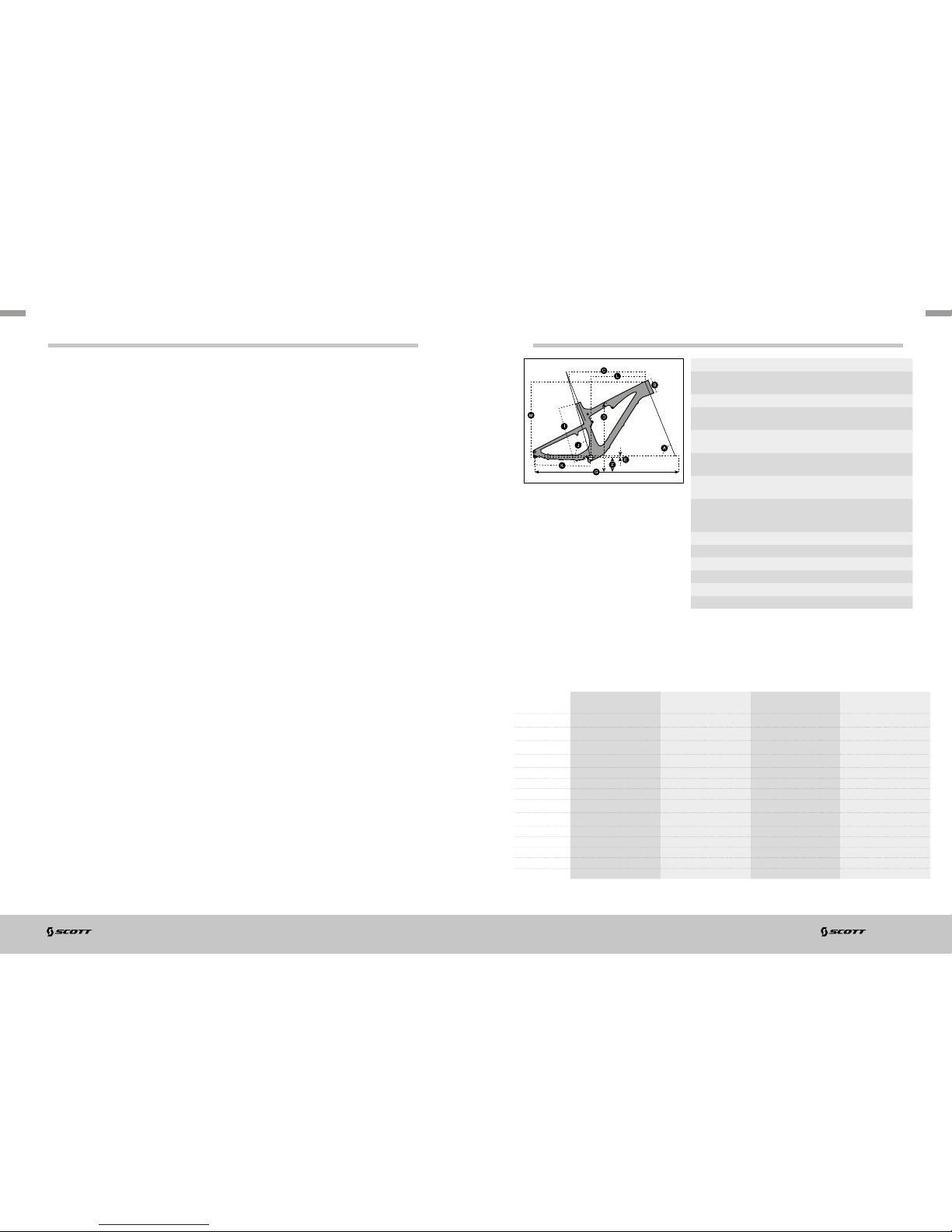
GEOMETRY/TECHNICAL DATA GENIUS 650B/27.5”
Trav el 150/ 100/0 mm
Suspension
Ratio
2.72
Piston stroke 55mm
Shock length
(Eye to Eye)
200mm
Hardware
Mainframe
22. 2mm x 6mm
Hardware
Swingarm
22. 2mm x 6mm
Seatpost
diameter
31.6mm
Headset semi integ r. for tapered 1 1 /8-1.5
(44/54.9mm Inner diamete r of frame) or
with 1 1/8 strai ght (44.0m m)
Fork travel 150mm
Fork length 544mm
BB housing BB PF 92
Front derailleur Shiman o E-Type/SRAM S3 dire ct mount
Bearings 2 x IGUS / 6 x 68 02 (24 x 15 x 5)
Max Tire Wid th 57mm/2 .25”
S S M M L L XL XL
LOW BB SETTI NG HIGH BB SE TTING LOW BB SE TTING HIG H BB SETTING L OW BB SETTING H IGH BB SET TING LOW BB SET TING HIGH BB S ETTING
A
HEAD TUBE
ANGLE
67.9 ° 68.4 ° 67.9 ° 68.4 ° 67.9 ° 68.4 ° 67.9 ° 68.4 °
B
HEAD TUBE
LENGTH
100.0 mm 3.9 in 100.0 mm 3. 9 in 110.0 mm 4 .3 in 110.0 mm 4 .3 in 120.0 mm 4.7 in 120.0 mm 4.7 in 135. 0 mm 5. 3 in 135 .0 mm 5 .3 in
C
TOP TUB E
HORIZONTAL
569.9 mm 2 2.4 in 568 .6 mm 22.4 in 5 99.9 mm 23. 6 in 598.6 m m 23.6 in 624 .9 mm 24.6 in 623.6 mm 24. 6 in 649.9 mm 25 .6 in 648.6 m m 25.5 in
D
STANDOVER
HEIGHT
773.1 mm 30.4 in 77 5.9 mm 30. 5 in 774. 6 mm 30.5 in 777.6 mm 30.6 in 80 7.0 mm 31. 8 in 810.4 mm 31 .9 in 809. 0 mm 31.9 in 8 12.4 mm 32.0 in
E
BB OFFSET -11.6 m m -0. 5 in -6 .1 mm -0 .2 in - 11.6 mm -0.5 i n -6.1 m m -0. 2 in -11 .6 mm - 0.5 in - 6.1 mm - 0.2 in -11.6 m m -0 .5 in -6 .1 mm -0 .2 in
F
BB HEIGHT 344.9 m m 13.6 in 350.4 mm 13. 8 in 344 .9 mm 13 .6 in 350.4 mm 13.8 in 3 44.9 mm 13.6 in 350.4 mm 13.8 in 3 44.9 mm 13.6 in 3 50.4 mm 13.8 in
G
WHEEL BASE 1,122.7 m m 44.2 in 1,121 .8 mm 44.2 i n 1,153.8 mm 45.4 in 1,152.9 mm 45.4 in 1,179 .9 mm 46.5 in 1,179.0 mm 46.4 in 1 ,206.6 m m 4 7.5 in 1,20 5.7 mm 47.5 in
H
BB CENTER TO
TOPTUBE CENTER
I
BB CENTER TO TOP
OF SEATTUBE
415.0 mm 16. 3 in 415.0 mm 16.3 in 440.0 mm 17.3 in 440.0 mm 17.3 in 475.0 mm 18.7 in 475.0 m m 18 .7 in 510.0 mm 20 .1 in 510.0 mm 20.1 i n
J
SEAT ANG LE 74. 0 ° 74 .5 ° 74.0 ° 74. 5 ° 74 .0 ° 74 .5 ° 74.0 ° 74. 5 °
K
CHA INS TAY 439.0 mm 17.3 in 439.0 mm 17.3 in 439.0 mm 17.3 in 439.0 mm 17.3 in 439.0 mm 17.3 in 439.0 mm 17.3 in 439.0 mm 17.3 in 439.0 mm 17.3 in
L
REACH 401 .4 mm 15.8 in 406.1 mm 16.0 in 428.7 mm 16.9 in 433.4 mm 1 7.1 in 451.1 mm 1 7.8 in 4 55.7 mm 17.9 in 472.1 mm 18.6 in 476.7 mm 18. 8 in
M
STAC K 58 8.8 mm 23. 2 in 585 .5 mm 23.1 in 598.1 m m 23 .5 in 594 .7 mm 23.4 in 607.3 mm 23 .9 in 603.9 m m 23.8 in 621.2 mm 24.5 in 6 17.7 m m 24.3 in
N
STEM LENGTH 60.0 mm 2.4 in 60.0 mm 2. 4 in 70.0 mm 2.8 in 70.0 mm 2.8 in 80.0 mm 3 .1 in 8 0.0 mm 3.1 in 90.0 mm 3. 5 in 90.0 mm 3.5 in
06
GENIUS | BIKE OWN ER’S M ANUAL 20 15 BIKE OWN ER’S M ANUAL 20 15 | GENIUS
07
ENGLISH
ENGLISH
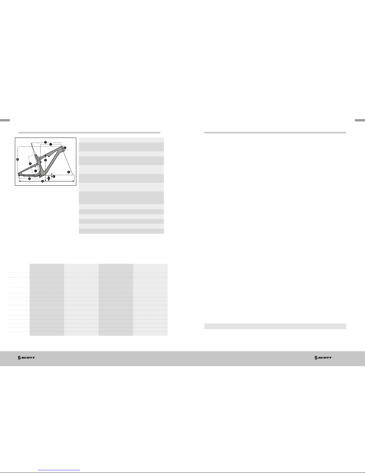
GEOMETRY/TECHNICAL DATA GENIUS 29”
Trav el 130/9 0/0mm
Suspension
Ratio
2.60
Piston stroke 50mm
Shock length
(Eye to Eye)
190mm
Hardware
Mainframe
22. 2mm x 6mm
Hardware
Swingarm
22. 2mm x 6mm
Seatpost
diameter
31.6mm
Headset semi integ r. for tapered 1 1 /8-1.5
(44/54.9mm Inner diamete r of frame) or
with 1 1/8 strai ght (44.0m m)
Fork travel 130mm
Fork length 540mm
BB housing BB PF 92
Front derailleur Shiman o E-Type/SRAM S3 dire ct mount
Bearings 2 x IGUS / 6 x 68 02 (24 x 15 x 5)
Max Tire Wid th 57mm/2 .25”
S S M M L L XL XL
LOW BB SETTI NG HIGH BB SE TTING LOW BB SE TTING HIG H BB SETTING L OW BB SETTING H IGH BB SET TING LOW BB SET TING HIGH BB S ETTING
A
HEAD TUBE
ANGLE
68.9 ° 69.4 ° 68.9 ° 69.4 ° 69.0 ° 69.4 ° 69.0 ° 69.4 °
B
HEAD TUBE
LENGTH
100.0 mm 3.9 in 100.0 mm 3. 9 in 100.0 mm 3.9 in 100.0 mm 3 .9 in 110.0 mm 4 .3 in 110.0 mm 4.3 in 12 0.0 mm 4.7 in 120.0 mm 4.7 in
C
TOP TUB E
HORIZONTAL
570.3 mm 22.5 in 5 69.0 mm 22.4 i n 600.3 mm 23.6 in 598.9 mm 2 3.6 in 625 .2 mm 24.6 in 623.8 mm 24.6 in 650.2 mm 25.6 in 64 8.8 mm 25. 5 in
D
STANDOVER
HEIGHT
770.4 mm 30.3 in 772 .8 mm 30.4 in 7 72.8 mm 30. 4 in 775.5 m m 30.5 in 803.0 m m 31.6 in 80 6.1 mm 31.7 in 800.6 mm 31.5 in 803.8 mm 31.6 in
E
BB OFFSET -34.5 mm -1.4 in -2 9.1 mm -1.1 in -3 4.5 mm -1 .4 in -29.0 m m -1 .1 in -34.0 mm -1 .3 in -28.5 mm - 1.1 in -34.0 mm - 1.3 in -28 .4 mm -1.1 i n
F
BB HEIGHT 335. 5 mm 13.2 in 340. 9 mm 13.4 in 335.5 mm 13.2 i n 341.0 mm 13.4 in 336.0 mm 13.2 in 341 .5 mm 13.4 in 336.0 mm 13.2 in 341. 6 mm 13.4 in
G
WHEEL BASE 1,1 12.2 mm 43 .8 in 1,111.8 mm 43.8 in 1,142.2 m m 45.0 in 1,141.8 mm 45. 0 in 1,168 .0 mm 46.0 in 1,1 67.6 mm 46.0 in 1 ,193.9 mm 47.0 in 1,193. 5 mm 4 7.0 in
H
BB CENTER TO
TOPTUBE CENTER
I
BB CENTER TO TOP
OF SEATTUBE
415.0 mm 16. 3 in 415.0 mm 16.3 in 440.0 mm 17.3 in 440.0 mm 17.3 in 475.0 mm 18.7 in 475.0 m m 18 .7 in 510.0 mm 20 .1 in 510.0 mm 20.1 i n
J
SEAT ANG LE 73. 9 ° 74.4 ° 73.9 ° 74.4 ° 74. 0 ° 74. 4 ° 74 .0 ° 74 .4 °
K
CHA INS TAY 450.0 mm 17. 7 in 449.0 mm 17. 7 in 450.0 mm 1 7.7 in 449. 0 mm 1 7.7 in 44 9.9 mm 17.7 i n 4 48.9 mm 17.7 in 449.9 mm 17. 7 in 448. 9 mm 1 7.7 in
L
REACH 394.2 m m 15. 5 in 3 99.2 mm 15.7 in 424.2 mm 16.7 in 429.1 mm 16. 9 in 447. 1 mm 17. 6 in 4 51.8 mm 1 7.8 i n 4 69.4 mm 18.5 in 474. 1 mm 18.7 in
M
STAC K 770.4 mm 30.3 i n 772.8 mm 3 0.4 in 772. 8 mm 30.4 in 77 5.5 mm 30. 5 in 8 03.0 mm 31 .6 in 806.1 mm 31 .7 in 800.6 mm 31 .5 in 8 03.8 mm 3 1.6 in
N
STEM LENGTH 60.0 mm 2.4 in 60.0 mm 2. 4 in 70.0 mm 2.8 in 70.0 mm 2.8 in 80.0 mm 3 .1 in 8 0.0 mm 3.1 in 90.0 mm 3. 5 in 90.0 mm 3.5 in
TC SHOCK TECHNOLOGY/TWINLOC LEVERS
The hear t of the TC-System is the FOX Nude Shock mad e by FOX, offering three
functions which make this system possible.
The TWIN LOC XL remote control lever is the evolution of the already outstanding
TRACLOC system of SCOTT.
While TRACLOC allowed only th e change on the SCOT T TC rear shocks between
the SCOTT patented Lock-out, traction and full -mode on th e fly from the handleba r,
the TWIN LOC allows also the remote control of th e front fork to shift between
lock-out and o pen mode at the same time when you change the modes on the
SCOTT rear shox.
In combination with FOX 34 CTD o r FOX 32 CTD forks it is also possible to have a
platform mode on the fork.
The 3 modes of C TCD in combin ation with FOX Nude are:
- Climb Mode : lock-out rear, lock-out f ront
- Traction Mode: traction mode rear (incl. Ge ometry ch ange and re duced travel),
platform mode front
- Descent Mode: f ull travel rear (D escent), full travel f ront
The 3 modes of C TD in combi nation with the FOX C TD shock are:
- Climb Mode : lock-out rear, lock-out f ront
- Ride Mode: plat form (Ride) mode rear, platform mo de front
- Descent Mode: f ull travel rear (D escent), full travel f ront
Therefore SCOT T offers 2 diffe rent TWI NLOC levers with following fork /rear shock
combinations:
- FOX Nude with different rolls for FOX CT D fork and Roc kShox DNA 3 fo rk
(SCOTTA rticle number: 23 0097 )
- FOX CTD with different rolls for FOX CTD fork and Rock Shox DNA 3 for k
(SCOTTA rticle number: 23 0098)
Please note that the FOX CTD rear shock does n ot offer a traction mode, but a
platform mode. In contrary to FOX Nude th e air-chamber volume of the p ositive
chamber remains the same throughout the different modes
IMPORTANT!
You can only assem ble the TWINLOC remote lever in “left side upward positi on” on
the handlebar.
08
GENIUS | BIKE OWN ER’S M ANUAL 20 15 BIKE OWN ER’S M ANUAL 20 15 | GENIUS
09
ENGLISH
ENGLISH
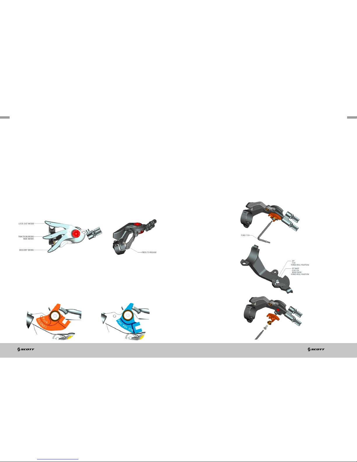
You have 3 positions of the TWINLOC remote le ver.
1. LOCK OUT MODE:
the shock is locked; climbing on asphalt roads is now possible without any power
loss. Simultaneous a blow-off-system prevents the shock being damage d in case the
rider did not open the syste m while crossing obstacles.
2. TRACTION/RIDE MODE:
For Traction: by reducing the internal chambe r volume inside the shock the travel of
the shock will be reduced to around 80% (approx . 120/104mm) the charac teristic of
the air spring gets harder, the SAG is shorter and the geom etry steep er. This results
in climbing without “bobbing” an d offers still optimum tra ction of the rear wheel.
For Ride: by adding a platfor m on the compre ssion damping system the shock will
not bounce while standing on the pedals
3. DESCENT MODE:
full travel of 150/130mm (27. 5 ”/2 9”)
You will find the following positions o n the remote lever:
For the assem bly of the remote control of the front fork lock-out 2 different cable
rolls which are changeable are existing .
The diffe rent roll for the p ull of the fork re mote cable c an be changed within few
minutes to adapt the lever to your fork m odel/brand.
You will see on the downside of the roll the indication of th e fork brand or the
fork model.
SCOTT offers 2 different TWINLOC levers with following fork/rear shock
combinations:
- FOX Nude with different rolls for FOX CT D fork and Roc kShox DNA 3 fo rk (SCOT T
Article number: 230097)
- FOX CTD with different rolls for FOX CTD fork and Rock Shox DNA 3 for k (SCOT T
Article number: 230098)
Please ki ndly note t hat the c able roll of a RockS hox DNA3 or FOX C TD fork-lever
is not inte rchang eable with the reg ular rolls of 2 step forks. You nee d to use
another lever!
For more details please contact your au thorized SCOTT d eal er.
To change the rolls to match another fork b rand pls follow the drawings below:
ROLL FORK MOUNTING
ROLL FORK UNMOUNTING

10
GENIUS | BIKE OWN ER’S M ANUAL 20 15 BIKE OWN ER’S M ANUAL 20 15 | GENIUS
11
L5
L1
L4
L2
L3
S6
S7
S4
S3S8
S9
S2 S1
S5S7S4
ENGLISH
ENGLISH
ASSEMBLY OF THE REMOTE CABLE
IMPORTANT!
Please make sure the lockout of SRAM/ RockShox or FOX fork is activated after
transpor t correctly. Therefore please compress fork 5-10 times before following the
manual on re mote cable installatio n and adjustment.
The lever should show on the down side of the ca ble roll the brand name of th e fork
you are going to use. Please do n ot try to use a RockShox roll with a FOX fork or
vice versa .
1. To assemble the cable please bring
the lever into the Descent Mode,
push the cable into the levereyelet as shown on drawing below,
push it throug h the pre-cut cable
housing an d fix it at the assembly
unit on top of the rig ht side of the
fork crown.
2. Fix the cable with th e 2mm allen screw on the barrel
adjuster on the fork crown with a tightening torque of
0.9Nm /8 lb/in, cut the cable and secure it with a ca ble
end-cap. Please refer for this ac tion also to the manual
of SRAM/ RockShox or FOX attached to the bike.
TIP:
To check for accurate ca ble tension , please tr y to move the plastic end cap of the
cable hou sing at the barrel adjuster on the remote lever. There should be “no-play”
between cap and barre l adjuster. In case of “play” please turn the b arrel adju ster
clockwise until “no -pl ay”.
FOX NUDE SHOCK AND TWINLOC REMOTE CONTROL
LEVER
In the drawing of th e shock and remote lever, shown below, you will see the par ts
indicated with numbers which will be used in the manual for the adjustment and setup.
Parts List
S1 Front eyelet / Shock Bo lt
S2 Rear eyelet / Shock Bolt
S3 Shock Hou sing
S4 Rebou nd-Adjuster Knob
S5 P ositive Cha mber Valve
S6 Rem ote Control Wheel
S7 Cable F ixing Screw
(hidden behind remote wheel)
S8 Shock Piston
S9 SAG In dicator (o-ring on pisto n)
L1 Remote Lever
L2 R elease b utton
L3 Remote Control Cables
L4 C able Tension Screw Fork Re mote
L5 C able Tension Screw Shoc k Remote

12
GENIUS | BIKE OWN ER’S M ANUAL 20 15 BIKE OWN ER’S M ANUAL 20 15 | GENIUS
13
ENGLISH
ENGLISH
BASIC SET-UP OF THE TWINLOC REMOTE CONTROL OF
FOX NUDE SHOCK
To ensure perfec t functio n of the FOX Nude sh ock it is very importa nt to follow the
steps shown below exactl y.
On Genius Carbon f rames you will f ind an internal cable ro uting.
1. loosen the cable fixing screw (S7) by
turning it cou nter clockwise with a 2mm
allen key.
Push the inn er cable f irst through the remote
lever in the upper cable routing of the lever an d
then through the cable housing as sh own below
inside the toptube.
On Genius alloy frames a regular
outside cable routing , the outer
cable hou sing is fixed on cable
mount por ts with cable zippers.
2. insert a new cable via lever ho le and
cable hou sing and pu sh it into the
shock as shown around the re mote
wheel (S6).
3. tighten the cable and fix the ca blefixing
screw (S7) by turning it clockwise with
a 2mm allen key and a max. tighten ing
torque of 1.6Nm.
4. Check that the
handlebar lever
is in the traction
position. Refer to the
diagram be low.
5. cut the cable ap prox. 20mm away from
the remote wheel. Fix it by sque ezing it
with pliers.
6. push a cable end-cap on the cable until
it touches the e nd of the cable. Fix it by
squeezing it with pliers.

14
GENIUS | BIKE OWN ER’S M ANUAL 20 15 BIKE OWN ER’S M ANUAL 20 15 | GENIUS
15
ENGLISH
ENGLISH
BASIC SET-UP OF THE TWINLOC REMOTE CONTROL OF
FOX CTD SHOCK
The assembly of the remote cable and the setup of the FOX CTD re ar shock is very
similar to the abovementioned assemb ly and setup of th e FOX Nude.
For more details on the FOX CTD please follow th e details shown in the manuals of
FOX attached to th is bike
RECOMMENDED TOOLS FOR THE SHOCK SET-UP
For the set-up of the shock we recommend to use a shock pump with a scale up
to 20 bars/30 0 psi with a special air valve con nector preventing from air getting
away while removing the pump from the shock valve , this will result in an exact air
pressure.
SET-UP GENIUS WITH FOX NUDE OR FOX CTD SHOCK
The Set-Up of the FOX Nude or FOX CTD Shock can be e asy done within a few
minutes .
IMPORTANT!
For all adjus tments of the air spring the remote lever has to be in position “alltravel”
To adjust the air pressure of the air chamber of the FOX Nude or FOX CTD Shock
please refer to the following instruction:
1. Remove the valve cap of the valve (s5) located on the shock housin g (S3).
2. Mount the sho ck pump with its adaptor on the valve
3. Please take into acco unt that it takes some air pres sure from inside the shock to
drive the indic ator on the pum p. Make sure to balance at least this air loss when
you make a check of the air pressure of the shock . Pls also note that the indic ators
of shock pum ps have a tolerance of max. 10%
4. Please use the FOX iRD App available at the iTunes App store with following link:
https://itunes.apple.com/us/app/fox-intelligent-ride-dynamics/
id549035102?mt=8 &ign-mpt=uo%3D4)
5. After downloading the app o n your mobile g ear please follow the steps shown in
the app and inflate the shock according to the air pressure indicated .When you
reached the needed pressure remove the pump and put the valve cap on the valve
Please note that air will flow into the hose and indicator when counterchecking the
air pressure , so you have to set up again the recommended pressure after this action .
Make sure to bala nce at least th is air loss when you make a check of the air pressure
of the shock . Please also note that the indicators of shock pumps have a tolerance of
max. 10% .

16
GENIUS | BIKE OWN ER’S M ANUAL 20 15 BIKE OWN ER’S M ANUAL 20 15 | GENIUS
17
ENGLISH
ENGLISH
SAG
The SAG should b e 14mm (27.5”/650B) respectively 12.5 mm (29”) on the shock
piston .
To check the adjustm ent, please follow as shown below:
1. sit on the bike, put your feet on the pedal
2. put your feet bac k on the ground and stand over the bike without b ouncing th e
bike during this action
3. check if the o-ring (S9) on the sho ck piston (S8) ha s a distance of 14/12. 5mm to
the main dus t wiper/seal between shock housing and pis ton.
- if the distance between the o-ring and th e main dust wi per/seal is 14/12.5mm, the
air pressure is matching to your we ight
- if the distance between the o-ring and th e main dust wi per/seal is less than
14/12. 5mm, the air pressu re of the air chamber is too hig h and should be carefu lly
reduced by using the bleed knob of the sho ck pump until the distance is
14/12.5mm.
- if the distance between the main dust wipe r/seal is bigger than 14/ 12. 5mm the air
pressure of the air chamber is too low and should be increased by using the shock
pump until the distance is 1 4/12.5mm.
SET-UP OF REBOUND FOX NUDE OR FOX CTD SHOCK
“Rebou nd” desc ribes the speed the sho ck comes back to its original length af ter
absorbing an obstacle.
By using the rebound adjuster knob (S 4) you can adjust the rebound step by ste p.
Please refer to the following instruction:
Ride your bike of f a pavement (remain in the saddle) and check how many times it
bounces.
- If it bounces 1-2 time s, the set up is good.
- If it bounces more than 3 times the rebound is too fast. Turn the knob 1-2 “clicks”
clockwise
- If it does not boun ce the rebound is too slow. Turn the knob 1-2 “clicks” counter
clockwise.
IMPORTANT!
Note that you have to mount the FOX Nude Shock always as shown b elow.
Mounting th e rear shock i n a different position ca n cause severe d amage to the
frame, the linkage levers and the rear shock.
Same for the FOX CTD on some of th e Genius models.
IMPORTANT!
After a dismantlement of the rear shock, both fixing bolts should be tightened with a
tightening torq ue of 10Nm/88in-lbs.
If this is not done correctly the rear shock can be damaged.

18
GENIUS | BIKE OWN ER’S M ANUAL 20 15 BIKE OWN ER’S M ANUAL 20 15 | GENIUS
19
ENGLISH
ENGLISH
SET-UP OF OTHER SHOCK MODELS
SCOTT str ongly recommend s using o nly the FOX Nu de (FOX CTD shock) with t he
Genius bike, as we designed both parts for a perfec t matching com bination with a
linear suspension rate.
Also on those shock mode ls the SAG should be 14/12.5mm.
Other Shock Models on Genius
If you want to use a dif ferent rear shock mod el than the on e originally on the bike,
please make sure that the sho ck will not in any position hit the frame and cause a
damage to the frame.
Please follow the instruc tion below:
- Please make sure that the rear shock or its accessory par ts do not touch the frame
when mounting or suspending.
- For doing so release the air/remove the coil, install the shock and comp ress the
shock completely.
- If the shock touch es the frame while doing so, do not use this shock in order to
avoid damage to frame, swing arm or shock.
HEADSET OPTIONS
Genius features a tape red headset and fork
steerer syste m to match with semi-integrated
headsets of the “50 -61 ”mm range with I D of
Headtube of 44.0mm on top and 5 4.9mm on
the lower end.
Ritchey WCS C arbon Zero Tapered PF 50- 61mm 18mm UD PRD 13636
Ritchey PRO Taper ed PF 50- 61mm 12.9mm PRD 136 40
It is also possible to use forks with a standa rd 1 1/8” steerer tube when using a
reducer he adset such as e.g.
Ritchey WCS C arbon Zero Tapered PF 50- 61mm 18mm U D for 1 1/1 8" fork PRD 148 60
BOTTOM BRACKET (BB) ON GENIUS
All frames of Genius (carbo n and alloy) have a BB shell for BB92 PF standard.
This matches to several bearing and crankset models of Shimano, SRAM , FSA
and others.
Please note that you do not need anymore a spacer on the right sid e of the
bearing cup between frame housing and bearing cup.

20
GENIUS | BIKE OWN ER’S M ANUAL 20 15 BIKE OWN ER’S M ANUAL 20 15 | GENIUS
21
ENGLISH
ENGLISH
ADJUSTABLE BB HEIGHT
On Genius bikes equip ped with the FOX Nude or the FOX CTD shock you can adjust
the BB height above ground in 2 positions by flipping a geometry chip located on the
linkage bar shock mount.
1. low BB for lower center of gravity over ground
2. high BB for bigg er cleara nce between pedals/crank set and obstacles on
the ground
GENI US 700 GENIUS 90 0
LOW POSITION
HEAD ANGLE 67. 9° 69.0°
BB HEIGHT 3 45mm 335mm
HIGH POSITION
HEAD ANGLE 68.4° 69.5°
BB HEIGHT 35 1mm 340mm
IMPORTANT!
It is not possible to use this geometry chip with other shock models than the FOX
Nude or FOX C TD.
The shock might collide with parts of the frame or linkag e b ar.
FRONT DERAILLEUR (FD) MOUNTING DETAILS
On all Genius frames you will find
a Shimano E-t ype front derailleur
but fixed directly on the swin garm
without the plate that is fixed
normally between the bottom
bracket bearing cup and th e
bottom bracket housing of th e
front triangle or a SRA M Direct
Mo unt Type S3 FD.
Please note that you always need
to use the adapter plate attach ed
to the bike or fram e set between
chainstay and front derailleur.
This adapter can be ordered at the SCOTT dis tribution with parts number:
229728 FD M ount Gen ius 2013 70 0-65 0B
229729 FD M ount Genius 2013 9 00-29
Please note that the 2 sizes of the ada pters are not interchangeable!

22
GENIUS | BIKE OWN ER’S M ANUAL 20 15 BIKE OWN ER’S M ANUAL 20 15 | GENIUS
23
ENGLISH
ENGLISH
CHAINGUIDE
The Carbon as well as the alloy frames of G enius ca n be fitted with I SCG chaing uide
systems .
A set of all spare parts for this action can be ordered via the SCOTT distribution with:
229730 ISCG adapto r Genius 2013
Details for th e assembly on the carbon frames of Genius:
The adaptor must be used in order to assemble the cha inblocker on the ISCG0 5
chainguide system .
Please note that you need to assemble the ch ainblocker exactly the way as sh own
below and use all parts of the set.
Please also respect the different assembly
positions for SRAM an d Shimano front derailleurs
For 2x10 drivetrains you need to use 2x2.5mm
washers, for 3x10 drive trains 1x2. 5mm washe rs
between adaptor/frame and the chainblocker as
shown above.
Details for th e assembly on the alloy fra mes of Genius:
You can assemble the chainblocker direc tly on the integrated ISCG0 5 mount on the
BB shell.
Please resp ect the dif ferent assembly positions for SR AM and Shimano front
derailleurs.
GENIUS CABLE ROUTING
The direct a nd straight c able system on all our full suspension models offers perfect
shifting p erformance combin ed with lightweight and hig h resistance against water
and dirt.
CARBON FRONT FRAMES
The carbo n frames of G enius have an internal
shifting c able routin g with cable stops on the
front end of the downtube as shown in the
drawing b elow.

24
GENIUS | BIKE OWN ER’S M ANUAL 20 15 BIKE OWN ER’S M ANUAL 20 15 | GENIUS
25
USE PLAS TIC GUIDE TO FI X THE BRAKE C ABLE
ENGLISH
ENGLISH
Please note that the inner c ables need to cross each
other 1 time on th e inside of the d owntube before
you pull them out through the c able slot on the
lower downside of the downtube.
Push the cables through the cable guide as shown
below and fix the cable guide on the downtube with
a 3mm allen key an d a tightening torque of max.
4Nm/35in/lbf.
Push the outer cable hou sings on the c ables into the
cable guide but make sure to respect the needed
length as shown in the next drawing!
Please make sure to respect th e 40mm distance bet ween the cables and the B B
(bottom bracket) housing to avoid “ghost-shifting ” and/or damag es on the shif t
cables and brake hose.
For the rear bra ke please assemble the c able as
shown in the following drawing s:
Please keep in mind to have a minimum distance
of 40mm bet ween the bra ke hose and the B B
housing as abovementioned!
Please fix the brake hose an d the remote seatpost
cable hou sing (if applicable) on the frame on the
cable mou nts with the mount clips by following
the routing info a s shown below:
Please secure the clamps with a cable zipper as
shown in the drawing below:
The cable g uide can be ordered via th e SCOT T distrib ution with par ts number:
229723 BB Cable Gui de Genius (f. Carbo n Frame)

26
GENIUS | BIKE OWN ER’S M ANUAL 20 15 BIKE OWN ER’S M ANUAL 20 15 | GENIUS
27
ENGLISH
ENGLISH
In addition to the deraille ur
cables an d the brake hose you
also will see a possibility for
an integrated c able routing
of the seatpost remote on the
carbon version of Genius.
In order to seal the housing
ports on the frame you should
use the plugs attached to
the bike.
ALLOY FRONT FRAMES
Please fix the deraille ur cable housings , the
brake hose and the remote seatp ost cable
housing (if a pplicable) on the frame on th e
cable mou nts with the mount clips by following
the routing info a s shown below:
Please tighten the mount bo lt with a
max. of 4Nm.
229724 Cab le Clampi ng Set Genius alloy 20 13 one size
ADJUSTMENT OF SEATPOST-HEIGHT
IMPORTANT!
The seatpost has to be inser ted into the seattube at a minimum of 100mm.
Never use anoth er seatpost diameter tha n 31.6 mm or try to use a shim/reduce r
between seatpost and frame.
Please make sure to respect th e 40mm distance bet ween the cables and the B B
(bottom bracket) housing to avoid “ghost-shifting ” and/or damag es on the shif t
cables and brake hose.
For the rear bra ke please assemble the c able as shown in the following drawings:

28
GENIUS | BIKE OWN ER’S M ANUAL 20 15 BIKE OWN ER’S M ANUAL 20 15 | GENIUS
29
ENGLISH
ENGLISH
For 185m m rotor diameter you will need 2 red anodized spacers that can be ordered
via the SCOT T distribution with:
219568 Brake Mount Adapt.Spacers 4mm f/185mm
For the 200 mm rotors plea se use for: S RAM/Avid: “+20mm” adapter
Shimano: F180PP2
FRONT FORK SET-UP/CHANGE OF FRONT FORK
For the set up of the f ront fork ple ase use the for k specific m anual attached to
the bike.
We recommend using front forks with a travel of 150 mm (27.5”) and 130mm (29” ), as
this will not influence the g eometry and alter handling of the bike.
For details on the technical length of the recommen ded forks please refer to the
Tech Info Chart before mentioned.
PIVOT MAINTENANCE
The pivot and be arings on S COTT Genius a re extremely e asy to maintain.
An external tre atment with a grease spray after every bike wash is all you have to do.
We do not recomme nd heavy gre ase sprays since these will leave a film on the par ts
which is difficult to remove. We reco mmend the same for the chain also.
If you have to change th e bearings you can order them inclu ded in a ser vice kit at
your local S COTT dealer or buy them with international parts nu mber as shown
above in the spec s list in a hardware store .
In case of a cha nge of the bea rings or of the rear swingarm you should co ntact your
local SCOT T dealer as you nee d special tools for disas sembly an d assembly.
REPLACEABLE DROPOUT
On Genius bikes of model year 2013 you can replace the re ar deraill eur hanger.
Depending on the dif ferent models you’ll find following options:
1. 142mm axle with RWS 142/12
This is available via the SC OTT distribution:
21 95 74 complete se t of RWS 142/12
219577 r ight side re placeab le RD hanger
2. 135mm axle with RWS 135/5
This is available via the SC OTT distribution:
219572 co mplete set of RWS 135/5
219575 right side re placeab le RD hanger
3. Regular 135mm rear axle with QR
This is available via the SC OTT distribution:
206 473 replaceable hanger
If you want to use another RWS stan dard SCOTT also offers af ter-market par ts for
specific wh eelsets for the following parts via the SCOT T distribution:
21 95 74 RWS 135/1 2 parts s et
219576 right sid e replace able RD ha nger
REAR DISC BRAKE MOUNT
Genius can be used with 3 different d isc rotor sizes on the rear brake.
The rear disc b rake on Genius is Postmount
(PM) Standard on the lef t seatstay and it is
possible to use disc rotors with 180, 185 a nd
200mm diameter.
Please note that for the assembly of 185 a nd
200mm rotors you might need adapters/
washers between the PM p ort on the f rame
and the brake c al lipe r.

30
GENIUS | BIKE OWN ER’S M ANUAL 20 15 BIKE OWN ER’S M ANUAL 20 15 | GENIUS
31
ENGLISH
ENGLISH
SCOTT bikes are ma de using the m ost innovative pro duction a nd quality methods . They
are equipp ed with best component s of well known parts supp liers.
Doing so SC OTT wa rrants its f rames and swingarms for five years (subject to compliance
with maintenance ranges , see below) and S COTT forks (provid ed it is a fork of S COTT ) for
two years for defects in material and/or workmanship in c ase of purchase of completely
assembled bikes.
This warrant y of 5 years for the frames shall only be granted in case o nce a year a
maintenan ce service h as been ef fected according to mainte nance requirements as set
forth in this manual by an authorised S COTT dealer.
The authorised SCOT T dealer shall confirm the ef fected an nual maintenance ser vice by
stamp and signature.
In case such an annual m aintenance service has not been ef fected the warranty of 5years
for the frame shall be reduced to 3 years.
Costs for ma intenance a nd service have to be born by the owne r of the SCOT T bike .
On Gambler, Voltage Fr and Volt-X the warranty period is limited to 2 yea rs.
The warrant y period starts at the day of purchase. This warranty is limited to th e first
buyer, what means the first pe rson who use s the bike and on ly with the use it was m ade
for. Furthermore, this warranty is limited to purchases via a uthorized SCOTT-dealers
The warrant y is solely granted in case of purchase of a co mpletely assembled bike to the
explicit exclusion of purchases of not completely assembled bikes.
In case of a warranty claim the decision to repair or to replace the defec tive part is up to
SCOTT. Non defective parts will only be replaced at the guarantee’s own expense.
Fair wear and tear is not covered by the warranty.
A complete list of all parts of wear and tear c an be found in the next cha pter of this
manual.
In addition , you will find at the end of this manual a protocol for the handing over of the
bike which will remain in copy at the S COTT dealer after accept ance and sig nature of the
consumer.
It is obligator y to show this protocol of handin g over together with th e defective part
in case of a warranty claim given that it provides evidence of pu rchase. Otherwise no
warranty is granted.
In principle, this warra nty is granted worldwide. Claims mus t be made thro ugh an
authorized de aler, for information regarding the neare st dealer, write or call this comp any
or the national SCOTT distributor.
Normal wear, accident, neglect, abuse, improper assembly, improper maintenance by
other than an a uthorized dealer or use of p arts or devices not consistent with the use
originally intended for the bicycle as so ld are not covered by this warranty.
Hereby SCOTT grants a voluntarily manufacturer’s warranty. Additional entitlements
according to national warrant of merchantability are reserved .
For warranty info on the Fox Nud e shock ple ase refer to the at tached manual of Fox Nude.
Model .............................................................................
Yea r ...............................................................................
Size ................................................................................
Frame Nr. ..........................................................................
Shock Nr. ..........................................................................
Date of purchase ...................................................................
WARRANTY WARRANTY
 Loading...