

Page 1

Introduction
SLE300
To the owner or user: This service manual is
intended to provide you, and the maintenance or
service tec hnician, with the information ne eded to
install, start up, cle an, main ta in and rep air this
product .
The SLE300 is an ice machine that produces
cubed ice on 4 vertical cu be free zing surfaces.
When harvested, the cubes fa ll individ ua lly int o the
ice storage bin. The S LE300 automatically
maintains the level of ice by tu rnin g on when the
ice level falls, and switch es of f whe n the bin is full.
The refrigeration system uses R-404A as the
refrigerant.
Table of Contents
Specifications . . . . . . . . . . . . . . . . . . . . . . . . . . . . . . . . page 2
Limitations . . . . . . . . . . . . . . . . . . . . . . . . . . . . . . . . page 3
Installation
General . . . . . . . . . . . . . . . . . . . . . . . . . . . . page 4
Bin . . . . . . . . . . . . . . . . . . . . . . . . . . . . . . page 5
SLD dispenser . . . . . . . . . . . . . . . . . . . . . . . . . . page 6
RS or IS dispenser . . . . . . . . . . . . . . . . . . . . . . . . page 7
Plumbing . . . . . . . . . . . . . . . . . . . . . . . . . . . . . . . . page 8
Electrical . . . . . . . . . . . . . . . . . . . . . . . . . . . . . . . . page 9
Final Check List . . . . . . . . . . . . . . . . . . . . . . . . . . . . . . . page 10
Component Location . . . . . . . . . . . . . . . . . . . . . . . . . . . . . page 11
Initial Start Up . . . . . . . . . . . . . . . . . . . . . . . . . . . . . . . . page 12
Electrical S equence . . . . . . . . . . . . . . . . . . . . . . . . . . . . . p age 13
Cleaning . . . . . . . . . . . . . . . . . . . . . . . . . . . . . . . . page 14
Water/ Refrigeration Schematic . . . . . . . . . . . . . . . . . . . . . . . . . page 16
Technical Characteristics . . . . . . . . . . . . . . . . . . . . . . . . . . . page 18
Service Diagnosis . . . . . . . . . . . . . . . . . . . . . . . . . . . . . . p age 19
Removal and Replacement . . . . . . . . . . . . . . . . . . . . . . . . . . page 22
Parts lists and wiring diagrams are loca te d in the center of this manual, printed on yellow paper.
Note the warning symbo l where it appears in
this manual. It is an alert for impo rta nt safet y
informatio n on a hazard that might cause
serious injury.
Keep this manual for future reference.
This manual was printe d on recyc led paper.
January 1995
Page 1
Page 2
Drain
SLE30 0
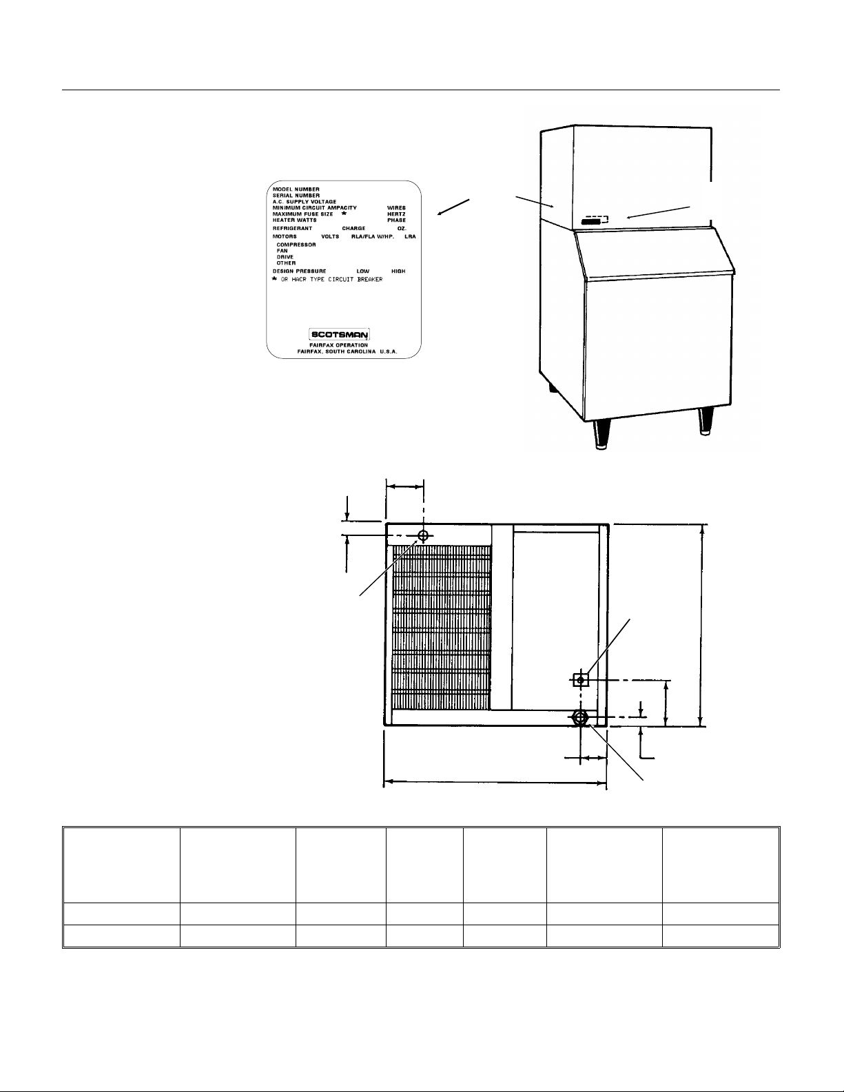
Specifications
Information regardin g Model Numb er, Serial
Number, Ampacity and Maximum Fuse Size are
located on the nameplate of the ice ma chine. The
model numbe r, serial number an d refrigerant
charge are also list ed on
the serial number plate
just behind th e fr ont
panel.
If recharging, always
use the charge listed on
the ice machine.
Nameplate
SLE300 Cabinet
Serial Number
Plate
3
⁄8"
1
Electrical
Inl et
3 3⁄4"
SLE300 Back View
(Air Cooled Model Show n)
Wate r
Inlet
1
4
20"
⁄4"
Specifi cations:
The SLE300 will stack onto a
variety of ice storage bins, see
sales literat ure for pro per ic e
22"
7
⁄8"
storage bin.
Model Number Dimensions
W" x D" x H "
Condenser
Type
Basic
Electrical
Minimum
Circuit
Ampacity*
Maximum
Fuse Size (or
HACR circuit
Refrigerant
Charge.
R-404A
breakers)
SLE300AS-1A 22 x 23 x 20 Air 115/60/1 17.3 20 15 ounces
SLE300WS-1A 22 x 23 x 20 Water 115/60/1 15.8 20 15 ounces
* Minimum Circuit Ampac ity is used to determin e
wire size and type per the Nationa l Elect ric Code.
January 1995
Page 2
Page 3
For The Installer: Environmental Limitations
The ice machine must be inst alle d ind oors in a
controlled environ ment.
Minimum Maximum
Air Temp 55
Water Temp 40
Water Pressure 20 PSI 60 PSI
Voltage 103.5 126.5
Operatin g the ice machine outside of the above
limitations, or outd oors, is pote ntially damag ing to
the machine, and it is misuse of the machine. This
may void the warranty.
Scotsman Ice Systems are designed and
manufactured with the highest regard for safety
and performance . They me et or exce ed the
standards of UL, NSF, and CSA.
Scotsman assu mes no liability or res po nsib ility of
any kind for pro duct s ma nufa ct ured by Scotsman
that have be en alte red in any way, including the
use of any part and/or other components not
specifically approved by Scotsman.
0
F. 1000F.
0
F. 900F.
SLE300
Scotsman reserves the right to make design
changes and/or improvements at any time.
Specifications and design are subject to change
without notice.
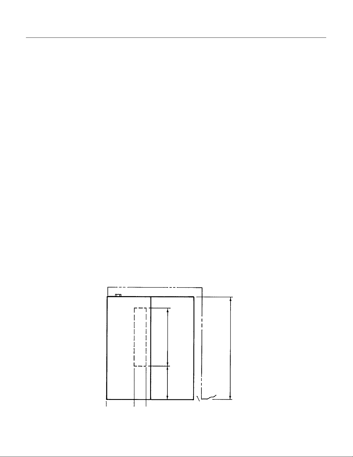
Airflow on air coo led models is :
••Intake thro ug h the right side grill.
••Ex ha u st throug h the back.
Dashed Lines Sho w
Outline of Ice Drop
Area.
Bin Control Mounts to
Right of Ice Drop Area.
7"
3"
6
12"
1
⁄2"
SLE300
Top View
23"
Do not install where this air flo w is obst ruc te d.
6" Space Required for
Air Flow (Air Cooled
Only) and Util it y
Connections
January 1995
Page 3
Page 4

SLE300
Installation
Water
The water supply for this ice machine has been in
contact with man y mat eria ls s ince it fell fro m the
sky as rain. All rain is slightly acidic , and tends to
dissolve the mat eria ls it come s in con tact with .
During water’s journ ey to the ice machine, it has
flowed ove r and thro ugh th e gro und, been pick ed
up by a municipal or priva te pump, fo rced thro ug h
a series of pipes of diffe ring construction and may
have been treated by the municipality providing
the wat e r.
The water supplied to this ice machin e will then
contain a variety of substances th at will likely show
up as solids during the ice making process. These
solids are similar to those found when water is
boiled out of a saucepan. Only the water boils
away, and t he minerals th at were in th e w ater
solidif y in the pan. Durin g ice making only the
water is frozen into ice, the minerals stay behind in
the reservoi r. This machine drain s ou t some of the
the water in the reservo ir eve ry cycle to minimize
the amount of minera ls in th e water syst em, but
after time the minerals will appear and have to be
dissolved by ice machine cleaner, the n flu shed
away during the clean ing proc ess .
Location
This ice machine may be installed in the open or
under a counter. Clearance may be req uire d at the
sides or top beyo nd what ’s nee ded to place the
cabinet into posit ion. Air co oled mod els take air in
the right side and exhaust out the back. Sp ace is
required for utilit y con nections at the back.
The ice machine is NOT designed for outdoor
use. It must be installed indoors, in a
controlled environment. The air and water
temperatures must not exceed rated limit s.
Pre-installation:
1. Inspect the place where the ice machine is to be
installed . Check fo r:
••space for the cabinet,
••water supply,
••drain av aila bilit y
••and electrical power su pply.
No extension co rds are allowe d. The buildin g dra in
inlet must be lower than the drain outlet of the ice
bin. The wate r sup ply mus t have a ha nd shu t of f
valve accessible when the unit is installed.
An ice machine is a food manuf act urin g pla nt ; it
takes a raw material, in this case water, and
transforms it into a food produ ct , ice. The purity of
the water is very import an t in obta inin g pure ice
and in maximizing product life .
The water to the ice machin e sh ould be filte red .
Water filters vary greatly in ability and functio n.
Install one that filte rs out suspende d solids to a
dimension of 5 microns or less . The fine r the filte r
the better , but finer filters may plug-up sooner than
course on es. It may be necessary to add a course
filter ahead of the fine filte r to prolong filter life.
Polyphosphat e feed ers are usually ef fect ive in
many water conditions.
Have the water teste d. Acid ic wate r or alka line
water will both cause corro sion . Disso lve d solid s
cannot be filtered out. Softened water is not
recommended . Neve r use de-ionized water.
Reverse-os mosis wate r must be treate d with
bufferin g agen ts befo re us e in the ice mac hin e.
Check with a water treatment specialist regarding
testing , tre atment and filters.
January 1995
Page 4
Page 5
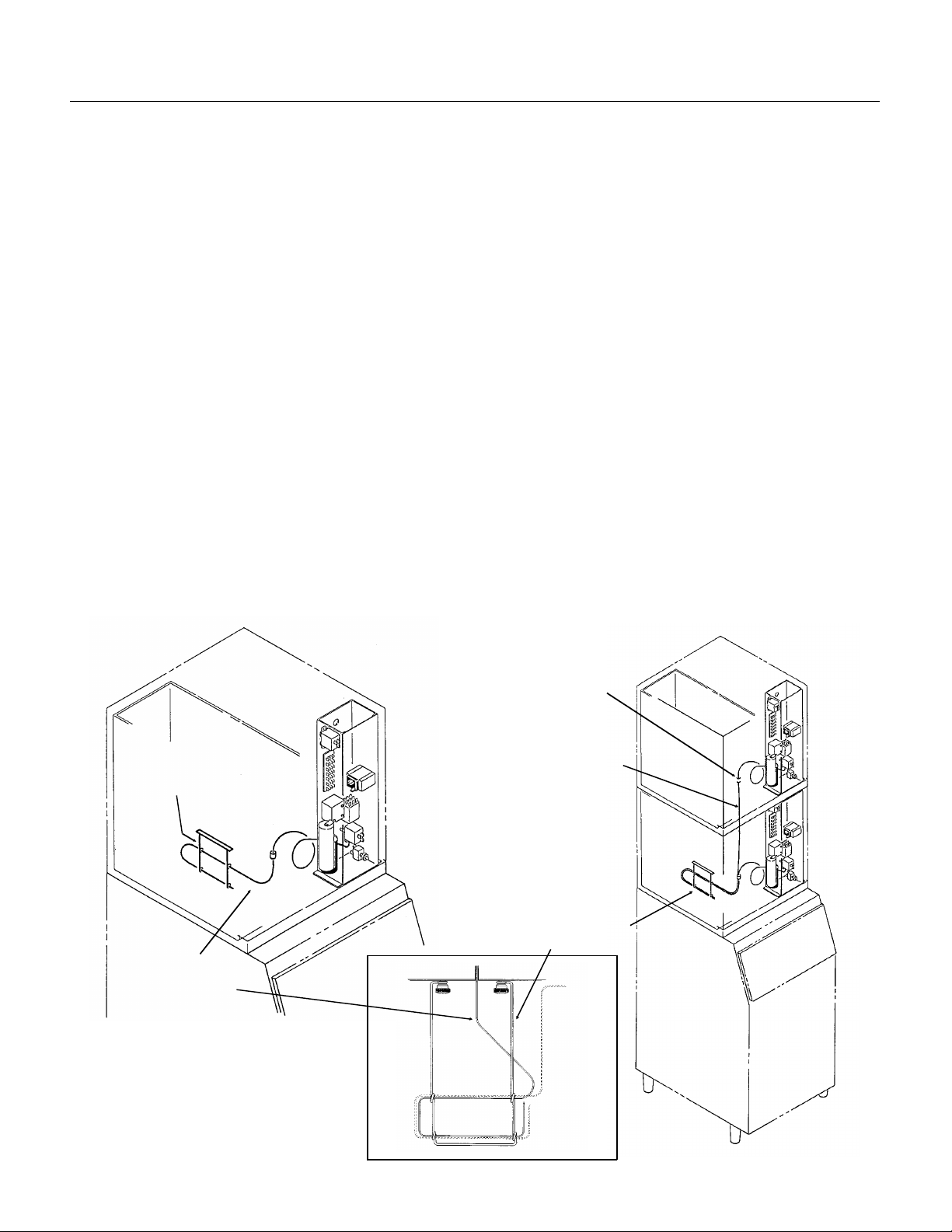
Stacking
Installation: Ic e Storage Bin
Thermostat
Capillary Tube
SLE300
Assembly:
1. Attach the legs, or optional casters, onto the ice
storage bin. Units th at are st ack ed shou ld only use
legs, not casters.
2. Be sure that the top edge of the bin has a good
gasket on it.
3. Place the ice machin e onto the stora ge bin.
4. Line up the ice machin e, check th at there is a
good seal betwee n the ice mac hin e and th e
storage bin.
5. If on a Scotsma n bin , at ta ch the ice mach ine to
the bin using the stra ps and bolt s ship pe d with the
ice machine. Drill two 1/8" holes in the back of the
bin and secure with sheet metal screws provided.
If on another brand bin, fo llow th e direct ion s
included with that bin.
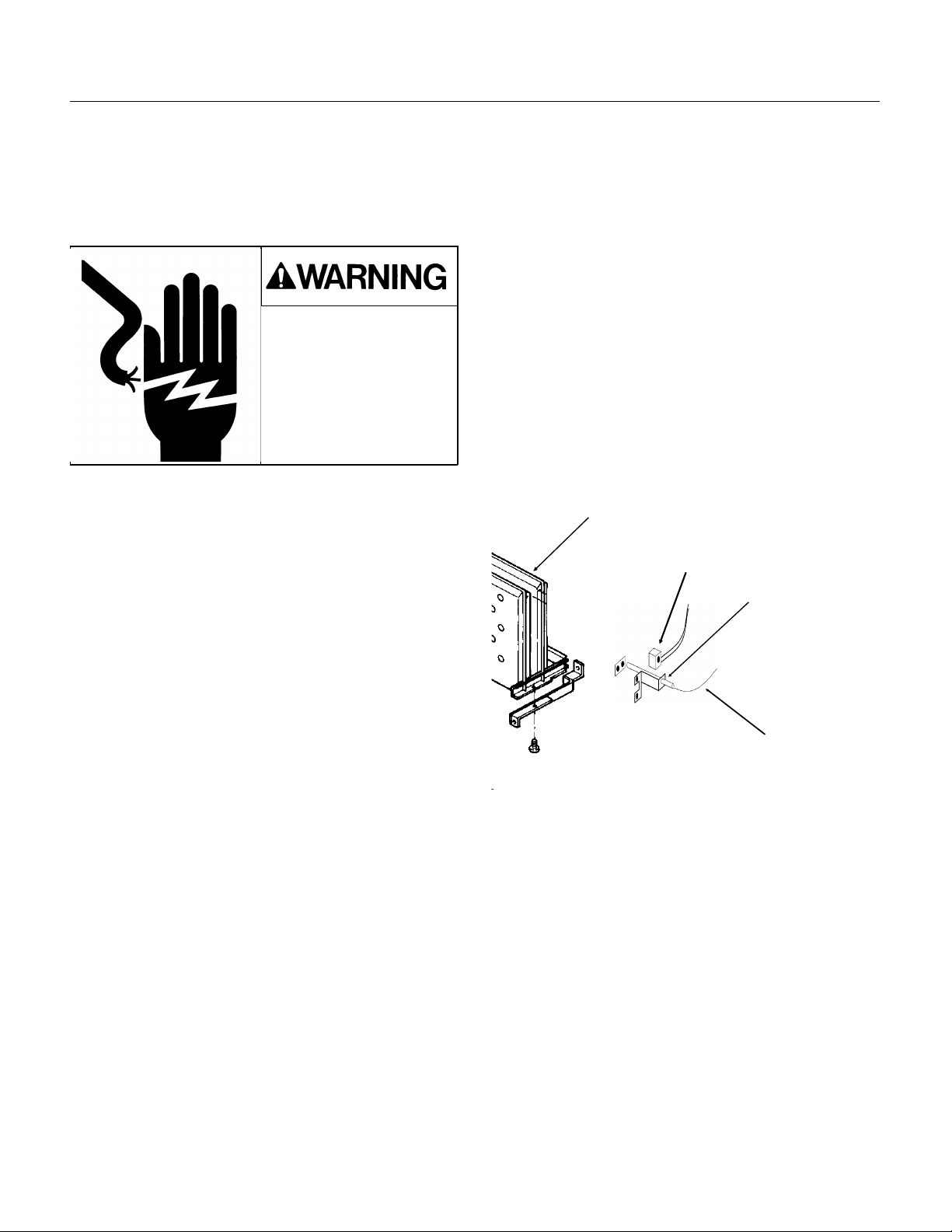
Bin Thermostat Installation:
1. Remove thermo sta t bra cke t fro m pac kage.
2. Attach the bin thermostat bracket to the bottom
of the ice machine usin g the thumb sc rews
provided. The re are pre-d rilled and tapped holes
located just to the right of the cube drop area.
Stacking:
This machine will stack onto any SLE300 or
SLC400. Note : Do not us e cas ters wh en sta ckin g.
1. Remove and discard the left top panel from the
lower unit.
2. Rem ove knock ou t plug from t op right panel.
3. Place gaske t mat eria l around the top of the
bottom uni t’ s cabinet & evapora to r compartment.
4. Carefully lif t the uncrat ed top unit onto the
bottom unit. Use of a mechanical lift is
recommended for this step.
5. Align the two ice maker cabinets.
6. Secure the top unit to the bott om one with the
hardware and st rap s ship pe d with the upper
machine.
7. Locate and uncoil all of the bin thermo st at
capillary tube .
8. Route the bin thermostat capillary tube from the
upper unit, through the hole in the base, through
the lower unit and into the bin thermostat bracket.
Discard upper unit brac ket .
Bin Thermostat
Bracket
3. Locate and uncoil a portion of the
bin thermostat capillary tube. Route
the end of the capillary tube into the
plastic tube in the base of the ice
machine (next to the comp ress or) and
through the bin thermostat bracket.
Note: SLB150: Use thermostat
bracket packed with that bin.
Bin Thermostat
Installation
Routing Hole
Capillary Tube
Fasten Cabinets
Together At Back
With Straps &
Screws.
Bin Thermostat
Bracket
January 1995
Page 5
Page 6
Bin Thermostat Capillary
Tube Installation
SLE30 0
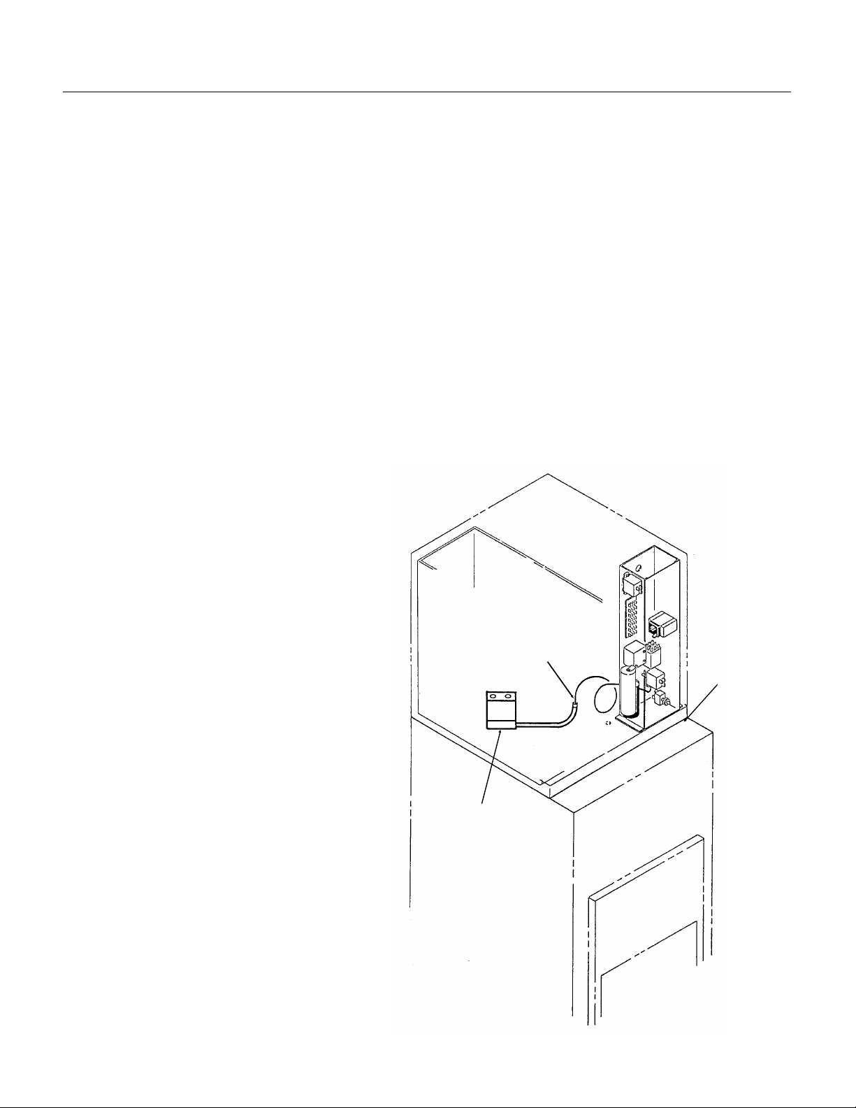
Installation: SLD150 Hotel Dispenser
Assembly
The ice machine must be pla ced ont o the top of
the dispenser, an d the bin thermostat capillary
tube routed into the bracket in the dispenser.
1. Check that the dispenser has a gasket all
around the perimeter of the top, 22" wide by 23"
deep.
2. Locate the inlet hole of the thermost at bracket ,
and make sure that it is open.
3. Place a corner post from the ice mac hin e cart on
at the front of left and right sides of the hotel
dispenser top.
4. Use a mechanica l lif t and pla ce th e ice ma chin e
onto the dispenser. The cardboard corner posts
should kee p the fro nt edg e of the ice mach ine up.
5. Remove the front panel of the ice machine.
6. Locate the bin thermostat capillary tube and
unc oi l about 18" of tub ing.
7. Locate plastic tube in base of ice
machine, next to compressor and
push the end of the capillary tu be thru
the tube, watch the capilla ry as it
comes out of the base, line it up with
the inlet hole of the thermosta t
bracket an d push it into the hole.
Move the cab ine t of the ice mach ine
until the capillary tube is going
straight down into the inlet hole.
8. Carefully remove the corner posts.
9. Push the capillary tube into the
thermostat bracket tube until abou t
14" of capillary tube is in the tube.
9 Remove the hardware package
from the mach ine , remove brackets.
10. At the back of the dispenser,
fasten brack ets to the ice machin e.
1 1. Using bracke ts for te mpla tes, drill
1/8" holes into the back of the
dispenser.
Route Capillary Tube
Through Plastic
Tube In Base
Bin Thermostat
Bracket Mounted In
Dispenser
Temporarily
Support Machin e
With Corner Posts
To Observe Cap
Tube Installat ion
12. Secure bra ckets to the dispenser
with sheet metal screws from the
hardware packa ge.
13. Follow other ins tallat ion
instructio ns from the SLD150.
January 1995
Page 6
Page 7
Installation: Sc ot sman IS or RS Dispens e r
RS or IS
Dispense r
SLE300
Assembly:
The assembly of the ice machin e onto the
dispenser requires two addit ion al parts: an adapte r
kit and a thermostat stand off kit.
1. Mark two spots on the inside left liner of the
dispenser: 2" down fro m the top, 4" from the back,
and 4" apart.
2. At the two marked spots , drill two 1/4 " holes thru
the plastic liner only.
3. From the stand off kit, locate the stand offs and
plastic anchors. Thread the stand offs partially into
the plastic anchors.
4. Push the anchors/stand offs into the holes.
5. Screw the stand of fs all th e way into the
anchors. Be sure th at the hole s in the stand offs
are horizontal.
6. Place a bead of silastic (from the kit) aro und the
stand off s.
7. From the adapter kit , pla ce th e st ain less stee l
adapter onto the top of the dispenser. Follow all
directions included with the kit.
8. After the ice machine has been placed on the
dispenser, remove the front panel and uncoil all of
the bin thermostat capillary tube.
9. Route the capillary t ube thru th e front hole in the
base of the ice mac hine, to the left side if the
dispenser towards the stand offs.
10. Route the end of the capillary tube thru th e
stand offs, bend the tube around the stand offs so
that it does not fall off.
1 1. Check that th e routing of the capilla ry tube is
away from the ice chute and up high near the base
of the ice machine.
Installation of Bin Thermostat
Capillary Tube
K1 Kit Adapter
Stand Offs From Kit K6
Drill 2 Holes For
Stand-Offs:
2" From Top Of
Dispenser &
4" From Back &
4" Apart
Route Capillary
Tube Through Front
Plastic Tube
Route Capillary
Tube Through
Stand Offs
January 1995
Page 7
Page 8
SLE300
Installation
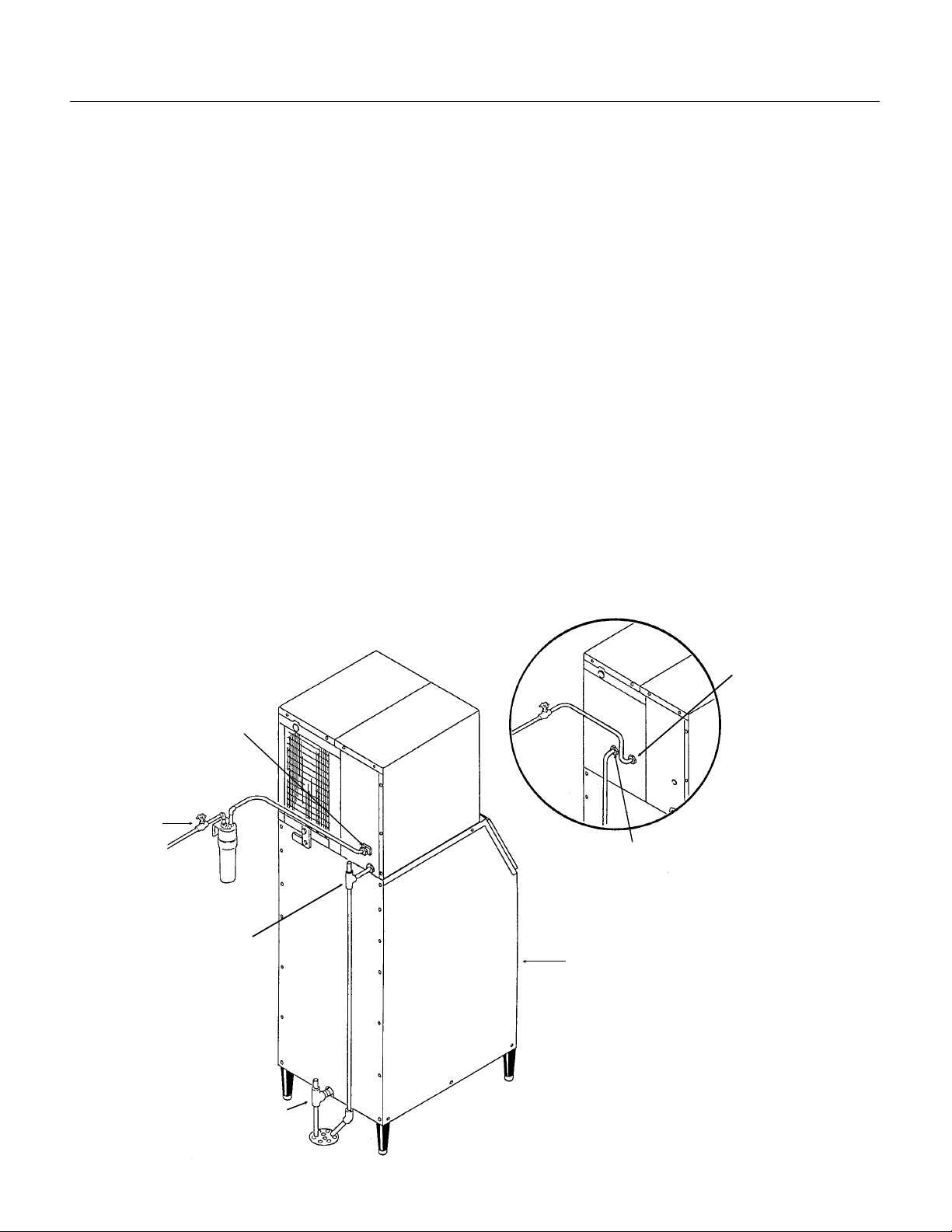
For The Plumber
Supply:
Screw the 3/8" male fla re (fit tin g sh ipped in
package insid e cabinet) into the 1/4" FPT fitting at
the ba c k of the cabi net (thread tape
recommend ed). Con ne ct co ld pota ble wate r to th e
water inlet. A hand shut of f va lve fo r inlet wate r
should be insta lled near t he mach ine . A wat er filt er
is recommended. Flush the water line prio r to
connect ing to the ice machine.
If water cooled , con nect a separate water inlet line
to the water cooled condenser inlet fitting. It should
also have a hand shu t off valve.
Drains:
Connect a drain tube to the reserv oir dra in fit tin g at
the back of the cabinet. The drain tube from the
fitting mus t be run separa te ly fro m any ot her drain
tube. The reservoir drain is a 3/4" F.P.T. bra ss
fitting.
Drain tube material must be rigid and meet local
code.
Traps in the bin drain line without vents ahead of
them will cause poor draining.
The bin drain mus t be vented if the re is a lon g
horizontal run (5’ or more). The reservoir drain
mus t be vented and not connected to th e bin
drain. All drains are gravity, and must have a
minimum fall of 1/4" per foot of horizon tal ru n.
Wate r Coole d: The wat er cooled condenser drain
is not vented, and is routed separately.
Maintain th e air gap req uire d by local co de
between the end of the drain tubes and the
building drain rec epta cle.
Note: Drain tu bin g sh ou ld be insulated to prevent
condensation from forming on the tubing.
CONFORM TO ALL LOCAL CODES
3/8 Male Flare
Water Inlet
Water Shut
Off Valve
Reservoir Drain
3/4" FPT, Must Be Vented.
Bin Drain. May Be Routed F rom
The Bottom On Some Model
Bins. Fittin g May Be Plastic.
DO NOT OVERHEAT.
3/8" FPT Inlet
Water Cooled
Condenser Plumbing
Connections
1/2" FPT
Outlet
Ice Storage Bin
(Typical)
Water Supply and Drain Con necti on s
January 1995
Page 8
Page 9
Installation
SLE300
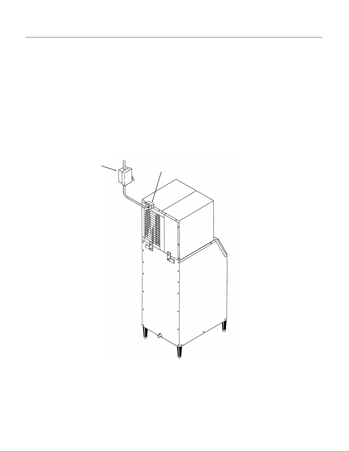
For The Electr ic ia n
This unit must be on a separat e 115 volt AC 60
cycle single phas e power sup ply. The maximum
fuse size for this circuit is listed on the name plate ,
and per th e nameplate use fuses, or HACR circuit
breakers.
To make the electrical connections:
1. Remove the right top panel.
2. Remove the junction box cover .
3. Make the electrical connections to the wires in
the junction box. A ground screw is provide d in the
junction box.
Hand Disconnect Switch
Junction Box
Follow All Local Codes - This Unit Must Be
Grounded. Usually a licensed electrician will be
required to connect th e elect rical se rvice .
January 1995
Page 9
Page 10

SLE300
After Utility Connections
1. Level the cabine t, use the leg leve lers on the
end of the legs to adjust the ca binet height. (Legs
should have be en installed when the bin was
unpacked) .
2. Wash out the bin. If desired, the interior of the
bin could be sanitized.
Final Che ck List
1. Is the ice maker cabinet in a roo m where
ambient temperature s are within the minimum and
maximum temperat ure s specified?
2. Has the water supply been connected?
3. Is the wa ter pressure adequate?
4. Have the water connections b een checked for
water leaks?
5. Have the drain con nections been made?
6. Have the drain connections been checked for
leaks?
7. Is the cabinet level?
8. Is the ice machine connect ed to a 1 1 5 volt
electrical power supply and is the ice machine the
only load on that circuit?
9. Has all of the shipping material been remov ed
from the inside of the cabinet?
10. H as the bin and cabinet been wiped clean and
sanitized ?
11. Has the Customer Evaluation & Warranty
Registration form been properly fille d out? Check
for correct mod el and se rial numbe rs f rom the
nameplate, then mail the comple te d form to
Scotsman .
12. Has the owner/u ser been give n the name and
telephone number of the au thorized Scotsman
Service Agency serving that location?
January 1995
Page 10
Page 11

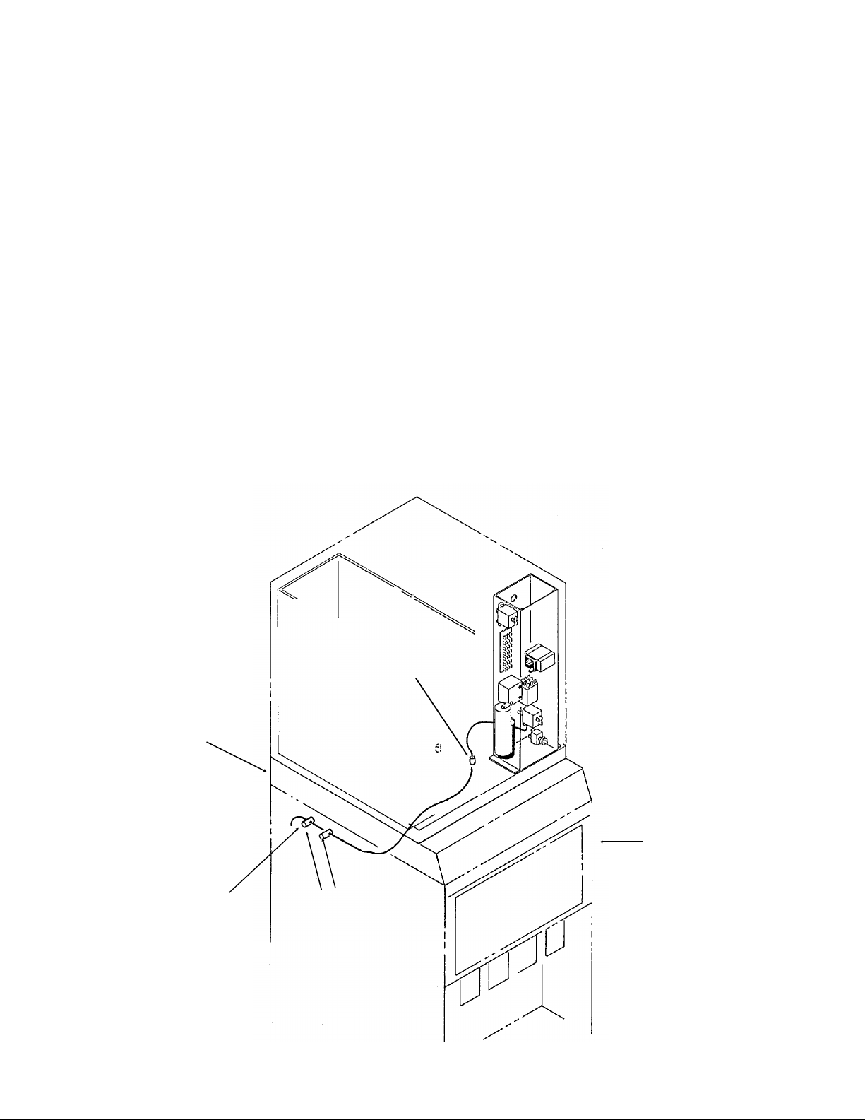
Component Location
ICE/OFF/WASH Switch
Bin Thermostat
Control Box
Many components are serv icea ble from th e front
without removin g the side panels .
SLE300
Behind the front panel:
•• Water pump
•• Inlet water va lve
•• Reservoir
•• Evaporators
•• Water distributor pan
•• Ice size control adjustment
•• ICE/OFF/WASH switch
•• Control box
Ice Size
Thermostat
Compressor
Relay
Ice Thickness Contro l
Control Bo x Detail
High
Pressure
Cut Out
Harvest
Relay
Bin
Thermostat
Ice/Off/Wash
Switch
Water Distributor
Pan
Bin Thermostat
Bracket
Water Inlet Valve
& Strainer
Water Pump
Drain Elbow
Componen t Locati o n
January 1995
Page 11
Page 12

Correct Size &
Shape
Cube Size Diagram
Set
Screws
SLE300
Initial Start Up
After the final check list has been gone through,
the ice machine may be started up.
1. Open the water sh ut of f va lve; the inlet wate r
valve will open, and water will flow into the
reservoi r..
Ice Thickness
Probe Adjustment
2. Switch on the electrical power.
3. Remove the front panel.
3. Locate the I CE/OFF/WASH switch, switch
Up for LARGER
Down for SMALLER
it to WASH.
4. The water pump will begin to pump water ove r
the ev aporator s .
5. Allow the reservoir to refill. Norma l water leve l is
1/8" below the high point of the lowe r curve of the
sip hon u-tub e.
6. Switch the ICE/OFF/WASH switch to OFF.
7. Check the action of the siphon. The water level
in the reservoir sho uld drop to the bottom curv e of
the U-bend (normal water level) in about 2
minutes. If not, check for proper drain tube
connections.
Ice Size Adjustment
Plate:
Cubes Too
Thick
8. Switch the ICE/OFF/WASH switch to ON.
9. On air cooled models the fa n motor will beg in to
turn, and warm air will be discharged from t he
back of the ice machine .
On water cooled models warm water will begin to
flow from the conden ser dra in.
10. The water temperatu re in the res ervo ir will
soon b e 32
0
F., and ice should begin to form on the
evaporato rs.
1 1. Allow the ice mac hine to operat e for abo ut
15-20 minutes . The ice sho uld be fully f orme d and
should be harvested within a few minutes.
12. After harv est , ch eck the ice cub e size .
Compare a fresh cube to the diagram on the
back of the front panel. If needed, adjust the
cube size by loosening the two set screws and
moving the ice thickness probe plate.
Move the plate down for smaller cubes and up
for larger . Re-tighten set screws.
For proper operat ion , th e ice thick ness sho uld be
11
set to the 1
⁄16" diameter.
The machine is designed to harvest cubes of
only the correct thickness.
1 11⁄16"
Cubes Too
Thin
January 1995
Page 12
Page 13

Initial Start Up
SLE300
Note: If the fi rs t ba tch of cu be s are not all un ifo r m
discs, some ice machin e cle an er sho uld be added
to the reservoir.
1. After ice ha s been harvested, but be fore new
cubes begin to form, switch the ICE/OFF/WASH
switch to WASH.
2. Add 4 oz. of ice machine cleaner to the
reservoi r. Allow unit to operate that way fo r 10
minutes.
3. Switch ICE/OFF/WASH switch to OFF
4. Shu t the water supply of f.
5. Remove the splash guard, and drain the
reservoir by removing the drain elbow.
7. Replace all parts, turn on the water and move
ICE/OFF/WASH switch to ICE. The next batch
of ice should be uniform.
13. Check harvest. The machin e will have to
harvest all of the cub es befo re it go es back into the
freeze cycle.
14. Check operation of the bin co ntrol circu it by
holding ice on the bin control tu be in the bin.
If the ice maker does no t sto p with in 1 minute ,
while keeping ice on the th ermostat, rotate the bin
thermostat shaft counter clockwise until the ice
maker does stop. Remo ve the ice from th e
capillary tube; the ice make r sho uld resta rt with in 2
minutes. If it do es not, rotate the adjust ing shaf t
clockwise until the machines starts.
15. Replace all the panels. The ice machine is now
ready for automatic operation.
Siphon Tube Schematic
U-Tube Adjusted
Here = No Purge
Siphon Breaker Hole
U-Tube Here =
Maximum Purge
Water Level
At Harvest
Water Level With
Pump ON
Water Inlet
1/8 - 1/4
Drain Outlet
Elbow
Bottom of
Reservoir
January 1995
Electrical Sequence:
Freeze Cycle:
During the first part of the free ze cyc le, the ice
machine comp res sor, fan motor if air coole d, and
water pump are operat ing.
Assume the bin thermo stat is open (low ice), relay
K1 will NOT have power thru its coil and K1
contacts 6-2 will be closed, connec tin g power to
the ice size thermosta t.
The ice size thermostat con tact 2-3 are clo sed,
connecting power to the fan and pump motors.
The Harvest Termin ation Thermo st at is closed to
NC, but there is no power thru it.
The ice size thermostat heater is on, and the
compressor contactor coil is energized.
Harvest:
In the harvest cycle , th e compressor is operating,
and the hot gas valve is energized . The wate r
pump is off, and air cooled mod els swit ch the fan
off.The bin thermo stat is still open .
When the ice near the ice size thermo sta t se nsin g
tube grows large enough to force water over the
sensing tu be , th at tub e loo se s hea t, and at 38
contact s 2-3 ope n and 2-1 close.
This removes power from the water pump and fan
and connects power to the defrost relay coil. Whe n
the relay coil has power, it connects power to the:
••Hot gas valve coil
The harvest termination switch is closed, an d
power flows thru it to the defrost relay coil. This
keeps the relay energized, even when the ice size
thermostat switch es cont act pos itio n as a result of
ice falling away from th e sensin g tube .
The unit stays in the harves t cycle until the
thermodisc on the suctio n line warms up to 55
at that time the defrost thermodisk switches to NO
and the harvest cycle is termin at ed. If the bin
thermostat is still open, relay K1 will st ill not have
power and the unit will go back into the freeze
cycle. If rela y K1 has power, it shuts off th e ice
machine by cutt ing power to the ice size
thermostat and contactor coil.
The ice size thermostat heater is on.
Whenever there is ice on the bin thermostat, it
closes a circuit to the coil of relay K1 and stops the
ice making process at the end of a harvest cycle.
Page 13
o
F.
o
F.,
Page 14

SLE30 0
Maintenance, Cleaning and Sanit izing
Cleaning Schedule:
••Scrub the outside of the cabinet once a week
wit h soa p and water.
••Sanitize the bin interior once a month.
•• Clean the water system and air cooled
condenser a minimum of twice per y ear. If in an
area of high mineral con ce nt rat ion in the wate r
supply, clean wate r syst em 4 times a year.
Air Cooled condenser (air cooled only):
Remove th e right side pan el.
The air flow thru the cond enser is fro m f ron t to
back, so dust will build up on the fan side of the
condenser fin s.
The fan motor, bracket and part of the shroud may
be removed as an assembly:
1. Unplug the fan motor.
2. Remove 3 screws at the righ t edge of the fan
shroud.
3. Pull the assembly out th e right side . The
condenser fins are then visible for cleaning.
The fins of the condenser will become fo ule d with
dirt, and must be cleaned. A vacuum cleaner with
a soft brush attac hme nt will extrac t most loose
dust stuck to the surface of the condenser fins..
Water cooled un its:
The water cooled condenser may, over time and
under certain water conditions, become internally
restricted by minerals. Thes e will have to be
dissolved by acid or the condenser replaced. Only
a qualified service agent should att emp t th is type
of service.
Ice Storage Bin
The interior liner of the bin is in contac t with a food
product : ic e. The storage bin must be cleaned
regularly to maintain a sanitary environment.
Once a week cleaning with soap and water, a hot
water rinse and an air dry is a basic procedure.
Every 30 days, the liner should be sanitiz ed with a
commercial ice machine san itize r, according to the
direction s of the sanitizer, or with a solu tio n of
household bleach a nd water:
1. Mix the bleach and water using the ratio of two
ounces of blea ch to two gallons of water.
2. Wipe all interior surfa ces of th e ice storage bin
with the bleach and water.
3. Allow t o air dry.
T o Re move Scale:
1. Mix a cleaning solution of 4 ounces of Scotsman
Ice Machine Cleaner to 4 pints of warm
0
F.-1100F.) water.
(95
2. Using rubber gloves, dip a nylon scouring pad
into the clean ing solut ion and scrub the scale off
the liner .
3. After the scale ha s been remove d, rinse all
surfaces inside the bin with clean, potable water.
Stainless Steel Bin Liner
The stainless ste el line r of th e bin will require
periodic cleaning. Chemicals in the water suppl y,
such as chlorine, cause bro wn stains to appear on
the surface of the sta inle ss ste el pa rts .
1. General Cleaning - staining is usually remov ed
by washing the parts with ordinary cleanin g
powder such as Bon-Ami or Copper-Glo and
water. After cleanin g, rin se with clea r wate r.
2. Water tre atment. The chlorine enters the
machine fro m the municip al water supply . It can be
removed from the wate r supply by us ing a
charcoal or ac tiva te d carbo n wat er filt er to trea t th e
water to the ice machine. If staining is severe,
filters of this type are recommended.
Exterior Cabinet Cleaning:
The exterior cabinet may be cleaned by scrubbing
with soap and water. Do not use cleane rs
containing petroleum products.
A nylon type brus h may be used to scrub stubbo rn
deposits.
January 1995
Page 14
Page 15

Cleaning: Ice Machine Water System
Dissolve and Remove Minerals:
SLE300
1. Remove front panel.
2. Move the ICE/OFF/WASH switch to OFF.
3. Remove the splash guard.
4. Shu t the water supply of f.
5. Drain the water from the sump by removing the
drain elbow.
6. Disconnect hose from the wat er dis trib ut or pan,
and remove the water distrib utor pa n.
7. Mix a solution of 5 oz . ice mac hin e clea ne r and
1 gallon of warm (95
Scotsman Ice Machine
Cleaner contai ns acids.
These co mp ou nd s may
cause bur ns.
If swallowed, DO NOT
induce vomiting. Give
large amounts of water or
milk. Call Physician
immediately. In case of
external contact, flush
with water.
KEEP OUT OF THE
REACH OF CH ILDR E N.
8. Wash the splash guard, drain elbow and water
distributor pan with the ice machine cleaner/water
solution.
9. With the solutio n of ice mach ine cleaner and
water, wash the refrigerat ion tub ing , line r,
evaporato rs, su pport brack et s and the water p ump
assembly. Use the brush an d/ or a cle an cloth .
10. Replace th e dr a i n e lbow .
1 1. Open the wat er sup ply and allow the sump to
refill.
12. Add 5 oz. ice mac hin e clea ner t o the su mp
area.
13. Replace th e water distributor pan and splash
guard. Be cert ain the hose to water dis trib ut or pa n
is connected to pan.
14. M ove the ICE/OFF/WAS H swit ch to wash and
allow the solutio n to circula te for 15 minut es, then
mov e the ICE/O FF/WA S H swit ch to OFF.
o
F. - 115oF.) water.
17. Remove the splash guard.
15. Shut the water supply off.
16. Drain the water from the sump by remo vin g the
drain elbow.
Sanitize:
17. Remove the water distrib ut or pan.
18. Mix a sanitizer solutio n of 1 ounce of
household bleach to 2 gallons of warm (95
o
F.) water
115
19. Wa sh th e sp lash gua rd and th e wat er
distributor pa n with the solut ion of sanit izer. Allow
to air dry.
20. With the sanitizer solution, wash the
refrigeration tubing, liner, evaporators, support
brackets and water pump assembly; use the brush
and/or a clean cloth.
21. Replace th e water distributor pan and splash
guard. Be certain that the hose to the water
distributor pa n is tightly connec ted to the pan, and
that the flow washer in the hose is not in sideways.
22. Replace th e dr a i n e lbow .
23. Add ice machin e sanit izer so lution to the sump
area until it is full.
24. M ove the ICE/OFF/WAS H swit ch to W ASH
add more sanitizer solu tio n to the sump area until
it is full again.
25. After 5 minutes, move the ICE/OFF/ WASH
switch to OFF.
26. Remove the splash guard.
27. Drain the water from the sump by remo vin g the
drain elbow.
28. Replac e the dra in elbow and splash guard
29. Open the water supply an d allow the sump to
refill.
30. M ove the ICE/OFF/WAS H swit ch to ICE.
31. Replace the front panel.
32. Discard first batch of ice and all other batch es
until all traces of cle aner and sanitiz er disappear.
o
F. -
January 1995
Page 15
Page 16

Fan Motor
(On)
SLE300
Refrigeration Schem atic :
Freeze Cycle:
From the compresso r, hot discharge gas is
pumped to the conde nse r, either air or water
cooled.
At the cond enser, he at from the refrigerant flows
into the cooling med ium, eith er air or wat er, and
the refrigeran t co nden ses into a liquid . From the
condenser the liqu id ref rige ran t flo ws th rou gh the
liquid line to the metering device - a thermostatic
expansio n va lve.
At the expansion valve , th e liqu id ref rige ran t
passes fro m a high press ure zone to one of
relatively low pressure, and in the low pressure
zone it evapora tes. The low pressure zone where
the refrigerant evaporates is the evapora to r. When
the refrigeran t ev apora te s, it abso rbs he at from th e
metal parts of the evapo rat or an d the water flowing
over it.
From the evaporator, the refrigerant flows back to
the compresso r through the suction line.
Water Schematic:
Wate r flows int o the ice machin e fro m its inle t
connection at the back of the cabinet, through the
inlet water va lve and int o the res ervo i r. The water
in the reservoi r is pump ed up and th rou gh the
water distrib ut or tube at the top of the evapora to rs.
From there, the water flo ws over bot h sides of the
evaporators and back into the reservoir.
Melted ice and water spills into the bin flow
through a drain in the base of the bin to the
exterior drain connection at the back of the cabinet .
Evaporators
Inlet Water
Valve
Float
Valve
Water Distribution
System
Water
Pump
(On)
Thermostatic
Expansion Valve
Suction Line
Hot Gas Valve (Closed)
Discharge Li ne
Condenser
Compressor
Dryer
Water Reservoir
Siphon
Tube
Refrigeration Schematic
January 1995
Page 16
Page 17

Harvest Cycle:
Condenser
Compressor
Refrigeration Schematic
Fan Motor
(Off)
SLE300
The ice maker con tin ure s to fre ez e the wat er int o
ice unitl the ice next to the ice size thermostat
probe has become thick enough to force wate r
over the pro be. After the cold water has red uced
the temperature of the probe to 38
o
F., the ice size
thermotsta t will switch the machin e into the harve st
cycle.
During the harvest cyc le, the refrig era nt flows from
the condenser, through the discharg e line to a
branch in the line cont ain ing the Hot Gas Va lve .
This valve is Open during the harve st cyc le,
allowing the hot discharge gas to bypass the
condenser and enter the evapo rat or at its inlet .
The hot discharge gase s warm up the ev apora to r
enough to allow the surf ace of the ice froze n to the
evaporator to melt. The remain ing ice will then fall
off into the bin .
Water Distribution
System
During the Harvest Cycle, the water level rise s,
filling the reservoir ove r the siphon tube and
siphoning some of the res ervo ir wate r out to the
drain.
The harvest cycle continues until the suction line
warms up e nough to cause th e harvest termination
thermost at to switc h the machine bac k into the
freeze cycle.
Evaporator s
Inlet
Water
Valve
Water Reservoir
Water
Pump
(Off)
Sipho n
Tube
(Draining)
Thermostatic
Expansion Valve
Suction Line
Hot Gas Valve (Open)
Discharge Li ne
Dryer
January 1995
Page 17
Page 18

SLE300
Technical Charact eris ti cs
Typical Cycle Time
••18 minutes @ 90
Typical Harvest Ice Weight
••2.8 - 3.2 pounds
Typical Low Side Pressure, 8 minutes into freeze
••20 PSIG @ 70
••26 PSIG @ 90
••42 PSIG @ 100
••22 - 27 PSIG for water cooled
Typical Freeze Cycle Discharge Pressure
••196 PSIG @ 70
••262 PSIG @ 90
••350 PSIG @ 100
••270 for water cooled
o
F. air and 70oF. water; 15 minute s @ 70oF. air and 50oF. water
o
F. Air
o
F. Air
o
F. Air
o
F. Air
o
F. Air
o
F. Air
Refrigerant Charge:
••15 ounces R-404A
Harvest Time
••Normally 1
Typical Suction Pressure, In Harvest:
1
⁄2 to 2 minutes. Depends upon time required to warm suc tio n line to 55oF.
••
Typical Discharge Pressure, In Harvest:
••
High Pressure Cut Out
••Cuts out at 380 PSIG, reset s at 315 PSIG
Thermostatic Expansion Valve
••Superheat is 3
Bin Thermostat
••Cut In to shut OFF machine at 35
Ice Size Thermostat:
o
- 6oF.
o
F.; Cut Out to Start ma chin e at 39oF. Adjustable warme r.
•• Switches to harve st cyc le with temp eratu re fa ll to 38
oF.
Resets at 43oF.
Ice Size Heater
••Adds heat to ice size th ermo st at to preven t pre mat ure harv est. 6, 000 ohms resis ta nce .
Harvest Termination Thermostat
•• Switc hes from cont acts C-NC to contacts C-NO at a temperature rise to 55
Resets at 40
o
F.
January 1995
Page 18
o
F. (return to freeze or OFF).
Page 19
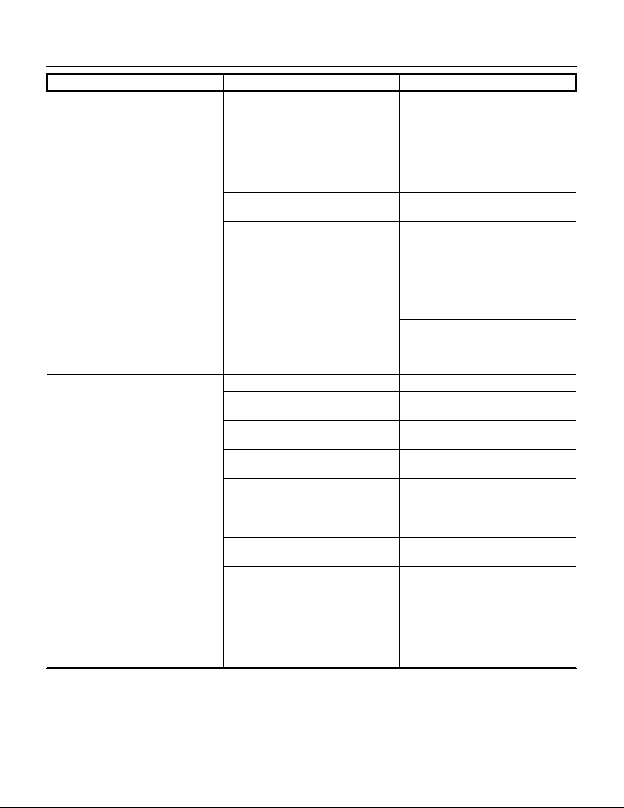
Service Diagnosis:
SYMPTOM POSSIBLE CAUSE PROBABLE FIX
No ice is made, nothin g opera te s Unit off, due to no power Restore po wer
Unit off, due to ICE/OFF/WASH
switch in OFF position
Unit off, due to bin thermo st at
closed
Unit off, due to relay K1 coil open. Check relay coil, if open repla ce
Water cooled unit off, due to high
pressure cu t ou t op en
No ice, compress or of f No cooling due to compressor not
operatin g
No ice is made, compressor is
operatin g
No water due to water turned off. Reconnect water supply
No water due to water f ilte r
plu gged.
No water due to strainer screen
plugged
No water due to inlet wate r valve
will not open
Water in reservo ir, bu t no water
over evaporators
No cooling at evaporator due to
hot gas valve lea king thru
No cooling at evaporator due to
fan not turning
Fan and pump do not have
power; hot gas valve opens and
closes.
No cooling at evaporator due to
dirty condenser
No cooling due to compre sso r n ot
pumping
Switch ICE/OFF/WASH switch to
ICE
Check temperature at bin
thermostat bracket, if warmer than
o
F., thermostat should be
40
closed. Adjust/replace thermostat.
relay.
Lack of water to condenser,
check water sup ply and wat er
regulating valve.
Check compressor for voltage,
continuity, and operation. Check
starting components. Replace if
found to be faulty.
Check temperature of
compresso r, if hot may be lack of
refrigera nt, defe ctiv e TXV or
compresso r
Replace wat er fi lt er
Clean out inlet screen
Replace valve
Water pump does not work,
replace pu mp
Replace ho t gas valv e
Check & replace fan motor.
Coil or relay open, rep lac e rela y.
Clean condenser
Check system pressures, replace
compressor if not pumping
SLE300
January 1995
Page 19
Page 20

SLE30 0
Service Diagnosis:
SYMPTOM POSSIBLE CAUSE PROBABLE FIX
No ice compresso r is operating No cooling due to low refrig era nt
charge
Ice is made, but not harvested. Ice size thermostat contacts do
not switch position
Ice will not slide down ice rack
due to minerals on rack.
Ice will not slide down ice rack
due to ice rack out of position
Ice will not slide down ice rack
due to bent ice ra c k
Lack of heat during harv est cycle
due to unit in air temp. less than
0
F.
55
Lack of heat during harvest due to
water flowing thru wate r coo led
condenser
Lack of heat during harvest due to
lack of refrigerant
Lack of heat during harvest due to
hot gas valve not opening fully.
Ice does not slide down face of
evaporato r due to mine rals on
evaporator surface
Harvest cycle too short du e to
harvest termina tio n thermo stat
opens at too low a temperature.
Locate leak, recover remaining
refrigera nt , rep lace drye r ,
evacuate and weigh in nameplate
charge.
Ice not made near thermo st at
probe due to water distribut or
holes restricted. Clean water
distributor pan.
Thermosta t de fective, replace it
Clean machine with ice mach ine
cleaner.
Reposition ice rack
Replace ice rack
Warm up air or move machine.
Replace water regulating va lve
Check low side pre ssu re du ring
harvest . If low eith er th e cha rge is
low or the hot gas valve does not
open fully. If charge is the
problem, locate leak, recover
remaining refrig era nt , rep air leak,
replace drie r, ev acu at e and weig h
in nameplate charge.
Check low side pre ssu re du ring
harvest . If low eith er th e cha rge is
low or the hot gas valve does not
open fully.
Clean water system with ice
machine cle aner
Replace harve st termination
thermostat
January 1995
Page 20
Page 21

SLE300
Service Diagnosis:
SYMPTOM POSSIBLE CAUSE PROBABLE FIX
Ice is made, but will not harvest Will not harvest due to hot gas
valve not opening.
Slow/incomplete harvest due to
hot gas valve not fully open.
Makes ice, but very litt le High discharg e pressu re, due to
dirty condens er; faulty fa n motor;
not enough water thru water
cooled condenser, high water
temperatures, water reg. valve set
too high.
Inlet water temperatures and
room ambient very high
Long freeze cycle due to hot gas
valve leakin g thru.
Compressor ine ff icie nt Check/re pla ce compressor
Cubes are wrong size/sh ape Ice size thermostat not adjust ed
properl y
Freeze cycle too sh ort due to
heat e r open
Water system is rest rict ed with
minerals
Ice thickness probe tube covered
with minerals
Not enough water Check water supply pressure
Too much superheat Check superheat, replace TXV if
Ice fused togethe r in bin Ice in bin too long Advise user to pour water on ice
Too many minerals in water Suggest water treatment to user.
Check for volt ag e to coil in
harvest , if th ere is voltage
replace ho t gas valv e
Check low side pressure in
harvest, replace hot gas valve if
too low with correct ref. charge.
Check for causes of high
discharg e pre ssu re and corre ct .
Advise user, sugg est additio na l
room cooling.
Check temp erature of tubes to
and from hot gas valve; th ere
should be a temp erature drop
across the valve in the freeze
cycle. Replace valve if temps are
nearly equal.
Adjust ice size thermostat; use
gauge shipped with machine
Check/re pla ce he at er on ic e size
thermostat probe tube.
Clean water system with
Scotsman Ice Machine Cleaner
Clean tube with ice machine
cleaner
Check water supply for restrictions
too hi g h.
Check hot gas valve for leak-thru;
replace if lea ks th ru.
to ease remova l
January 1995
Page 21
Page 22
SLE30 0
Removal and Replacem ent
Ice Size Thermostat:
Before replac ing the ice size thermostat , it should
be positively determine d that it is at fault.
1. Disconnect electrical power.
Electrical sho ck hazar d.
Electrical shock can
cause personal injury.
Disconnect power before
beginning to service
components.
2. Remove the front panel.
3. Remove the control box cover.
4. Locate the ice size thermostat.
5. Remove the two screws holdin g the cont rol to
the control box, and lift the con tro l out.
6. Pull the three wires off the posts of the ice size
thermost at.
Primary Resistor (Heater)
1. Disconnect electrical power.
2. Disconnect the primary resisto rs yello w wire
from terminal #4 and the white wire from te rmina l
#1. Pull the two wires out of the control box and
thru the insulated wall.
3. Mark locatio n of adju st ment bracket.
4. Remove two screws and the ice size thermo stat
probe tub e bra cke t.
5. Remove the evaporator side plastic sleeve and
heater from the tube.
6. Reverse the prio r ste ps to re pla ce . Pro be tub e
must be inserted into plas tic guide att ac hed to
evapora tor.
7. Place adjustmen t bra cke t in its origin al position.
Check ice size.
Evaporator
Heater
Probe Tube
& Bracket
7. Locate bulb on suction line.
8. Follow the capillary tube of the ice size
thermost at: th e end of the ice size thermostat is
inserted in a tube. Pull it out of the tube.
9. Pull the capillary tube of the ice size thermost at
thru the grommet in the side of th e contro l box .
10. Remove the ice size thermo st at from the
control box.
11. Replace the ice size thermo sta t with the prop er
part number, following the above steps fro m 1 0-1 .
Capillary
Tube
Replacement of Ice Size Thermostat
January 1995
Page 22
Page 23
Removal and Replacem ent
SLE300
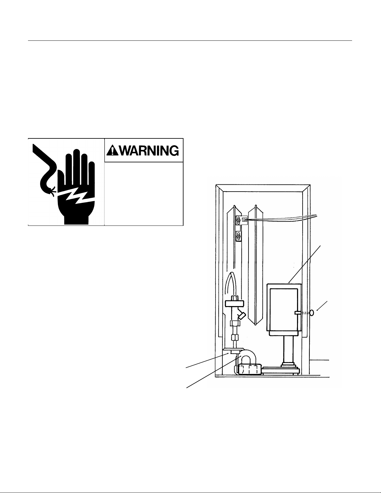
Water Pump
The pump provides the force to move the water
from the rese rvoir to the free zin g surface. The
pump does not need oil, but if it becomes noisy,
overheats, or will not pump it should be replaced.
Be certain to confirm electrical faults with a
voltmeter or ohmmeter before replacing th e pump.
The pump should be opera ting whenever the
machine is in the free ze cy cle.
1. Unplug or disconne ct the elect rica l powe r.
Electrical sho ck hazar d.
Electrical shock can
cause personal injury.
Disconnect power before
beginning to service
components.
Inlet Water Valve
The valve may plu g-up from minerals in the water,
and may be cleaned rather tha n rep lac ed.
1. Shu t off the wat e r supply.
2. Unscrew the fitt ing at the to p of the valve, and
pull the water inlet tube out of the valve body.
3. Remove the screws h old ing the valve brac ket to
the liner .
4. Remove the valve fro m the ice mach ine.
5. Reverse the abov e ste ps to reassemble.
2. Unplug the pump from its connection.
5. Loosen the two fasteners holding the cover to
the wall.
6. Remove pump cov er fro m the machin e.
7. Pull discharge hose fro m pump disch arg e port.
8. Remove pump from ice machine.
9. Reverse abov e ste ps to rep lace .
Float Valve
Siphon "U" Tub e
Pump Cov er
Thumb
Screws
Replacement of Water
Pump
January 1995
Page 23
Page 24

VAPOR V APOR
TEMP. PRESS. TEMP. PRESS.
(DEG F) (PSIG) DEG F) (PSIG)
-20 17 70 146
-18 18 72 150
-16 20 74 155
-14 21 76 161
-12 23 78 166
-10 24 80 171
-8 26 82 177
-6 28 84 182
-4 29 86 188
-2 31 88 194
0 33 90 200
2 35 92 206
4 37 94 212
6 39 96 219
8 41 98 225
10 43 100 232
12 46 102 239
14 48 104 246
16 50 106 253
18 53 108 260
20 55 110 268
22 58 112 275
24 60 114 283
26 63 116 291
28 66 118 299
30 69 120 307
32 72 122 316
34 75 124 324
36 78 126 333
38 81 128 342
40 85 130 351
42 88 132 360
44 91 134 370
SLE300
Removal and Replacement: Refrigeration System
This ice machine uses R-404 A (HP6 2) ref rige ran t and polyole ster oil. Do
NOT use mineral oil in this refrig era tio n syste m.
••R-404A is a "Near Aze otrope" so liquid charging is require d:
••When the system is serv iced , a specia l liquid line drie r is requ ired . It is
included with replacement compressors.
••HP62 is not comp atible wit h mineral oil, so th ese ice mach ine s use
Polyoles ter oil. Po lyole st er oil ab sorb s wat er very easily . When one of
these refrige rat ion systems is opened for service, it must be re-seale d
as soon as possible (15 minutes maximum).
••Special leak detec tio n equip men t is required to locat e small refrige ran t
leaks. Usua lly a lea k det ec to r capa ble of de tecting a Halongenate d
refrigerant or HFC-134a will work. Check with the leak detect or
manufactu rer if in doub t.
LIQUID CHARGING Instructions for R-404A
In preparation for charging, the low side hose should ha ve a sight glas s,
and/or a restrictor device (such as a "Charge Faster") installed in it for
metering liqu id int o the low side of the syste m.
1. After a thorough evacuat ion to at leas t 200 microns, shut of f the
manifold valves and switch off the vacuum pump.
2. Place a drum of R-40 4A ont o an elect ron ic sca le.
3. Attach the chargin g hose to the drum.
4. Open the valve on the drum and purge the chargin g hose.
5. Zero out the scale.
6. Shut the low side access valve at the ice machine.
7. Open the discharge manifold valve full open .
8. Watch the sca le, when the correct charg e is shown, shut the manifold
valve.
Note: If all of the charge will not "go in" the discharge side:
A. Shut the discharge acce ss valv e at the ice mach ine .
B. Switch the machine on .
C. Open the low side acces s valve at the ice machine.
D. Open the low side manifo ld valve an d obse rve the sig ht glass to be
certain that only gas is flowin g int o the sys tem.
E. When the proper charge is indicated on the scale, shut of f the
manifold valve(s ).
9. Shut off the valve on the refrig erant drum.
10. Re-open the man ifo ld va lves unt il all liquid has flo wed out of the
hoses.
Pressure-T emperature Chart for HP62
11. Shut the low side access valve on the ice mach ine .
12. Remove hoses from ice machine and replace all ca ps.
January 1995
Page 24
 Loading...