

Page 1

SLD150
Introduction
To the owner or user: This pro du ct ma nu al is a
source of information about the installation, start
up, cleaning , main tena nce and repai r of the
product.
The SLD150 is a Slim Line® brand hotel/mote l ice
dispense r. It is designed to us e a Scots man Slim
Line SLE300 or SLE40 0 ice mac hin e as the
source for ice.
Ice from the cuber falls int o the insu lat ed hopper,
where it is stored until needed. Whe n a user
push es th e d ispense but to n a r otating wheel
scoops the ice up to the to p front of the hopp er
where there is an out let to the ice ch ut e.
Table of Contents
Specifications/Limitation s . . . . . . . . . . . . . . . . . . . . . . . . . . . page 2
Installation . . . . . . . . . . . . . . . . . . . . . . . . . . . . . . . . . page 3
Kits . . . . . . . . . . . . . . . . . . . . . . . . . . . . . . . . . . . . page 5
Final Check List/Initial Start Up/Electrical Sequence . . . . . . . . . . . . . . . . . page 7
Cleaning . . . . . . . . . . . . . . . . . . . . . . . . . . . . . . . . . . page 8
Service Diagnosis . . . . . . . . . . . . . . . . . . . . . . . . . . . . . . page 9
Removal and Replacement . . . . . . . . . . . . . . . . . . . . . . . . . . . page 10
Parts lists and wiring diagrams are located in the
center of this manua l, print ed on yellow paper.
Note the warning symbo l where it ap pe ars in thi s
manual. It is an alert for impo rtan t safe ty
informatio n on a hazard that might cause serio us
injury.
Keep this manual for future reference.
This manual was printe d on recycled pape r.
October 1996
Page 1
Page 2
SLD150
Specifications:
Limitations:
••Must meet the same limitat ions as th e cuber
installed on top of it:
550F. air minimum,
1000F. air maximum.
••Must be installed indoors.
•• Must allow space to the right for air int ak e when
using air cooled ice machine.
•• Compatible only with Scots man SLE300 or
SLE400 Slim Line® brand models.
••Must allow space for utility connec tio ns at the
back.
••Must have a drain.
Optional Kits (for SLD150-1B) Inc lud e:
Coin Mechanism, kit number KSLDC2
Key Mechanism, kit numb er KSLDK 2
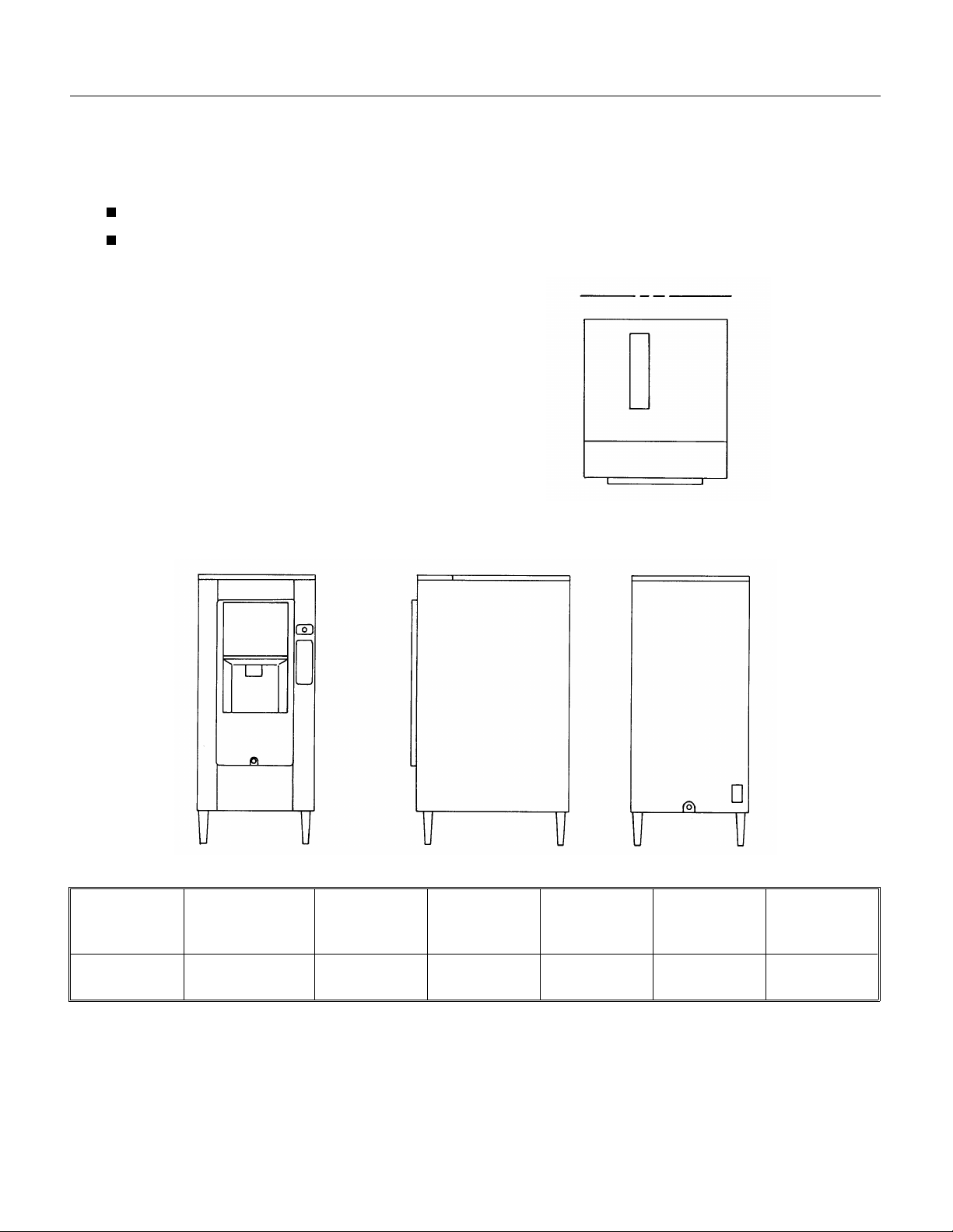
Top View of SLD150
All kits are field inst alle d.
Model Dimension s
(with legs) W
x D x H
SLD150S-1B 22" x 32" x 50" 115/60/1 Stainless
Basic
Electrical
Finish Ice Storage
Steel
Max Fuse
Capacity
90 lb. 15 2.9
Size
Min Circuit
Ampacity
October 1996
Page 2
Page 3
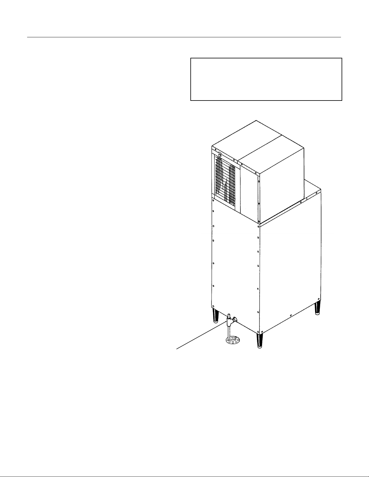
Installation: General
After the carton has been removed from the
dispenser, the legs may be installed.
Place flat portio ns of the carton on the floor beh ind
the dispenser and lay the dispen ser down on its
back.
Thread the legs into the base of the dispenser. Be
sure that the leg s are scre wed in all the way. Tu rn
the leg levelers in all the way.
Move the dispense r to an upright positio n and set
it in the location where it will be ins talled . Not e
where drain lines and elect rical conn ection s will be
made.
Drain:
The dispenser has a 3/4" FPT drain fitting at the
bottom cent er of the back pane l. Con nect 3/4" rigid
tubing to this connection, a vent is recommended
for most installations. Route the drain tu bing to the
building drain. Follow all applicable plumbin g
codes.
SLD150
Note
Remove any packing material from inside the
storage bin. Retain keys for later use.
Check that gasket tape is on the top outside edge of
the dispense r where the ice machine will rest.
Because the drain tubing will be very cold,
insulatio n is recommenc ed.
Electrical:
There is an electrical jun ction box on the lower
back panel
Make the electrical connectio ns there. Follow all
applicable electrica l codes. Use a licensed
electri c ian.
The dispenser must be insta lled so th at it is a
separate piece of equipment from the ice machine.
The drains and ele ctrica l supply mus t be separat e.
Drain
October 1996
Page 3
Page 4
SLD150
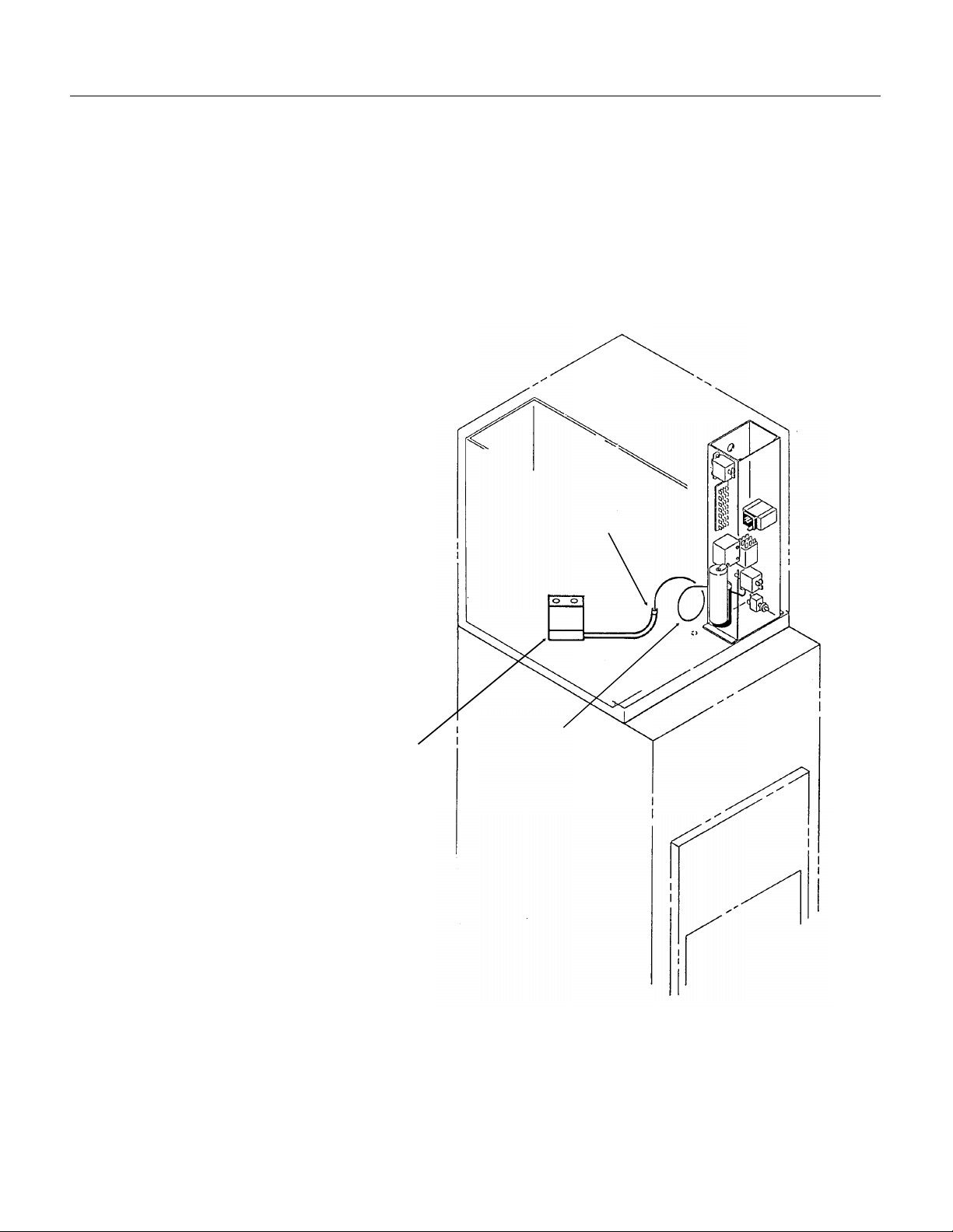
Installati on: Ic e Machine
Check that gas ket tape ha s be en place d at the
outside edge of the dispenser top.
Place corne r post s from th e cart on on top of the
dispenser, at the left and right front corners.
Locate bin thermos ta t brac ket ent ran ce hole, it s
found at the right side of the hole in the top of the
dispenser. Make sure the hole is open.
Place the ice machine onto the dispenser. The ice
machine is heavy, use of a mechanical hoist is
recommended.
The ice machine should be tilted up
slightly. Uncoil about 18" of bin
thermostat capilla ry tube.
Push the end of the capillary tube
thru the plastic tube loca te d to the
left of the compressor.
Observe the tube as it pushes
down o ut of the base. Adjust the
position of the ice machine so that
the capillary tube enters the hole
for the dispenser’s bin thermostat
bracket.
Plastic Tube
Carefully remove cardboard
supports and allow ice machine to
rest on dispenser gasket.
Caution: Bin th ermo stat ca pilla ry
tube must not be kinked or broken
during installation.
Follow all instruct ions fo r
installat ion of the ice mac hin e.
Bin
Thermostat
Bracket In
SLD150
Capillary
Tube
Installatio n of Bin Thermostat
October 1996
Page 4
Page 5

Kits: Coin Mechanism (KSLDC2)
SLD150
A kit is availab le to inst all a coin mech anism, an d
another kit is available to install a room key
mechanism. Bot h come with detaile d inst ruct ion s,
summarized here:
Coin Mechanism, ins ta ll after ice mach ine has
been operating:
1. Disconnect electrical power.
Electrical Shock Hazard.
Disconnect electrical
power before beginning
procedures.
2. Locate key, unlock and remove sink. The n
remove the top front brace and control bo x cover.
4. Remove all the wires from the push butto n
switch.
5. Remove the nuts that secure the push button
cover to the dispenser and remove the cover.
6. Remove the screws that hold the push butt on
switch to the dispenser and remove the push
button switch.
7. Install the small cover plat e from the kit.
8. Remove cover plate on right side of front panel,
below push button switch; use 5/16" nut driver.
9. Install the mountin g pla te fron the kit using the
nuts from the kit.
10. Secu re the coin mechani s m to th e mounting
plate from the inside of the dispenser. Use the
screws, flat was hers and lockwashe rs from the kit.
mechanism and hold in the safe ty int erlo ck switc h.
Push the slide in and release it. The dispen ser
should dispense ice into the container.
17. Check if the pro per amo un t of ice was
dispensed.
If more ice is needed:
••Increase the time by tu rnin g the time r
adjustment dial clockwise.
If less ice is needed:
••Decrease the time by turning the timer
adjustment dial counter clockwise.
The initial set tin g sh ould be 4 on the dial, or 8
seconds . Each se gment equals 2 secon ds .
Important : Disco nne ct the powe r sup ply when
adjusting the timer.
18. Place new sch ematic over the old one.
19. Install th e coin box .
19. Reconnect power to dispe ns er.
20. Repla c e con t ro l box cover.
21. Replace sink .
22. Check operation of coin box and key lo ck. After
everythin g is ope rat ing , give key to use r.
Control Box Layout
Control Relay
Adjustment
Coin Mech
Timer
Coin Mech
Relay
1 1 . Remo ve the cover from th e contro l box.
12. Remove the timer mechanism from the kit and
install it in the control box.
13. Remove wires numbered 8 and 9 from the
control box , they will be rep lace d by new wires
from the kit marked 8 and 9.
14. Install the new wires, followin g the wiring
diagram from the kit.
15. Reconnect th e ele ct ric al po wer supply to the
machine.
16. Place a cont ain er in th e drop zone of the
dispenser. Place a quarter in the slide of the coin
October 1996
Agitation Timer
Electrical Sequence
1. Coin switch closes, connecting power to timer .
2. Tim e r clo se s internal contact s, co nn ec ting
power to gearmotor (and door sole no id if -1B )
3. Gearmotor rotate s dispen se wheel until int ern al
timer contacts (AND cam swit ch cont acts if -1)
open. The time of rota tio n (an d amoun t of ice
dispensed) is determin ed by the timer.
Page 5
Page 6

SLD150
Key Kit Installation: (KSLDK2 )
1. Disconnect electrical power
Electrical Shock Hazard.
Disconnect electrical
power before beginning
procedures.
2. Remove sink and drain pan.
3. Remove cover.
4. Remove control box cover
5. From kit, locate brass fittin g. Obt ain typic al door
lock cylinder from the mot el/ hote l.
6. Insert cylinder into brass fitting (most cylinders
will fit). Mark place where cylinder sticks out past
brass fittin g. Cut off excess cylin de r.
7. Insert cylinde r into hole on plate in kit. Pla ce
switch mounting bracket behind cover plate and
over fitting, with the switch bel ow the fitting. Using
the locknut pro vide d, fas ten th e fittin g in pla ce with
the flats vertica l.
8. Place the cylinder in the brass fit tin g, and
secure to the fittin g with the set scre w.
9. Push hotel/mote l key int o the cylinde r and
adjust lever of micro switch so the switch clo ses
when the key is pushed all the way in.
10. Install plate and switch asse mbly int o
dispenser. Secure with nuts removed from origin al
plate.
1 1 . Remo ve wire #8 from normally open termina l
of the dispenser switch and reconnect it to the
normally open terminal of the room key
microswitch.
12. Disconnect wire #9 from the normally open
terminal of the dispense switch and connec t it to
the normally open terminal of the room key switch.
13. Use wire #6 from kit, and connect the normally
open post of the dispense switch and common of
the room key switch
Install control box cover.
Replace drain pan and sink.
Reconnect po wer and check ve nd ing . Pushing key
in and holding vend but ton do wn should start vend.
October 1996
Page 6
Page 7

Final Check List /Init ial Start Up
1. Check that ele ctrical power has been sup plie d.
2. Check that a drain, separate from the ice
machine, insula te d and mad e of rigid tu bin g, has
been connected to the dispenser.
3. Check that th e ice machin e has be en proper ly
installed per the ice mach ine s inst alla tion
directions .
4. Check that the ice machine/dispenser assembly
is level front to back and left to rig ht.
5. Check that optional kits, if any, have been
correctly installed.
6. Check that the sink ke y, and coin box key if
used, are av aila ble.
To Start:
1. Connect electrical power.
2. Go thru ice machin e sta rt up proce dure s. Let ice
machine make two harves ts.
SLD150
3. Push vend switch button in.
4. Rotor should rotate 1/4 turn and stop.
5. Ice will b e dispensed from ice chute.
6. Remove sink , and che ck dra in area for leaks. If
none, replace sink.
7. Fill out the warranty registration form and place
it in the mail.
8. Give th e operator the key(s) and instructions on
the operatio n and main te na nce of the pro duct.
Check that the operat or kno ws who to call fo r
service, and has the product/service manuals for
the machines.
Electrical Sequence
Pushing the vend button closes a contact to the
gear motor (and to the ice door sole no id of
SLD150-1B mod els).
SLD150-1 model: When the gearmotor begin s to
turn, the cam switch on the gearmo tor clo ses , so
that the vend switch may be released without
interruptin g th e vend ing , until th e cam has move d
1/4 turn. The cam switch then opens to terminate
the ve nd.
SLD150-1 B mod el: The gearmo to r and ice door
solenoid will have power and the dispenser will
continue to operate as long as the dispe nse switch
is pushed in. This mod el als o has a agita tio n cy cle
of 3 seconds every 2 hours. The solenoid does not
engage during agita tio n and no ice is dispe ns ed.
October 1996
Page 7
Page 8

Gear Mo tor
SLD150
Operational Schemat ic
Ice Machine
Bin Thermostat
Storage Bin
Drain
Ice Chute
Sink
Drain Pan
Condensate Pan
October 1996
Page 8
Page 9

Cleaning
SLD150
General Care and Cleanin g
Periodically ins pect and clean the ice dispenser to
keep it operating a t peak performanc e.
Wash the outside of the dispenser with warm
water and soap. Rinse off an d wipe dry.
Cleaning and Saniti zin g of the Ice Storage Bin:
The minerals, chlorin e and other impuritie s in the
water are rejecte d fro m the wate r during the freez e
cycle of the ice machine. These mine rals will
collect in the storage bin. The ice storage bin
should be cleaned and san itize d every 90 days.
1. Remove all of the ice stored ins ide the
dispenser bin and shut off the ice maker.
2. Disconnect electrical power
Electrical Shock Hazard.
Disconnect electrical
power before beginning
procedures.
Wash the entire bin area and the delivery area.
Use a clean brush or cloth.
9. Rinse all areas wash ed with clean, fresh water.
10. Using the ice machin e clea nin g so lut ion , clea n
the ice grill, sink, and water pan. Rinse these
parts with cle an, fresh water.
11. To sanitize: Use a lo cally ap pro ved sa nit izer. A
possible sanit izer: Mix a solut ion of ice machin e
sanitizer and wat er: 1 ounc e of hou sehold blea ch
to 2 gallons of (95
interior surf ac es and the wheel with the sanitize r
solution . Use a cle an cloth .
Scotsman Ice Machine
Cleaner contains acids.
These compounds may
cause burns.
If swallowed, DO NOT
induce vomiting. Give
large amounts of water or
milk. Call Physician
immediately. In case of
external contact, flush
with water.
KEEP OUT OF THE
REACH OF CHILDREN.
o
F.-1150F.) water. Wash all
Moving parts in bin will
cause injury if hands
are in the way.
Disconnect electrical
power before beginning
procedures.
3. Locate key and remove sink.
4. Remove top fron t pane l (in front of ice machin e).
5. Remove the fron t top pane l (abo ve ice chute).
6. Reach int o the op en ing , loca te the large nut
securing the whe el to the driv e shaft . Remo ve the
nut.
7. Pull the wheel of f th e drive shaf t and lea ve it in
the dispenser.
8. Mix a solution of 5 ounc es of ice mach ine
cleaner to 1 gallon of warm (95
o
F.-1150F.) water.
12. Allow the parts t o air dr y.
13. Reassemble wheel and large nut onto drive
shaft.
14. Replace all pane ls.
15. Reconne ct po wer, be sure ice machine is
switched back on.
October 1996
Page 9
Page 10

SLD150
Service Diagnosis
PROBLEM POSSIBLE CAUSE PROBABLE FIX
Does not vend No ice Check ice mac hine
No power Check powe r su pp l y
Vend switch open Check/rep lac e vend swit ch
Sink interloc k switch open Check/rep lac e sink interlo ck
switch
Ice jams in chute Machine is not leve l
Front panel not on all the way Reinstall pane l
Gearmotor open Check/rep lac e gearmotor
Cam switch open (SLD150-1) Check/rep lac e cam swit ch
Adjust cam switch to clos e when
on high part of cam
Ice door does no t op en
(SLD150-1B )
Drive shaft broken Check/rep lac e drive shaft.
Coin Mechanis m Does not vend, no ice Check the above, plus coin switch
Leaks water Bin drain leaks Check bin drain connections and
Check for power to solenoid.
Check linkage from solenoid to
door
Check wiring
Check timer
fittings
Check for clogged bin drain tubing
October 1996
Page 10
Page 11

Removal and Replacement
Electrical Shock Hazard.
Disconnect electrical
power before beginning
procedures.
Gear Motor
1. Disconnect electrical power
2. Locate key and remove sink.
3. Disconnect wires at gearmotor
4. Mark position of cam switch brack et, and
remove bracke t with cam switch from gearmot or.
5. Remove 4 nuts securin g gearmot or base o
cabinet.
6. Pull gearmoto r down and out of cabinet.
7. Remove gearmotor from ba se.
Reverse to reassemble.
SLD150
Drive Shaft
1. Remove all of the ice stored ins ide the
dispenser bin and shut off the ice maker.
2. Disconnect electrical power
3. Locate key and remove sink.
4. Remove top fron t pane l (in front of ice machin e).
5. Remove the fron t top pane l (abo ve ice chute).
6. Reach int o the op en ing , loca te the large nut
securing the whe el to the driv e shaft . Remo ve the
nut.
7. Disconnect wires at gearmotor.
8. Mark po sition of cam switch bracket and remove
bracket with cam switch from ge armot or.
9. Remove 4 nuts securin g gearmotor to cabinet .
10. Pull ge armotor down and out of cabinet.
1 1 . Remo ve six cap screws holding drive shaft
housing to cabinet.
12. Pull drive shaft housin g fro m the bin.
13. Remove snap ring from end of drive shaft, and
tap shaft out of bearings with plastic headed or
dead blow hammer.
14. Reverse to reas semb le.
Dispense Wheel
1. Remove all of the ice stored ins ide the
dispenser bin and shut off the ice maker.
2. Disconnect electrical power.
3. Remove ice machin e from dis pense r.
4. Remove large disp enser to p panel.
5. Reach int o the op en ing , loca te the large nut
securing the whe el to the driv e shaft . Remo ve the
nut.
6. Pull the wheel of f th e drive shaf t and remo ve it
from the dispenser.
Reverse to reassemble.
October 1996
Page 11
 Loading...